All Activity
- Past hour
-
 chunty2026 joined the community
 - Today
-

VedaCAD - Technical Support, Updates & Community VCIDs
VicoWang replied to VicoWang's topic in AutoLISP, Visual LISP & DCL
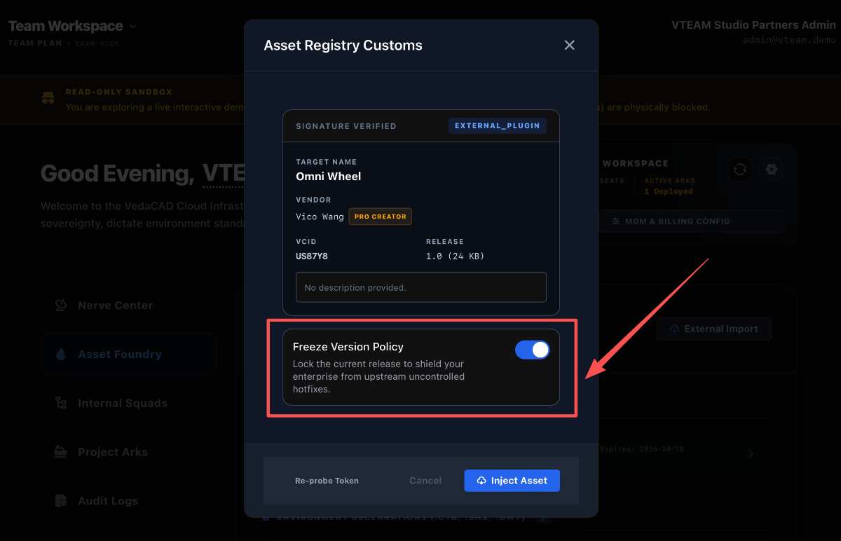
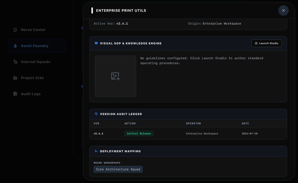
Hi Jeffery, Thanks for the great questions. You have an incredibly sharp eye for deployment architecture, and your questions highlight the exact technical nuances we had to navigate when building our engine. Here is exactly how VedaCAD handles those scenarios under the hood: 1. The Support Path Nightmare (Environment Isolation) We hate path-pollution as much as you do. VedaCAD operates a "Version-Isolated Sandbox" (stored safely in %APPDATA%\VedaCAD\...). When VedaCAD injects enterprise standards (like .CTB or .SHX folders) into AutoCAD's native SupportPath, our LISP microkernel runs a non-destructive prepend algorithm. It parses the existing string, removes only the old VedaCAD sandbox paths, injects the new ones, and leaves every other native or third-party path completely untouched. Your existing CAD setup remains structurally pure. 2. Versioning and Pinning (The Update Strategy) We handle version control via two distinct architectural pathways depending on asset ownership: External Assets (Community VCIDs): Because you don't own the source asset, you cannot mathematically "rollback" the original developer's release. Instead, VedaCAD uses a Freeze Version Policy (Pinning). When an Admin imports an external tool via its ShareCode, they lock it to a specific safe version (e.g., v1.2). If the original developer pushes a buggy v2.0, your enterprise fleet ignores it. Your dashboard simply flags an 'Upstream Patch Detected', giving the Admin the choice to test it first in a sandbox squad, and click 'Deploy Patch' when ready. Internal Assets (Owned by your Enterprise): For plugins your company develops, every single deployment is permanently recorded in a strict "Version Audit Ledger". If a bad script goes live, the Admin simply pushes the corrected version centrally. During their next heartbeat, all CAD terminals will silently hot-swap to the fix in the background. 3. Enterprise Enforcement vs. Personal Customizations This is the most critical balance to strike, and it’s exactly why we split our B2B offering into two distinct operational paradigms: Team Workspace (Hybrid Mode): This is for agile firms. Admins push standard corporate assets, but employees retain their personal CAD autonomy. Their local VedaCAD client still has the 'Manage' card, allowing them to add their own purely local scripts or mount shared VCIDs from the community. However, when a remote kill-switch is triggered by the Admin, our physical shredder will clear all cloud-synced assets (including those community VCIDs), explicitly bypassing and preserving only their pure local scripts. Enterprise Workspace (Zero-Trust Hegemony): This is for strict, defense-level compliance. In the Enterprise tier, user customization is mathematically eradicated. Local installation and external VCID fetching capabilities are completely disabled at the kernel level, and the 'Manage' card physically disappears from the user's interface. They can only see and execute what the Enterprise Foundry explicitly assigns to their Squad. If you’d like to test the sandboxing logic yourself, feel free to sign up for a personal account to try the client. You can also explore the exact enterprise management dashboard we discussed by clicking the 'Get Demo' button on the Team or Enterprise cards on our pricing page (vedacad.com/pricing). I'll keep the release notes updated in the main post. I'd love to hear your thoughts once you've put it through its paces! Cheers, Vico
-

VedaCAD - Technical Support, Updates & Community VCIDs
Jeffery2145 replied to VicoWang's topic in AutoLISP, Visual LISP & DCL
Being able to isolate the local environment sounds useful because one of the recurring headaches with CAD plugins is that a perfectly working setup can break after another application or plugin changes a support file or load path. For the cloud side, I'd also be interested in seeing a little more detail about versioning and rollback. If a developer publishes an updated package and it introduces a problem, can users or project admins pin a specific version, or quickly revert to the previous one? Likewise, for the Enterprise tiers, the RBAC and Project Ark approach sounds useful for subcontractor workflows. The practical test for me would be whether an admin can enforce a known plugin/environment configuration without preventing individual users from keeping their own unrelated CAD customizations. I'll definitely keep an eye on the release notes. Having the changes documented in one thread should make it much easier to tell whether a problem is specific to a new VedaCAD version or to the underlying CAD setup. -
[LISP plugin] Omni Wheel-a custom radial menu tool
VicoWang replied to VicoWang's topic in AutoLISP, Visual LISP & DCL
Hi Ajmal, First of all, thank you so much for this incredibly detailed and insightful reply! It is a rare pleasure to connect with a fellow developer who has navigated the exact same UX/UI challenges for marking menus. Your hard-earned lessons from the Revit side are absolute gold. As you suggested, I have attached a short video/screen recording to this post so you can finally see it in action! I read through all your points, and it is fascinating to see where our approaches align and where our design philosophies (and platform constraints) diverge. Here are my thoughts on them: 1. Aim by pointer angle (Infinite Ray) vs. Bounded Shape Your approach: Trigger by angle, ignoring the outer boundary. My approach: Angle-based, but bounded by a maximum outer radius. Verdict: Yours is a fantastic idea for UX. You are totally right—removing the outer boundary gives it that agile, "game wheel" feel. It is a really interesting approach that makes perfect sense for that kind of fluid interaction. 2. Number keys (1-9) for blind operation Your approach: Hitting 1-9 to execute directly. My approach: Purely mouse-driven. The Philosophy: Your idea is excellent if the wheel is the primary input method. However, my wheel is designed as a supplement to VedaCAD. In our ecosystem, the absolute most frequent commands are already mapped to standard keyboard shortcuts (Priority 1). The wheel is designed for "Priority 2" commands—those that are necessary but slightly less frequent. The logic is: if a user is already using their keyboard, they use shortcuts; but if their hand is driving the mouse and they double-click to summon the wheel, I want to keep the interaction 100% mouse-centric. Mixing keyboard triggers into the wheel breaks that flow for our specific use case. 3. Visuals and The Configurator UI Your approach: Flat graphics, silent fallback, and a drag-and-drop visual configurator. My approach: Flat graphics, silent fallback, but a standard list-based dialog UI for settings. The Platform Reality: We completely agree on dropping glow effects for performance and using silent fallbacks. I also agree that your drag-and-drop UI is the ultimate gold standard for user experience! However, one of my strictest design constraints was building this in 100% pure AutoLISP with zero external dependencies, maintaining backward compatibility all the way to AutoCAD 2006. In pure AutoLISP, the native DCL (Dialog Control Language) is extremely primitive and simply cannot handle drag-and-drop. Achieving that would require injecting VBA or .NET/ARX dependencies, which breaks the lightweight, "plug-and-play" nature of this script. So, the list UI is a necessary compromise for pure LISP architecture. 4. Grey out/Validate commands in one pass Your approach: Evaluate everything once before the wheel opens; validate if CAD accepts it. My approach: I currently use a brute-force CAD trick—sending a "double-Esc" sequence to cancel any active operations before forcing the new command macro. Verdict: The Revit API environment is much stricter, so your pre-validation makes perfect sense there. However, in my architecture, the wheel acts strictly as a lightweight command trigger mechanism(essentially mimicking keyboard input). It is not deeply bound to the underlying LISP routines of the target commands. Therefore, it doesn't evaluate whether a command is valid for the current selection—and realistically, it doesn't need to. Adding complex state-checking and UI rendering logic (like grey-outs) would just introduce unnecessary overhead to what is meant to be a simple, fast macro launcher. Regarding your two technical curiosities: Since I am drawing native geometry directly into the AutoCAD model space, you are spot on that those two issues were the hardest to crack. Here is how I solved them natively: Zoom Scaling: The wheel does not scale with the drawing; it scales with the screen. When summoned, the script fetches the active viewport's real-time physical screen height. It uses this to dynamically calculate the precise mathematical radii for the rings. So, whether you are zoomed into a tiny screw or zoomed out to a city plan, the math draws the wheel at the exact same physical size on your monitor. The Double-Click Conflict: You are right that double-clicking native CAD objects opens the block/text editor. To dodge this, my double-click event listener performs a native "hit test" exactly at the cursor's location. If it detects any existing drawing entity under the pointer, the script instantly aborts and lets the native CAD double-click editor take over. The wheel only deploys if the hit test confirms the cursor is over 100% empty space Again, thank you for sharing your architecture. I would absolutely love to see how your Revit marking menu looks and feels! If you have a GIF or video lying around, please do share it here.
-

[LISP plugin] Omni Wheel-a custom radial menu tool
BIGAL replied to VicoWang's topic in AutoLISP, Visual LISP & DCL
@Ajmal "Once you know your own layout you stop looking at the wheel at all," It's called a Digitiser, a proficient user would not look at the digitiser but knew where commands were. Yes have to be old like me. I have a "Medion pad" that works as a digitiser. Played with it but went back to a mouse. - Yesterday
-
 belltlson984 joined the community
 -
 VincentP13 joined the community
 -

[LISP plugin] Omni Wheel-a custom radial menu tool
Ajmal replied to VicoWang's topic in AutoLISP, Visual LISP & DCL
Nice work. I built the same kind of wheel for Revit a while back, so it was good to see someone doing it on the AutoCAD side. I could not see it running from the thread either, so a short screen recording would probably get you more replies here than anything else. Everything below is from my side, on Revit, so translate it however it fits. These are the ones that cost me the most time. Aim by the pointer angle, not by which shape is under the pointer. Point in a direction and that wedge lights up, whether you are near the middle or way out past the rim. That one change is what made mine feel like a game wheel instead of a menu. Number keys 1 to 9 pick a slot directly. Once you know your own layout you stop looking at the wheel at all, and that is where the real speed comes from. Grey out a slot that cannot run right now, and work all of them out in one pass before the wheel opens. Mine has to check the current selection to answer that. Doing it slot by slot meant a 50,000 element selection got walked once for every slot on the wheel. Once for the whole wheel fixed it. Check the command will really be accepted before you fire it. When mine was refused, nothing ran but the wheel still closed as if it had worked. That is the worst kind of failure because it looks like an answer. Smaller things I would not have guessed: Test the wedge maths outside CAD. I rebuilt mine as a standalone renderer and produced every slot count at every wheel size as images. Far quicker than restarting the host for each attempt, and it found a label collision at my highest slot count that I would never have caught by eye. Store the command name in the slot, not the button text. Rename a button later and the layout survives. Slot 1 at the top, the rest clockwise, always. The muscle memory is the whole point, so that order can never move. Drop any glow or fade. Mine had a soft shadow on the hovered wedge and a fade across the whole ring, and both were being recomputed every time the pointer crossed a boundary. A brighter fill and a thicker outline read exactly the same and cost nothing. Only redraw the wedge that changed, never the whole ring. Let the config file be missing or corrupt without complaining. Mine falls back to the defaults instead of throwing a message at me, and I have never once wanted the message. Do not let dead keys close it. Enter, space and a number higher than my slot count all used to dismiss the wheel doing nothing, which just felt broken. Open the settings from the wheel itself, and let people set it up by dragging onto a real wheel instead of filling in a list. Drag a tool onto a slot to fill it, drag one slot onto another to swap them. Mine draws the same ring at a smaller size for that, so what you arrange is what opens. Two things I am curious about, since you draw with real entities in model space rather than a window over the top. Does the wheel stay the same size on screen at any zoom, or does it scale with the drawing? Mine sits in a window above everything so I never had to deal with that, but it looks like the harder half of your approach. And the double click. In AutoCAD a double click on an object opens its editor, so what happens when the pointer is over an entity instead of empty space? I went with a keyboard shortcut and dodged the question, but yours is the nicer gesture if it works. -
[LISP plugin] Omni Wheel-a custom radial menu tool
VicoWang replied to VicoWang's topic in AutoLISP, Visual LISP & DCL
It's cool how we both use LISP to bypass tedious UI coding! What you described about unzipping CUIX to tweak the XML is very much like tweaking static DCL. It's a great, geeky hack for customization, and highly reliable since the underlying files are persistent. Though we take slightly different paths on file management. Instead of juggling multiple external files to get a feature working, I'm totally obsessed with the 'all-in-one LISP' paradigm. In my VedaCAD main program(Fully utilized temporary DCL technology to achieve multi-level dynamic DCL pages similar to web pages), the Gomoku game, and this OW LISP, I generate temporary DCLs on-the-fly. I basically use native CAD entities to draw the interface directly in model space, and then destroy/clean up everything right after the routine finishes. Pure plug-and-play. - Last week
-
[LISP plugin] Omni Wheel-a custom radial menu tool
BIGAL replied to VicoWang's topic in AutoLISP, Visual LISP & DCL
Gif is there now, a cool idea. The menu issue for me is writing a CUI or CUIX for a custom ribbon, but say using notepad or excel, if you change a cuix to zip can look inside. It is made of a few XML files, that would be helpfull. I also made a write mnu lsp so it helps the typing time, use it for pop menu's. One of the things I have played with is make dcl code from a dwg, uses blocks etc, but need to make it look at a more complex dcl. -
@Steven P It could be as simple as supporting mtext in a dcl. Then color and style would work.
-

Why does the same CAD drawing behave differently on two computers?
Steven P replied to indiancad's topic in AutoCAD 2D Drafting, Object Properties & Interface
If it is going to a client I'll try to keep it all basic - no add ins, standard fonts, etc, if I can, on the assumption that their doc control will copy just the dwg file and all the rest will be lost to them at worst and at best when it is sent out again whoever sends it won't e-transmit, just the dwg, so we have to go round and round to get the rest. -
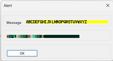
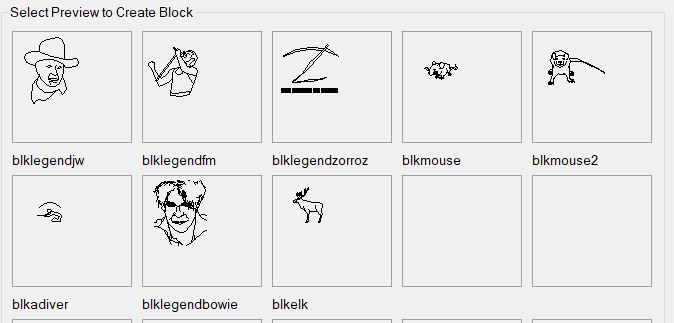
All image tiles.. nothing too fancy.. the time was spent creating each letter as an image Letter Coordinates.lsp
-
[LISP plugin] Omni Wheel-a custom radial menu tool
VicoWang replied to VicoWang's topic in AutoLISP, Visual LISP & DCL
A bit strange, I can see the GIF here.
-
[LISP plugin] Omni Wheel-a custom radial menu tool
BIGAL replied to VicoWang's topic in AutoLISP, Visual LISP & DCL
No Gif. Use window+shift+r thats windows built in recorder. -
Why does the same CAD drawing behave differently on two computers?
BIGAL replied to indiancad's topic in AutoCAD 2D Drafting, Object Properties & Interface
If you use Etransmit it will add extra files to what is exported, in particular say custom fonts and xrefs. -
[LISP plugin] Omni Wheel-a custom radial menu tool
VicoWang replied to VicoWang's topic in AutoLISP, Visual LISP & DCL
I tried to fix the demo file, can you see that GIF? This plugin does not provide the source code. -
@SLW210, yes well aware of using VBA forms rather than DCl a much better way for input dialogs, running VBA is pretty easy load the dvb then run the sub function. The only thing is must have the VBA runtime installed, which is a separate install in Acad. It is interesting though that a few years ago now Autodesk announced they would be discontinuing support for VBA but it is still there, I think the powers to be thought every one would jump onto .NET. @Steven P can you post code would like to try in Bricscad. The idea was based on a forum request to see your different text styles in a dcl.
-
[LISP plugin] Omni Wheel-a custom radial menu tool
Steven P replied to VicoWang's topic in AutoLISP, Visual LISP & DCL
Could you put up a screen shot so we know what you want us to download - i'm very sceptical about just down loading unknown files. Better again would be the code to look at first of course. -
[LISP plugin] Omni Wheel-a custom radial menu tool
VicoWang posted a topic in AutoLISP, Visual LISP & DCL
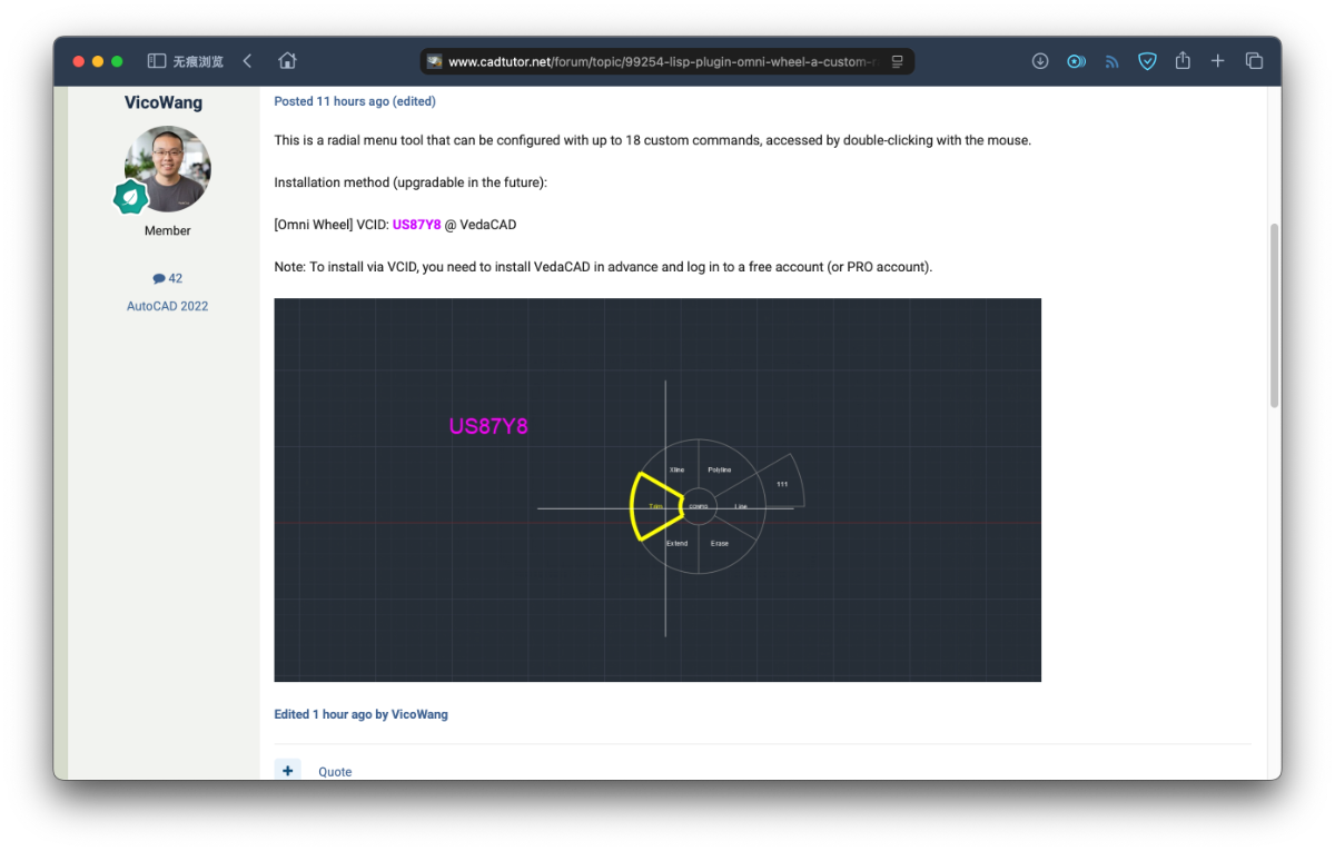
This is a radial menu tool that can be configured with up to 18 custom commands, accessed by double-clicking with the mouse. Installation method (upgradable in the future): [Omni Wheel] VCID: US87Y8 @ VedaCAD Note: To install via VCID, you need to install VedaCAD in advance and log in to a free account (or PRO account).
-
Don't know about that.... ...not easy but because it was a quiet Christmas week last time... and if we can insert image buttons, we can insert custom button shapes: (just realised I have shamelessly not credited RLX? with the mouse) Suspect the same as SWL though, I'd be surprised if anything changes. BricsCAD is likely to maintain compatibility with AutoCAD and not go too far away... so 'BricsCAD' DCLs will work as 'AutoCAD' DCLs Colours and fonts would be handy... which is why I made up the first one, though Bold and Italic might be a better first step, and multiline text (I have a few with filepaths displayed where word wrapping would save me a few lines of coding). Not sure what else, but I am sure to think of something over the net week or so to add
-
 mostar joined the community
 -
You can handle that by separating the prefix from the numeric part of the ADDRESS attribute and sorting on the components rather than treating the whole value as a plain string. For example, L1-001, L1-002, L1-010 should be compared using L1 as the prefix and 001, 002, 010 as the numeric portion. The same idea works for something like 1/1/1-001, where the part before the final hyphen is the prefix. If the Lisp currently assumes that ADDRESS contains only digits, that's probably the part that needs changing. The important bit is to extract the number after the final -, convert that substring to an integer, and use it as the sort key. That will also preserve the expected order for values such as ...-002, ...-010, ...-100 instead of getting alphabetical ordering. If different prefixes need to be grouped together, I'd make the sort key something like (prefix, numeric part). That should let the same routine handle all three formats without having to hard-code L1 or 1/1/1.
-
Jeffery2145 joined the community
-
.thumb.jpg.615654602253be56b2fbd5d064834780.jpg)
Why does the same CAD drawing behave differently on two computers?
indiancad posted a topic in AutoCAD 2D Drafting, Object Properties & Interface
Both systems may have the same drawing, but the result can still be different. Fonts, SHX files, plot styles, support paths, and installed add-ons can change how the drawing behaves. This is why sending only the DWG file is sometimes not enough. For team projects, I usually keep the required support files together with the drawing. It makes troubleshooting much easier when another user opens the same file. What additional files do you always send with a DWG? -
You could always use VBA, and/ or .NET to make the User Forms and work the LISP. I have a VBA or 2 around that I did, one runs Scripts in AutoCAD, I'll have to see what the others may do as I really haven't used them in a while. The inbuilt one works for me for now, but always could use more options. Autodesk hasn't made meaningful improvements to LISP since 1999 for AutoCAD 2000 and as you stated 0 DCL in 40 years, so don't get your hopes up on BricsCAD picking up the torch. Worth a try I would imagine.
-

Why does Object Snap sometimes stop working correctly in CAD?
SLW210 replied to indiancad's topic in AutoCAD 2D Drafting, Object Properties & Interface
Shift + Right-Click brings up a menu, except for Geometric Center, they all have a 1 letter shortcut, once in the habit it is very fast to select the snap you need. -

Free Multi Plot Lisp – Fast Batch Printing for AutoCAD, BricsCAD & ZWCAD | Model/Layout, Zone Plotting & PDF Merge
CamDuy replied to CamDuy's topic in AutoLISP, Visual LISP & DCL
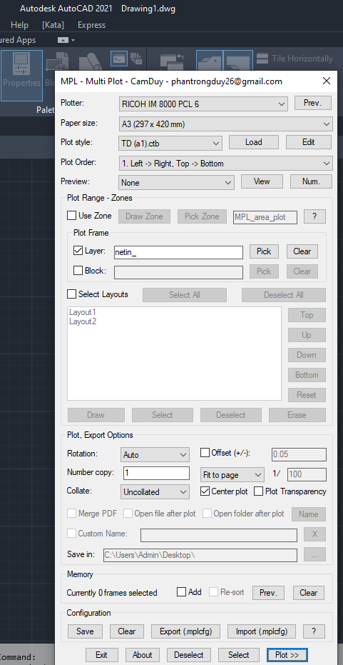
I am still using it with AutoCAD 2021.
-

AutoCAD 2027.1 Now Available: Smarter Autodesk AI Assistance and Smoother Collaboration
animal1103 replied to The AutoCAD Blog's topic in AutoCAD Blogs
-

Free Multi Plot Lisp – Fast Batch Printing for AutoCAD, BricsCAD & ZWCAD | Model/Layout, Zone Plotting & PDF Merge
Nikon replied to CamDuy's topic in AutoLISP, Visual LISP & DCL
The code doesn’t work (Autocad 2021 localized ) command: MPL Unknown command "MPL"