All Activity
- Today
-
 furqanibrahim joined the community
 -

CREATE PERPENDICULAR DIMENSION BETWEEN TWO PARALLEL POLYLINES
devitg replied to SCHNIPPLES's topic in AutoLISP, Visual LISP & DCL
@SCHNIPPLES please upload your-sample.dwg -
 ryo83 joined the community
 -

Reduce file size.
SLW210 replied to Bandido's topic in AutoCAD 2D Drafting, Object Properties & Interface
Best way to clean a difficult file is WBlock, not sure what had those bloated like that. -
AutoCAD for Mac 2022 – Lineweights change thickness when zooming (display bug)
SLW210 replied to gkathan's topic in AutoCAD Bugs, Error Messages & Quirks
What are the computer specifications? What OS? Lines, LWPolylines, 2DPolylines or 3D Polylines I doubt there is a permanent fix except to repair the drawings that have the issue, though it could still be an issue with your computer graphics. If it's polylines, try exploding them to lines, then PEDIT them back to LWPolylines, also try an Audit on the affected drawings. You could post an example drawing that has the issue, maybe it will show on other's computers if it's a .dwg issue.- 1 reply
-
- 1
-

-
 Henk594 joined the community
 -
Batch DWG to PDF plot LISP File
SLW210 replied to Chicane_Apex's topic in AutoLISP, Visual LISP & DCL
The OP is using AutoCAD LT 2026 and cannot use a .NET AFAIK. You are new so I removed your link to YouTube. -
 lehoang6198 joined the community
 -
Batch DWG to PDF plot LISP File
lehoang6198 replied to Chicane_Apex's topic in AutoLISP, Visual LISP & DCL
Experience my plugin written with .NET API. -
 COOKIE2000 joined the community
 -
 AD_743 joined the community
 -
If you want to load lisp as it is, then you shouldn't localize that first (defun) along with other variables... Only if you push it (that first defun) in main body of command function (defun c:) you should localize it, wich is what I suggested... As you observed CAD won't recognize localized defun if it's out of main command function and bahave like global variable, though as if you had globals they should never be localized as they also won't be recognized...
-

VS Code AutoCAD Lisp Snippets
BIGAL replied to CivilTechSource's topic in AutoLISP, Visual LISP & DCL
@CivilTechSource Like you, It is a good idea to have a library of functions that you use all the time, in my Excel lisp there are 41 defuns so just copy and paste the ones I want to use, same with my Multi lisps for dcl's. often set them to write a dcl and then convert that file to dcl lisp code, like 3 lines of code to make a dcl. I have a VLAX lsp open all the time in my Notepad++ so again copy paste a function. I have a lot of lisp's saved as a function name eg Sort.lsp has various sort methods in it. I use windows "Findstr" a lot in a bat file so can look through an entire lisp directory for a keyword, identifies lisp files with that key word and copy and paste what I want out of existing code. You can in a lisp load an entire other lisp program and continue and use functions in that new lisp, I mention it as you could have little tiny lisp's like your "make layer.lsp" and just load when required. eg (if (not ah:butts)(load "Multi radio Buttons.lsp")) so you could have a few load lisp's at start of code saving lots of copying and pasting. Interested what others do.
-
LISP for breaking multiple polyline at 'insertion point' of multiple Blocks (AUTOCAD 2026)
BIGAL replied to xenru's topic in AutoLISP, Visual LISP & DCL
For me simplest and quickest is use a wipe out in the block, set to background then will auto obscure line underneath. Hopefully the result you want.
-
@BIGAL Please share me. You can reach me at WhatsApp +60129736757
-
 ae245 joined the community
 -
Hi All, just wanted to thank everyone again for helping me so far in my lisp journey! As a token, I worked on a VS Code extension for AutoCAD snippets. This so it can allow users to type in quickly common functions the use all the time (e.g. search layer if dont exist create layer and so on). So far I have added the comment section. Happy to receive feedback and suggestions. Thank you https://marketplace.visualstudio.com/items?itemName=CivilTechSource.autocad-lisp-snippets
- 1 reply
-
- 1
-
- Yesterday
-
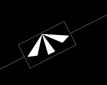
How I draw this type of long break line
BIGAL replied to Joeg's topic in AutoCAD 2D Drafting, Object Properties & Interface
There is no problem in drawing that type of break it just involves a custom lisp to break the lines and draw wiggly lines, the amount of wiggle may have a couple of FUZZY values or scale factors. even a block just scaled to fit. To write your own lisp and its a good task to start learning, Draw a line say 1 unit long vertically one end at 0,0, the turn off snap and draw a wiggly Pline. Use list select pline and copy out the co-ords, to notepad You have 1/2 your code now, just make the points, use a scale factor on the Y value to adjust the points for the 2-3/8 then can draw the pline at correct position. Ok now the easy answer make a block and again draw a line, do the pline, erase the dummy line, save block. you can insert the block and scale it to suit the length required. insert block twice, after breaking line. I would turn second insert upside down so looks a bit more random. Ok I have avoided line work on any other angle than horizontal, on purpose, you can pick a point on 1st line break it, then perp to other line and auto break it also. This involves getting linework details like angle of lines. The actual pline could have randomness added to it so no 2 plines are quite the same by in example vertical, adjusting the x value within a range so 2 breaks don't touch. So have a go make a block and your homework is in lisp, Getpoint pt1, Polar for 2nd point, based on horizontal line, then Break using 2 points, getpoint again Pt2 using perp , break other side. Simple block answer.
-
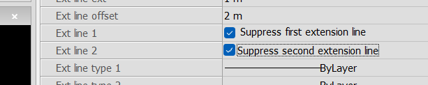
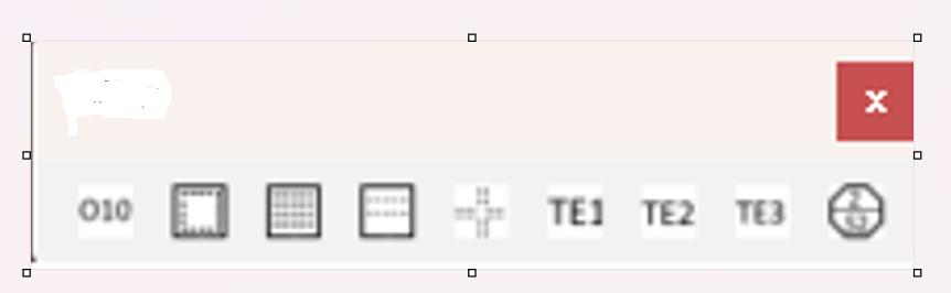
Yes is the answer to a lisp but it will cost you, but you will get much more than just what you have asked for as I have different lisps for Concrete slab design. More than is shown in this toolbar. Two solutions needed, it is not that hard to do a dimension using correct style turn off all the extensions etc and you will have a double arrow dimension, 1st step. Don't really need code. Pick 1st point then use perp for second point and over ride dimension with "A7" etc. Can do a mini defun in lisp if needed. You should be using a dwt "drawing template" for your work so the Dim style would be there already. Second step is a line with donuts at intersection, you use (SSGET "F" pts (list (cons 8 "REOBARLAYER")))) where pts is (list pt1 pt2) you can then draw a dummy line and use the vl Intersectwith method to find the intersecting points and draw donuts. That is your homework plenty of examples about SSGET and Intersectwith.
-
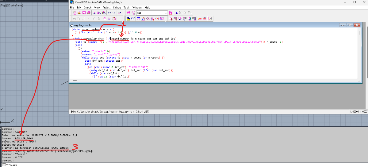
Hi, first of all thanks a lot, i am only beginner in my LISP journey, and for me its hard to find good info in my native lang, so any usefull help is excelent. About UCS it worked fine, lw_orth now creates line in any UCS. (command "_,ucs" "_w") and (command "_.ucs" "_p") worked out! About regular_draw i tried to implement stuff you descriibed in post, but after that console says next: I setted SNAPUNIT to 1.0,1.0 as you said. Could you help me where am i wrong in adjusting regular_draw comand, it seems what i was looking for
-
 gkathan joined the community
 -
With LWT ON, lineweights visually change thickness when zooming in/out. Toggling LWT OFF → ON fixes the display temporarily, but the issue returns on the next zoom. Important: this does NOT happen with all files. Some DWGs display lineweights correctly, while specific files consistently show the issue. The problem appears in both Model and Layout. Plot/PDF output is always correct, so this seems to be a screen redraw / zoom rendering issue, possibly file-related. Tested with no success: LWT/LWDISPLAY, LINESMOOTHING=0, REGEN/REGENALL, Model vs Layout. Please, if anyone has encountered this behavior and found a permanent fix in AutoCAD for Mac 2022 (without resetting preferences or upgrading), I would really appreciate your help.
-

Select all the lines that are vertical
ryanatkins49056 replied to Isaac26a's topic in AutoLISP, Visual LISP & DCL
@Isaac26a One option you may want to consider outside of coding as well is an inbuilt AutoCAD command called QSELECT. You can select what's on the screen. The in the dialog box that appears play with all the filters available. For example select all lines the are equal to 90degrees. -
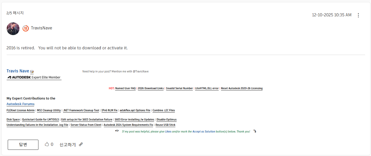
Found this little gem, I guess perpetual license means F - Off, buy our subscription
-
I went through the links thoroughly, thk you for that. Its not allowing me to install
-

Reduce file size.
Bandido replied to Bandido's topic in AutoCAD 2D Drafting, Object Properties & Interface
Many thanks. -

CREATE PERPENDICULAR DIMENSION BETWEEN TWO PARALLEL POLYLINES
SCHNIPPLES posted a topic in AutoLISP, Visual LISP & DCL
Hello CadTutor fam, I am a complete newb at creating Lisps. I am trying to create a lisp that automatically places a dimension between two parallel lines (this is a repetitive task in my field). I've attached the lisp I've got so far, but it only places a line perpendicular to the selected lines. Can someone please help out/point me in the right direction? tpdim.lsp
-
Being as it is an older non-supported version, your options are limited. There was a lot in those 2 links, what did not work?
-
Reduce file size.
SLW210 replied to Bandido's topic in AutoCAD 2D Drafting, Object Properties & Interface
I WBlocked them. new Lines and arcs.dwg new font.dwg -
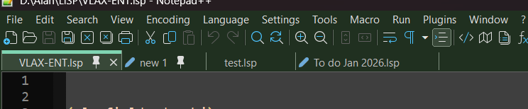
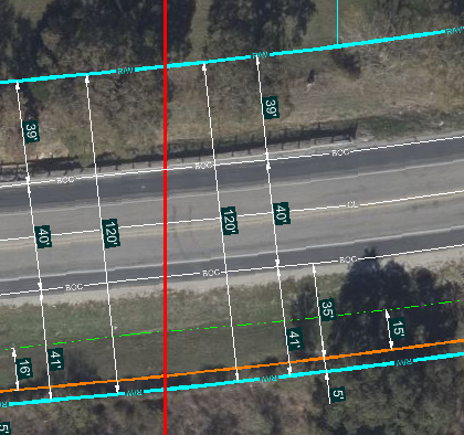
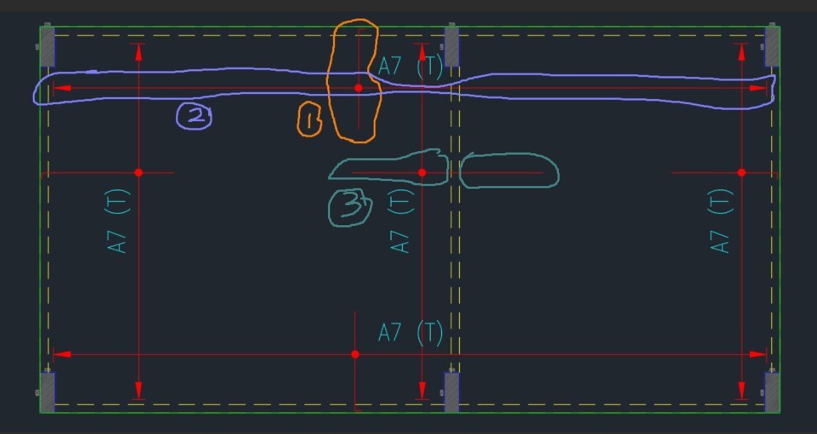
Hi Team, I wish to create a Lisp code for slab rebar detail that has the following conditions, Legend = The perimeter green line represents the edge line of the slab, the yellow dashed line represents the internal beam where the slab is continuous. Clouded with orange colour is the slab rebar. Clouded with purple colour is the arrangement of slab rebar in that direction. Condition 1 = User to point 6 locations to create the slab rebar length. The starting point of the rebar will be the location at last 33.33% or one-thirds length of the 1st and 2nd location. It applied the similar for 3rd and 4th location which to determine the end point for the rebar length, as shown in item 3 in the picture. Subsequently, to point 5th and 6th location to create the length of the rebar arrangement (arrow), as shown in item 2 in the picture. This will allow for creation in both vertical and horizontal directions. To allow the user to point the location without straight alignment. Condition 2 = User to point 6 locations to create the slab rebar length. If the slab rebar is started at the slab edge (green colour line), user to type "x" and point 1st location, this represents the started point of the rebar, as shown in item 2 in the picture. Automatically, 2nd location to be skipped and continues with the 3rd, 4th, 5th, and 6th location. If slab rebar ended at slab edge (green colour line), user to type "x" and point the 3rd location and 4th location to be skipped. - The start and end of the slab reber shall finish with the 90 deg bent with 100mm length. - Create the default text A7 (T) at the centre. - Create solid circle with 100 diameter at the intersection of the line as shown in the picture. - The line layer to follow the layer as per the drawing attached. Kindly advise the lisp code above. Thanks. Drawing1.dwg
-

LISP for breaking multiple polyline at 'insertion point' of multiple Blocks (AUTOCAD 2026)
Saxlle replied to xenru's topic in AutoLISP, Visual LISP & DCL
Something like this!? ; ***************************************************************************************************** ; Functions : PLBRJ ; Description : Breaking POLYLINE at blocks insertation points and joined into the one POLYLINE ; Author : Saxlle ; Date : January 19, 2026 ; ***************************************************************************************************** (prompt "\nTo run a LISP type: PLBRJ") (princ) (defun c:PLBRJ ( / ent joinList ptlist ss len spt ept i breakPoint) (setq ent (car (entsel "\nSelect the POLYLINE:")) joinList (list) ptlist (mapcar 'cdr (vl-remove-if-not '(lambda (x) (= (car x) 10)) (entget ent))) ss (ssget "_F" ptlist (list (cons 0 "INSERT"))) len (sslength ss) spt (vlax-curve-getStartPoint (vlax-ename->vla-object ent)) ept (vlax-curve-getEndPoint (vlax-ename->vla-object ent)) joinList (append (list spt) joinList) i 0 ) (while (< i len) (setq breakPoint (cdr (assoc 10 (entget (ssname ss i))))) (command "_.BREAK" breakPoint "_f" breakPoint breakPoint) (setq joinList (append (list breakPoint) joinList)) (setq i (1+ i)) ) (setq joinList (reverse (append (list ept) joinList)) ss (ssget "_F" joinList (list (cons 0 "LWPOLYLINE"))) ) (command-s "_PEDIT" "m" ss "" "j" "" "") (prompt "\nThe POLYLINE was broken at blocks insert points and joined into the one POLYLINE!") (princ) )
-

How I draw this type of long break line
Joeg posted a topic in AutoCAD 2D Drafting, Object Properties & Interface
How can I draw this kind of break line on autocad. See file attached. Thanks. 20260119_090353.heic -
thks for the reply, that did not work, the 2026 trial version installed without issue. I posted this issue in the autodesk forum, I looked today the moderator removed it