All Activity
- Past hour
-
 KG_G joined the community
 -

Align the extension lines to the short line of each selected size
GLAVCVS replied to Nikon's topic in AutoLISP, Visual LISP & DCL
Do you really need to disassociate the dimension? If you don't need to for another reason, you can delete that part of the code. -
Align the extension lines to the short line of each selected size
GLAVCVS replied to Nikon's topic in AutoLISP, Visual LISP & DCL
(defun c:DimAssOf ( / ss e le n) (vl-load-com) (prompt "\nSelect DIMENSION to disable associativity: ") (setq ss (ssget '((0 . "DIMENSION")))) (if ss (progn (command "_.DIMDISASSOCIATE" ss "") (prompt (strcat "\nDone: associativity is disabled for " (itoa (sslength ss)) " dimensions." ) ) (while (setq e (ssname ss (setq n (if n (1+ n) 0)))) (setq le (entget e)) (entmod (subst (list 14 (cadr (assoc 13 le)) (caddr (assoc 14 (entget e))) 0.0) (assoc 14 le) le)) ) ) ) (princ) ) - Today
-

Solidworks Macros Export Tabel to Excel / Import Tabel from Excel
mhupp posted a topic in .NET, ObjectARX & VBA
Sharing These two VBA macros I made to help with updating tables in Solidworks. As you can use formulas to fill out or update information in excel quickly. They are both called from the Solidworks side. Export from SW to Excel Checks for a Selected table in Solidworks Checks for excel Activeworkbook Checks Activeworkbook name against list of workbooks not to export to Will exit if match Will prompt the user if any data will be overwritten in Activeworkbook Each cell format is changed to text before output so excel doesn't overwrite numbers with leading 0's or other things. Else just outputs to active workbook with Autofit Import to SW from Excel Checks for Excel Activeworkbook Takes Activeworkbook Selection and Imports to a Solid Works drawing on the right side outside of Paper Space. Zoom to fit after import. Have to move the table to import another selection or they will be on top of each other. what is seen excel is whats transferred. (no formulas or calculated values) (cell has a number that has 4 decimal place 10.1234 but is only showing two 10.12) 10.12 is what is sent to Solid Works Export.swp Import.swp -
I can get the marker location using your code, BigAL, but I can't set it. The closest I came up with is this statement: (vlax-put-property obj "Location" (vlax-3d-point <northing> <easting> <elevation>)) but I get error: Automation Error. The parameter is incorrect. I see that a lot doing VLA code. Maybe there's another step to get the right variant format?
-

Align the extension lines to the short line of each selected size
Nikon replied to Nikon's topic in AutoLISP, Visual LISP & DCL
The blue dimension should become the same as the red one. -
vlax-curve-getClosestPointToProjection returns inconsistent results
mhupp replied to IToastThereforeIAm's topic in AutoLISP, Visual LISP & DCL
I Really need to start using grread and grdraw more. seen some really nice things the past few week on here. what happens if you take out LM:rounddown function call? -edit i haven't run the code but might be something in the (if (< dst dse) that isn't updateing the cpt point correctly. that is making "outside" the other line. -
I thought about using MLines, but decided against it because once I offset, I'm generally modifying to draw in curb ramps, etc. I've considered using different layers, but I've never been able to get other people on board. Might be time to give it another attempt. For grading, I have a separate program I wrote that creates my featureline curb offsets based on a selected featureline.
-
Align the extension lines to the short line of each selected size
Nikon replied to Nikon's topic in AutoLISP, Visual LISP & DCL
Sometimes the extension lines of associative dimensions are stretched (for example, to the origin of coordinates ) when inserted into another drawing. Now I've found a way to disable dimensions associativity, but I don't really like it. I only find out that the dimensions have lost their connection with the object when I insert them into another drawing (or turn on the annotation monitor). So I thought it would be possible to align the extension lines to a smaller extension line. Maybe there is a better way... ; disable associativity of only selected dimensions (defun c:DimAssOf ( / ss) (vl-load-com) (prompt "\nSelect DIMENSION to disable associativity: ") (setq ss (ssget '((0 . "DIMENSION")))) (if ss (progn (command "_.DIMDISASSOCIATE" ss "") (prompt (strcat "\nDone: associativity is disabled for " (itoa (sslength ss)) " dimensions." ) ) ) ) (princ) ) extension lines.dwg -
Align the extension lines to the short line of each selected size
mhupp replied to Nikon's topic in AutoLISP, Visual LISP & DCL
I'm guessing they have a drawing and want all the long blue dim extension lines to be shortened to where the dimension is. but the top blue one looks like its pulling from the right and left like the dimension itself is inside the feature its measuring. were the bottom red is only pulling from the right. -
Align the extension lines to the short line of each selected size
GLAVCVS replied to Nikon's topic in AutoLISP, Visual LISP & DCL
I don't think we've understood your question yet (at least I haven't). You might need to elaborate a bit and add some more images. -

Solidworks VBA for renaming components in an assembly
SLW210 replied to dnenad's topic in SolidWorks
I only did a quick peek since I am busy and haven't used SolidWorks in quite a while, but it looked like a pretty easy change. I am sure a deeper dig on the forums would show the process for updating, but I really didn't have time to look harder into it. -
Another way. this doesn't repeat but uses ldata so the user can just hit enter if they aren't changing the offset from last value inputted. Has to have an existing polyline to run and the new end point. will only update the last two closest points of the old polyline to the new end point. Route.mp4 Route.lsp
- Yesterday
-
This is cut out of a CIV3D lisp for write text height of a cogo point. (alert "Pick CIV3D points press ESC or pick nothing to exit") (while (setq obj (vlax-ename->vla-object (car (entsel)))) ; vl 3d point convert to plain lisp (setq pt1 (vlax-safearray->list (vlax-variant-value (vlax-get-property obj "Location")))) Not sure but you may be able to put "Location".
-

Extracting data to excel from selected objects on different layers
BIGAL replied to Hsanon's topic in AutoLISP, Visual LISP & DCL
Added to my to do list may be a couple of days. 1st comment would do alphabetically for objects. So Mtext is before Text. You are lucky that I have get objects properties code. -
 M_Malynowski joined the community
 -
Err now i don't want to update to 2026 have alot of save macros that work alongside PDM.
-

vlax-curve-getClosestPointToProjection returns inconsistent results
IToastThereforeIAm posted a topic in AutoLISP, Visual LISP & DCL
Hi, How can I ensure that vlax-curve-getClosestPointToProjection returns the closest point in every case? I suspect that the curve is merging in the projected plane and therefore it does not always return the closest point in the desired direction. Alternatively, I could probably use vla-IntersectWith method with a line object and find the closest point, but I'm using grread where vlax-curve-getClosestPointToProjection will be more appropriate, I don't have to create and delete line objects in while loop. Animation.apng Drawing1.dwg sline2_dev_v2.lsp- 1 reply
-
- 1
-

-
 adilwebmobi joined the community
 -
 jetx_99 joined the community
 -
 ingezyl joined the community
 -
Align the extension lines to the short line of each selected size
Nikon posted a topic in AutoLISP, Visual LISP & DCL
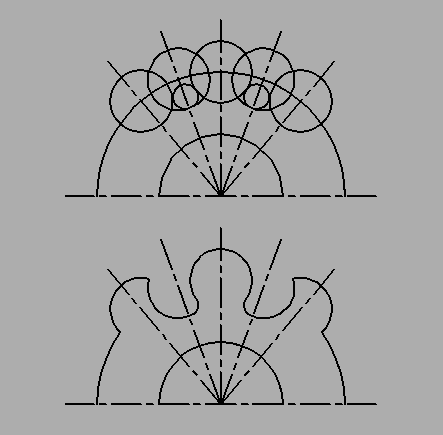
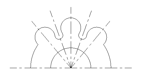
Hello everyone. You need to select several sizes and align the extension lines to the short line of each selected size. Maybe there is such a program?
-

drawing problem ,
riah replied to riah's topic in AutoCAD 2D Drafting, Object Properties & Interface
-
Solidworks VBA for renaming components in an assembly
SLW210 replied to dnenad's topic in SolidWorks
From what I quickly look into on the Dassault Systems (SolidWorks) site, among other changes for SolidWorks 2025 API, there was a change in the methods for saving a drawing. My WAG is that's where the VBA is failing on SolidWorks 2025, could be another change as well. -

drawing problem ,
eldon replied to riah's topic in AutoCAD 2D Drafting, Object Properties & Interface
I would start by drawing five circles R10. Then two circles R4 using TTR. Then trim to suit.
-
We use point styles with markers (which are blocks) instead of separate entities (which are also blocks) to show utility equipment like hydrants and valves. At least, the surveyors do. The engineers turn off the markers and insert blocks nearby to reduce clutter. That seems clunky to me. I would like to be able to offset a marker, the way you can rotate a marker, and put it somewhere nearby. I get that you can't just add a property to a Civil3D object, so we'd add user-defined properties for X and Y. So far so good. Where I get stuck is changing the position of the marker in relation to the point. You can change the insertion point of the block, but that applies to every instance. Dynamic blocks might work, but there would have to be a way to protect the dynamic parameters and actions from anyone who tries to change the block. You'd have to adjust the rotation every time you changed the position, and vice versa. It seems like more trouble than it's worth, but if there's something simple I'm missing, I'd appreciate any suggestions.
-

drawing problem ,
CyberAngel replied to riah's topic in AutoCAD 2D Drafting, Object Properties & Interface
How far should the centers of the radius-10 circles be from the center? In other words, how do you place the tabs (or whatever you call those circular protrusions)? It looks like the left and right sides of the central tab are different. Should they be symmetric? Once you place the tab circles, you should be able to draw the radius-4 circles as tangent to two of the tabs. Then it's just a matter of trimming. Here's what I got with the tabs placed on the diameter-80 arc:
-
In the voronoi version some error checking before trying to call _polyline should be added indeed. And this function is dependent on how well the points are distributed over the line (ent->pts function). For the lines close together, more points should be given and with crossing lines it will not work at all. It only works if the lines stay in between the two polylines, and it doesn't in the example from OP:
-
Thanks. The animation in the GIF is from the calculations made in _cornerOffset. When it was (finally ) working I replaced the animation code with error checking. Didn't take the time to make it do both, but I did want to show how it worked here.
-
 Jarvis joined the community
 -
I think you're doing a very good job. PS: The animation in the GIF doesn't look the same as the one in the code.