All Activity
- Past hour
-
 ZPK104 joined the community
 -

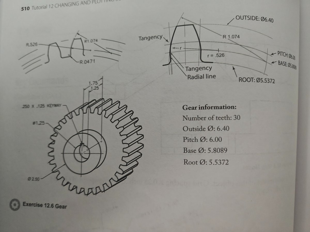
Help with 3D spur gear drawing (no tooth width given) !!
Nlevismith95 replied to Nlevismith95's topic in AutoCAD 3D Modelling & Rendering

-
 EmeraldSynth joined the community
 - Today
-
Help with 3D spur gear drawing (no tooth width given) !!
Nlevismith95 replied to Nlevismith95's topic in AutoCAD 3D Modelling & Rendering
Below is the radius I keep getting after using a 60 item polar array for the width. I then drew 3 point arcs from offset line to the pitch intersection and then the root. I think this is where I'm going wrong, but don't know how to correct it. -
 markevans66 joined the community
 -
Help with 3D spur gear drawing (no tooth width given) !!
Nlevismith95 posted a topic in AutoCAD 3D Modelling & Rendering
As the title states, I am trying my best to create this drawing for my AutoCAD class, but I am having no luck due to missing information and my lack of skills. This is the first module where we are covering 3D modeling so the textbook has been no help other than basic commands. What I am most frustrated with is not having the tooth width. I have started by drawing the diameters of the circles. Then I drew a line from center to outside most circle quadrant. From there I used polar array on the line with 60 items to hopefully get the tooth width or a way of drawing the arcs, but I am having no luck. I realize I am probably going about this wrong, so any help would be much appreciated. The lack of information in this class has been very frustrating for a beginner like myself. In what situation would I not have the tooth width when drawing? Why do I have to derive information when I'm just learning the software.... Anywho, please help me before I go insane. Thanks!!!!
-
Nlevismith95 joined the community
-
 CptOblivious joined the community
 -

Help Appreciated: Force Existing Layer Names to UPPER CASE Not Working
Clint posted a topic in AutoLISP, Visual LISP & DCL
Application: BricsCAD V26 Goal: To modify layer names to display as UPPER CASE from Title Case (Example: From existing layer name as "Trim" to "TRIM") Issues: As coded, the existing layer names in Title Case are not being processed. The confirmation message wrongly states that UPPER CASE was applied to the layer names when it was not. Help Needed: Please review the attached program and suggest needed edits. Resources My programming skills continue to grow. I am assembling snippets from various sources. Best regards, Clint UPPERCASE-LAYER-NAMES.lsp -
There are several fields with 1 decimal place. Is there a way to convert selected fields with 1 decimal place into fields with 2 decimal places without losing the connection of fields with objects? The field is 1 decimal place %<\AcExpr (3.1416*%<\_FldPtr 1317270971888>%^2/4*0.0785*%<\_FldPtr 1317270971632>%*%<\_FldPtr 1317270971472>%/10000) \f "%lu2%pr1">% The field is 2 decimal places %<\AcExpr (3.1416*%<\_FldPtr 1317157078864>%^2/4*0.0785*%<\_FldPtr 1317157078096>%/10000) \f "%lu2%pr2">% fields.dwg
-
 xtsebas65 joined the community
 -
Need a little more info than "gather coordinates from multiple places" how do you want to do that? and from what places? are these entity's in the drawing or txt/cvs files? like Jonathann3891 suggestion here is one lee made for polylines https://www.lee-mac.com/polyinfo.html Attach some sample drawings or files.
-
This might be much easier using a simple block and utilizing data extraction on said block.
-
 alp22 joined the community
 -
I need a lisp command that will allow me to gather coordinates from multiple places and then put that information into a table
-
 Arash.b joined the community
 -
 Ali Pandamooz joined the community
 -
Simply type in command line : TRIMEXTENDMODE and press enter, then change the value to "0"
-
 Siosan82 joined the community
 - Yesterday
-

cui panel image
BIGAL replied to mohammadreza's topic in The CUI, Hatches, Linetypes, Scripts & Macros
Do you have the paths set up correct for where your images are saved, check Support, Trusted and Icon paths in Options, Files. -

Excel VBA: 7 Functions for dealing with feet & inches in Excel
mhupp replied to phuynh's topic in .NET, ObjectARX & VBA
The problem I had with lambda's is getting them into a new workbook when I needed them. This VBA code will load them with a click/call. just need to convert quotes to double quotes. Sub LoadLambda() ActiveWorkbook.Names.add Name:="todec", RefersToR1C1:="=LAMBDA(imperial,[to_cFactor],LET(cf,IF(ISOMITTED(to_cFactor),1,to_cFactor),si,IF(LEFT(imperial,1)=""-"",-1,1),IF(ISBLANK(imperial),""n/a"",IF(ISNUMBER(imperial),imperial*cf,LET(ft,IFERROR(ABS(VALUE(LEFT(imperial,(FIND(""'"",imperial)-1)))),0),in,TRIM(SUBSTITUTE(SUBSTITUTE(IFERROR(RIGHT(imperial,LEN(imperial)-FIND(""'"",imperial)),imperial),""-"",""""),"""""""","""")),IFERROR(si*(ft*12+VALUE(IF(ISERR(AND(FIND("" "",in),FIND(""/"",in))),IFERROR(VALUE(""0 ""&in),in),in)))*cf,""n/a""))))))" ActiveWorkbook.Names("todec").Comment = "Convert various imperial format feet-inches to decimal with optional argument convert to-factor [cFactor]" End Sub -

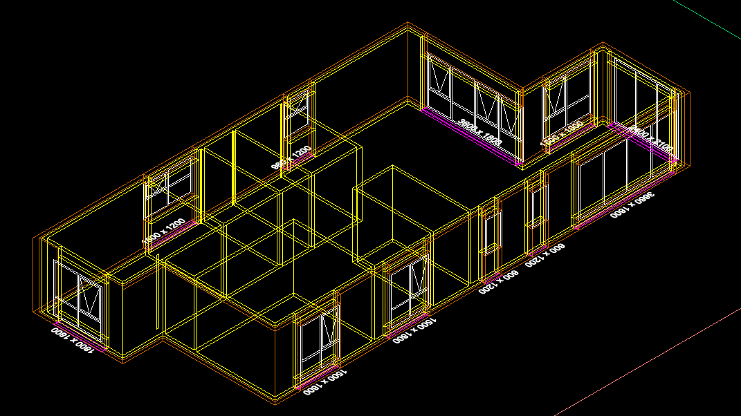
Rooftop and walls - two questions
danellis replied to katie.dim's topic in AutoCAD 3D Modelling & Rendering
What programme are you using, and what level of detail do you need to model to? If you're looking to produce construction-type drawings, then, as Remark said, you need to keep the tops of your walls flat but show other elements to achieve the junction. If you're using AutoCAD Architecture to produce less detailed/non-construction drawings, then it has a command to "extend wall to roof" (I think that's what it's called-try a right click on the wall) that will sort it for you. If you're using some other software, you'll have to investigate how that software works- hopefully your training material covers it, or google or someone here will. dJE -
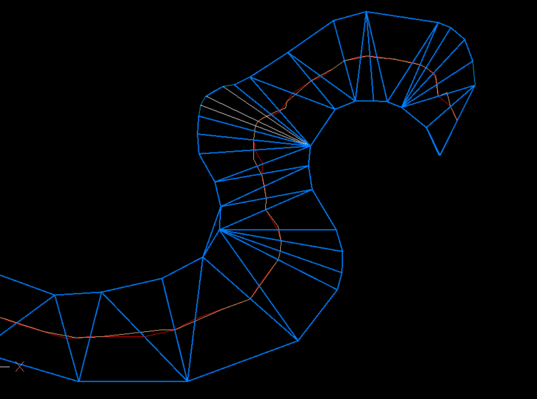
Ufff… I see a lot has happened in this thread since my last visit I’ve been busy with a couple of very urgent matters, but I’m going to try to catch up again. The results achieved by Dexus are very good. It seems there’s not much left to improve. Maybe getting a simpler and faster code? Also, the problem of the “recodos/inlet/recess” is still there: as long as there isn’t a code that can compute a centerline for two margins, whether they have recodos/inlets/recesses or not, there will continue to be thousands of unsuccessful searches for this problem on the web. I think finding a solution for this is a good goal. I’ll try to focus my next piece of code in that direction.
-
hello every body , I created a CUIX file in AutoCAD and set images for the panel icons, but their images don’t load and a question mark appears. The image format is PNG even i chaned that images to .bmp format but result is same ! whats the solution? (that problem doesn't occurs in all version.)
-
I don’t have a lot of lisp routines to test with, only the ones I use to benchmark with, they work, except _VL-TIMES is missing I was able to compile and load Python, most of the simple scripts I tested seem to work, on the fence on whether or not publish anything. There’s some weirdness preventing me from running my unit tests.
-

Rooftop and walls - two questions
oddssatisfy replied to katie.dim's topic in AutoCAD 3D Modelling & Rendering
To make walls reach the roof at an angle, you need to use a sloped wall or roof tool, or adjust the wall heights and vertices so each segment follows the desired slope. The white lines between joined boxes are internal edges or seams; to remove them, merge vertices, weld edges, or delete internal edges, and make sure all surfaces have the same material with smooth shading enabled so the lines no longer appear. -
Thanks LRM i do admit the task has a lot of posts and probably skipped over the one about using TIN's.
-
I worked on a package some 30+ years ago using lisp in Intellicad and there was no real problems, a couple of idiosyncrasies, that we had to recode around. No VL at that time, so don't know about current version if VL is supported, perhaps Daniel you can test. Intellicad quotes "he LISP interpreter is an internal API and can even be combined with the macro recording language mentioned above." The Autocad macro is at best useless if you want to edit it any serious way, I would like to know what code is produced by Intellicad if you could look at that as well. I have said before that one cad program macro from many years ago produced VBA code, much like Excel. This a similar example of Intellicad lisp package.
-
@BIGAL that was the essence of my suggestion about 100 posts ago (October 22). The results rely to heavily on the relative distribution of vertices (quantity and spacing) between the two polylines.
-
Just thought what would using a TIN, only drawback was TIN needed a lot of editing before joining mid points of mesh or lines. It is close to the orange linework. White lines are just that where TIN's have been removed.
-
Publish as PDF,Purge all and save as dxf binary 2007
BIGAL replied to pyou's topic in AutoLISP, Visual LISP & DCL
Have a look at (setq lays (layoutlist)) there is no Model in the list created saves a few if and buts. Can use also (setvar 'ctab "Model") so no Doc required.- 1 reply
-
- 1
-

- Last week
-

Penn Foster Student Suffering with Oleson Village Map!!!
ReMark replied to AutoCad Student's topic in Student Project Questions
What aspect of the project are you having difficulty with specifically? -

CIVIL 3D - CONVERT POINT CLOUD INTO SURFACE
CyberAngel replied to Carlo Point Cloud's topic in Civil 3D & LDD
As BigAl points out, you'll need to create a surface. An alignment may be helpful in locating things. Contours may help to locate the problem areas. Are the point clouds large, that is, do they cover the whole road? Or are they small, clustered on the damaged places only? Your workflow will be different depending on how much detail you have, how large the problem areas are, and the types and amounts of information you're expected to generate. -

Penn Foster Student Suffering with Oleson Village Map!!!
Jarvis replied to AutoCad Student's topic in Student Project Questions
yes, sorry it is the Oleson village project. I am in need of assistance started to project but having a hard time completing. -
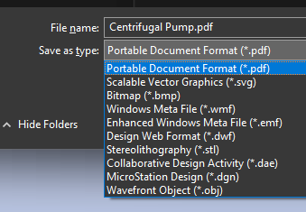
this is from the export command edit: I just realized I was playing with PE, and not PE-plus. I think the later has the 3d tools
.jpg.058d14723c93060f01b39796a4e4ec70.jpg)