All Activity
- Today
-

[LISP plugin] Omni Wheel-a custom radial menu tool
Steven P replied to VicoWang's topic in AutoLISP, Visual LISP & DCL
Could you put up a screen shot so we know what you want us to download - i'm very sceptical about just down loading unknown files. Better again would be the code to look at first of course. -

[LISP plugin] Omni Wheel-a custom radial menu tool
VicoWang posted a topic in AutoLISP, Visual LISP & DCL
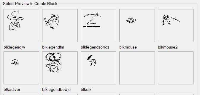
This is a radial menu tool that can be configured with up to 18 custom commands, accessed by double-clicking with the mouse. Installation method (upgradable in the future): [Omni Wheel] VCID: US87Y8 @ VedaCAD Note: To install via VCID, you need to install VedaCAD in advance and log in to a free account (or PRO account). -
Don't know about that.... ...not easy but because it was a quiet Christmas week last time... and if we can insert image buttons, we can insert custom button shapes: (just realised I have shamelessly not credited RLX? with the mouse) Suspect the same as SWL though, I'd be surprised if anything changes. BricsCAD is likely to maintain compatibility with AutoCAD and not go too far away... so 'BricsCAD' DCLs will work as 'AutoCAD' DCLs Colours and fonts would be handy... which is why I made up the first one, though Bold and Italic might be a better first step, and multiline text (I have a few with filepaths displayed where word wrapping would save me a few lines of coding). Not sure what else, but I am sure to think of something over the net week or so to add

-
 mostar joined the community
 -
You can handle that by separating the prefix from the numeric part of the ADDRESS attribute and sorting on the components rather than treating the whole value as a plain string. For example, L1-001, L1-002, L1-010 should be compared using L1 as the prefix and 001, 002, 010 as the numeric portion. The same idea works for something like 1/1/1-001, where the part before the final hyphen is the prefix. If the Lisp currently assumes that ADDRESS contains only digits, that's probably the part that needs changing. The important bit is to extract the number after the final -, convert that substring to an integer, and use it as the sort key. That will also preserve the expected order for values such as ...-002, ...-010, ...-100 instead of getting alphabetical ordering. If different prefixes need to be grouped together, I'd make the sort key something like (prefix, numeric part). That should let the same routine handle all three formats without having to hard-code L1 or 1/1/1.
-
 Jeffery2145 joined the community
 -
.thumb.jpg.615654602253be56b2fbd5d064834780.jpg)
Why does the same CAD drawing behave differently on two computers?
indiancad posted a topic in AutoCAD 2D Drafting, Object Properties & Interface
Both systems may have the same drawing, but the result can still be different. Fonts, SHX files, plot styles, support paths, and installed add-ons can change how the drawing behaves. This is why sending only the DWG file is sometimes not enough. For team projects, I usually keep the required support files together with the drawing. It makes troubleshooting much easier when another user opens the same file. What additional files do you always send with a DWG? -
You could always use VBA, and/ or .NET to make the User Forms and work the LISP. I have a VBA or 2 around that I did, one runs Scripts in AutoCAD, I'll have to see what the others may do as I really haven't used them in a while. The inbuilt one works for me for now, but always could use more options. Autodesk hasn't made meaningful improvements to LISP since 1999 for AutoCAD 2000 and as you stated 0 DCL in 40 years, so don't get your hopes up on BricsCAD picking up the torch. Worth a try I would imagine.
-

Why does Object Snap sometimes stop working correctly in CAD?
SLW210 replied to indiancad's topic in AutoCAD 2D Drafting, Object Properties & Interface
Shift + Right-Click brings up a menu, except for Geometric Center, they all have a 1 letter shortcut, once in the habit it is very fast to select the snap you need. -

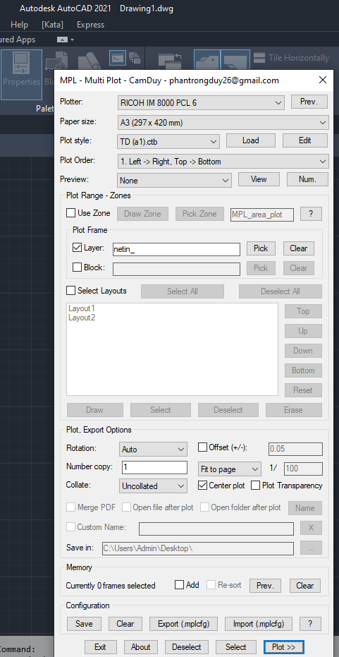
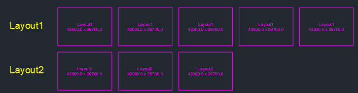
Free Multi Plot Lisp – Fast Batch Printing for AutoCAD, BricsCAD & ZWCAD | Model/Layout, Zone Plotting & PDF Merge
CamDuy replied to CamDuy's topic in AutoLISP, Visual LISP & DCL
I am still using it with AutoCAD 2021.
-

AutoCAD 2027.1 Now Available: Smarter Autodesk AI Assistance and Smoother Collaboration
animal1103 replied to The AutoCAD Blog's topic in AutoCAD Blogs
-

Free Multi Plot Lisp – Fast Batch Printing for AutoCAD, BricsCAD & ZWCAD | Model/Layout, Zone Plotting & PDF Merge
Nikon replied to CamDuy's topic in AutoLISP, Visual LISP & DCL
The code doesn’t work (Autocad 2021 localized ) command: MPL Unknown command "MPL" -
Free Multi Plot Lisp – Fast Batch Printing for AutoCAD, BricsCAD & ZWCAD | Model/Layout, Zone Plotting & PDF Merge
CamDuy replied to CamDuy's topic in AutoLISP, Visual LISP & DCL
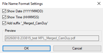
2026/08/18 - Version V13: Added Custom Name and Draw Temp Layout features Link Drive: https://drive.google.com/file/d/1McaDZI-gqSdi3zAdaHNu5LQ14_2JsDOj/view?usp=sharing
-
Designing UIs on the legacy DCL is basically dancing on a tightrope. It's a shame—even if there are new features, I can't use them in VedaCAD due to the need for cross-platform and full-version compatibility. If we really need a new feature, I think it should be native support for rounded buttons.
-
Since Acad first introduced DCL's that is like 40+ years ago, there has been no improvements to DCL's. This may be a big opportunity for Bricscad to add some more features. A few obvious ones. Text color Text style Text size Using other methods like .Net, VBA and maybe Open dcl the latter I don't use, allow for some of the options to be used. Obviously it's a support request, given that Bricscad has added VL functions not in other software, then maybe some new dcl options would be good. A proper forms engine would be good. So before sending a support request any other suggestions ? Hopefully more support requests will follow.
- Yesterday
-

Why does Object Snap sometimes stop working correctly in CAD?
BIGAL replied to indiancad's topic in AutoCAD 2D Drafting, Object Properties & Interface
Why not just, saved in a startup lisp. (defun C:15 ()(setvar "osmode" 15359)) ; sets all snaps on (defun C:47 ()(setvar "osmode" 47)(setvar "AUNITS" 0)) (defun C:99 ()(setvar "osmode" 99)) (defun C:8 ()(setvar "osmode" 8)) (defun C:9 ()(setvar "osmode" 9)) (defun C:0 ()(setvar "osmode" 0)) Ok, a little unknown tip is say you type Line you can then type '47 note apostrophe this runs a transparent command inside the Line command, setting the osmode to be used. Or type the number to set your osnaps. In lisp use (setvar 'osmode 47) before executing "do something". -

Why does Object Snap sometimes stop working correctly in CAD?
CyberAngel replied to indiancad's topic in AutoCAD 2D Drafting, Object Properties & Interface
You can examine your snap settings in the Drafting Settings dialogue box, under the Object Snap tab. The other tabs are useful too. Open this dialogue by typing DSETTINGS at the command prompt. Hint: if you type +DSETTINGS and give it 2 for the Tab Index, it will open at the Object Snap tab. Another way to open this dialogue is by expanding the Snap Mode menu on the status bar (you may need to enable it from the Customization button there). On that same menu you can toggle any of the snap options without going to the dialogue. You may want to keep certain object snaps turned off. With too many active, it can be hard to locate the right point. If you need one of those snaps temporarily, you can override the setting by typing a shortcut, such as PER for Perpendicular or NON for None. Here is an Autodesk video that covers object snaps. There is much more information out there about object snaps and settings. -
Why does Object Snap sometimes stop working correctly in CAD?
indiancad posted a topic in AutoCAD 2D Drafting, Object Properties & Interface
If your object snap is not working properly or it feels like it is missing points, do not worry. In most cases, the problem is very simple. First, check the system variable called OSMODE. OSMODE controls which object snap options are turned ON or OFF. For example, it controls snaps like endpoint, midpoint, center, intersection, and others. If the value of OSMODE is changed or set incorrectly, your snaps may not work as expected. You may feel like CAD is not snapping at all or only snapping sometimes. To check it, just type OSMODE in the command line and press Enter. CAD will show you the current value. If needed, you can change it to enable the snap modes you want. After setting it correctly, your object snaps should start working normally again. Have you ever fixed a CAD problem just by changing a system variable? Which one helped you the most? -
 Green Releaf Dispensary joined the community
 -
 Asad Ullah Khalid joined the community
 -
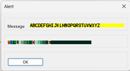
import wx import random from pyrx import Ap, Db, Ed, Gs class TestDialog(wx.Dialog): def __init__(self, parent, size, pos): wx.Dialog.__init__(self) self.Create(parent, wx.ID_ANY, "", pos, size, style=wx.BORDER_NONE) self.width = size.GetWidth() self.height = size.GetHeight() self.static_bitmap = None self.image = None self.raw_data = None self.offsets = [0] * self.width self.bg_r = 0 self.bg_g = 0 self.bg_b = 0 self.timer = wx.Timer(self) self.Bind(wx.EVT_TIMER, self.on_melt_tick, self.timer) def setImage(self, img: wx.Image): self.image = img self.raw_data = bytearray(self.image.GetData()) if len(self.raw_data) >= 3: self.bg_r = self.raw_data[0] self.bg_g = self.raw_data[1] self.bg_b = self.raw_data[2] bmp = wx.Bitmap(self.image) if not self.static_bitmap: self.static_bitmap = wx.StaticBitmap(self, wx.ID_ANY, bmp, pos=(0, 0)) else: self.static_bitmap.SetBitmap(bmp) self.static_bitmap.Bind(wx.EVT_LEFT_DOWN, self.on_click) self.timer.Start(33) def on_melt_tick(self, event): stride = self.width * 3 melted_anything = False for x in range(self.width): if self.offsets[x] < self.height: increment = random.randint(2, 8) self.offsets[x] = min(self.height, self.offsets[x] + increment) melted_anything = True offset = self.offsets[x] if offset == 0: continue x_offset = x * 3 for y in range(self.height - 1, offset - 1, -1): target_idx = (y * stride) + x_offset source_idx = ((y - offset) * stride) + x_offset self.raw_data[target_idx] = self.raw_data[source_idx] self.raw_data[target_idx + 1] = self.raw_data[source_idx + 1] self.raw_data[target_idx + 2] = self.raw_data[source_idx + 2] for y in range(offset): bg_idx = (y * stride) + x_offset self.raw_data[bg_idx] = self.bg_r self.raw_data[bg_idx + 1] = self.bg_g self.raw_data[bg_idx + 2] = self.bg_b if not melted_anything: self.timer.Stop() return self.image.SetData(bytes(self.raw_data)) self.static_bitmap.SetBitmap(wx.Bitmap(self.image)) def on_click(self, event): self.timer.Stop() self.EndModal(wx.ID_OK) @Ap.Command() def doit(): doc = Ap.curDoc() db = doc.database() wxDoc: wx.Window = doc.getWxWindow() sz = wxDoc.GetSize() pos = wxDoc.GetScreenPosition() img: wx.Image = Gs.Core.getBlockImage(db.modelSpaceId(), sz.GetWidth(), sz.GetHeight(), 1.0) dlg = TestDialog(wxDoc, size=sz, pos=pos) dlg.setImage(img) dlg.ShowModal() dlg.Destroy()
-
- 1
-

- Last week
-
My drawing disappeared — what do you check first?
BIGAL replied to indiancad's topic in AutoCAD 2D Drafting, Object Properties & Interface
My $0.05. ZOOM E zoom c (getvar 'extmax) 100 May need a different scale than 100 If ok then zoom c (getvar 'extmin) 100 -
 EduLos joined the community
 -
My drawing disappeared — what do you check first?
indiancad posted a topic in AutoCAD 2D Drafting, Object Properties & Interface
Have you ever opened a DWG and suddenly thought, “Where did my drawing go?” The objects may still be there, but they could be far from the current view, on a turned-off layer, or hidden inside another location. Here are a few quick things I usually check: Zoom Extents to see if the drawing is just far away from the current view. Layer visibility (make sure layers are not frozen or turned off). Check if objects are on a hidden or locked layer. UCS / View settings in case the view is rotated or shifted. Drawing units & scale to ensure objects aren’t extremely small or large. Use SELECT ALL to confirm objects still exist in the file. I usually start with Zoom Extents first, then move through the rest. I usually start with Zoom Extents first, then move through the rest. What do you check first when your drawing suddenly disappears? -

AutoCAD Layer Properties Manager Tools: Tuesday Tips With Frank
The AutoCAD Blog posted a topic in AutoCAD Blogs
It’s time to revisit the Layer Properties Manager Palette. There are so many things to discuss in this palette, many of which are overlooked. From our training days to our daily work, we’re generally focused on the table of layers and properties. Oh, but there’s so much more. Previously in this blog, I’ve discussed the tools found to the left of the table. One was about creating and using Layer Filters, and then another about Layer States (links included for your convenience). Today’s post focuses on the columns of the table. I’m again using the Floor Plan sample file and in a Layout Tab so that all of the VP columns are displayed. Property Column Tools By default, the layer property columns appear as they do in the image below. They appear condensed and generally hard to read. You’ve probably already figured out that you can sort the table in an ascending or descending manner based on a column. Simply click that column header (as shown below) to sort. The up or down arrow will be your visual cue. Also, double-clicking on the right edge of a column will expand that column to its optimized state. I’ll get back to what that means in a moment, but again, the animation below shows it in action. The Right-Click Menu That last nugget is indeed handy, but in a layout view, there are 19 columns – hardly an efficient way to handle the task. That’s where the right-click menu comes in. Just hover over any column header and right-click. You’ll be presented with the menu as shown in the following image. In the top and bottom sections, you’ll see each column with a check mark beside it, indicating it’s displayed (the bottom VP columns won’t appear in Model Space). Don’t need a property column? Turn it off by clicking on the name. Are you a CTB office? If so, the Plot Style column just takes up space, so you can turn it off here. Let’s turn our focus to the middle section of the menu. Here, we have tools to Maximize or Optimize all columns, or only the one you right-clicked on. What’s the difference? Maximize changes the width of all columns to fit the column headers and the data content. Optimize changes the width of all columns to fit the content in each column. You can see the effect of each in the image below. Below these four tools is one more that is labeled as either Freeze or Unfreeze column. Please note that with this command, it does matter which column header you right-clicked on, so keep that in mind. Also note that by default, the Status and Name columns are frozen. What does this mean exactly? Freeze keeps the column, and any columns to the left, visible while scrolling. Unfreeze it so that all columns scroll. Let’s say I need to see the On and Frozen status while I’m way off in the far right side of the palette. The animation below will show you the workflow and the results. That’s a lot of power, and since these tools aren’t used all the time, you might forget about what they do exactly and royally mess up your palette. Don’t worry, there’s also a restore all to default tool for just such an occasion. There’s just one more tool on the right-click menu. You may have noticed one called Customize… right below the standard column names. Clicking it will display the dialog shown below. Now, here at Tuesday Tips HQ, we pride ourselves on minimizing picks and clicks. My tip for you then is to use the method described above to display your desired columns. Otherwise, you’re just adding unnecessary clicks to your workflow. I guess if you wanted to turn off multiple columns at once, this would be more efficient, as the right-click menu dismisses once you select one to display or not, but since I’ve never done that in my four decades of using AutoCAD, I doubt you will either. Or I might be wrong – that I do know that I’ve done in that time frame. Until Next Time It’s not unlikely that I’ll see you again in the future with even more AutoCAD Layer Properties Manager tips, as there’s a lot of functionality in there. Meanwhile, don’t forget to review the Layer Filters and Layer States tips. There’s a lot there that can improve your overall efficiency. More Tuesday Tips Check out our whole Tuesday Tips series for ideas on how to make AutoCAD work for you. The post AutoCAD Layer Properties Manager Tools: Tuesday Tips With Frank appeared first on AutoCAD Blog. View the full article -
Does anybody else have this DIMBREAK issue?
SLW210 replied to SLW210's topic in AutoCAD Bugs, Error Messages & Quirks
DIMBREAK>Remove works but is tedious, then I have to rebreak them. Still stumped on what caused this in these drawings, not all of the dimensions with DIMBREAKs froze like this. I came up with a LISP to remove all DIMBREAKs in a drawing, now I just need redo the dimensions that need breaks. Also, I believe all of the dimensions with issues were broken by an object, those that were not having issues were broken by other dimensions. -
Does anybody else have this DIMBREAK issue?
SLW210 posted a topic in AutoCAD Bugs, Error Messages & Quirks
I have some drawings with issues with DIMBREAK. While working in the drawing and creating the dimensions, then breaking them, I have no issues, but after saving and closing then opening these drawings I did a few weeks ago and modifying, moving, deleting objects that break the dimension, the gaps remain. So far it's just been these few drawings I am modifying, I haven't reproduced the issue yet. Probably a long shot that it's happened to anybody else, but it has me stumped as to how this happened. I have just created new dimensions and all is fine now. I guess just a weird fluke. DIMBREAK Issue R14.dwg DIMBREAK Issue.dwg
-
Generating a Profile for a 147km Project
CyberAngel replied to Butterstone's topic in Civil 3D & LDD
I've done this before, when I had centerline elevations but not much else. Import the points. Connect them with a polyline (the CNCPT command may help). This polyline will be helpful in the next step, so don't erase it when you create your alignment. Offset the centerline (that polyline we talked about) about two feet. Connect one end, Join it to the sides, and Close the polyline so you have a border. Create a surface using your points and that border. Define a profile with the new surface and the alignment. When you have styles for the profile view and the labels the way you want them, add them to a template so you don't have to go through that process again. Edit: Sorry, the CNCPT command is a third-party product, i.e. it costs money. That was the first result from Goggle. You can use the 'PN command instead (don't forget the quote) if your points are numbered to match the progress of the path. -
Azimuth and Distance with Drawn out Leaders Dimensioning on Civil 3D 2018
CyberAngel replied to Butterstone's topic in Civil 3D & LDD
You can create a label style that looks like what you want. You can use Annotation | Add Multipurpose Labels | Multiple Segment to create labels, all at once, for every segment of a polyline. How you drag them away from their segments, I don't know. Maybe isolate them and use the stretch command on a linear bunch at a time. -
 SionCV joined the community
 -
Reload LineTypes in AutoCAD 2027 not working?
SLW210 replied to Aftertouch's topic in The CUI, Hatches, Linetypes, Scripts & Macros
So instead of fixing this issue, there's a workaround. Thanks for getting back!