All Activity
- Past hour
-

Lee-Mac NumInc modify to accept reset values
dober replied to pbelon's topic in AutoLISP, Visual LISP & DCL
Such a tool would be https://www.theswamp.org/index.php?topic=58808.0 -

2025 Draw Hatch in lisp or using command line
Lee Mac replied to Strydaris's topic in AutoLISP, Visual LISP & DCL
Try using (initcommandversion) before the command call. - Today
-

Attention fellow Penn Foster structural drafting students....
TimC posted a topic in Student Project Questions
Alright guys, so far my cad experience through Penn foster has been pretty rough to say the least...lol...starting the Structural Drafting portion now. Anything I should be aware of? Any input would be appreciated. -

2025 Draw Hatch in lisp or using command line
Strydaris posted a topic in AutoLISP, Visual LISP & DCL
Hi everyone, I am using ACAD2025LT and I was looking into the newer "Draw" hatch feature, where you can type hatch and tell the command that you want to draw a hatch along a sort of polyline that you pick. You can pick Alignment, Width whether its going to be just a rectangle or circle etc etc. The only thing I can seem to figure out is if this can be access using LISP. I have a few idea for hatching as I create something using LISP, but for the life of me I cant figure out how to use the draw hatch feature with lisp. I know lisp forces the use of "-" on a command when used in a lisp routine. Like if you use (command "hatch" ) in a LISP it will actually do (command "-hatch"). Although if you use -hatch you are given a whole different set of options to pick from and the "draw" option is not there. So my question is, Has anyone been able to use this draw option in a LISP routine? Thanks. -
Lee-Mac NumInc modify to accept reset values
Lee Mac replied to pbelon's topic in AutoLISP, Visual LISP & DCL
Unfortunately not with the current version, but I'll certainly consider implementing this functionality in a future version. -
 Guru1337 joined the community
 -

Pline Script File Keeps Failing
eldon replied to Rayan O's topic in The CUI, Hatches, Linetypes, Scripts & Macros
Have you tried to turn off Object Snaps before you run the script? It looks to me as if your line is snapping to adjacent end of line points instead of plotting the listed coordinates. -
¿It's posible to reset counter each time previous counter increments?. For example: 1-1-a, 1-1-b, 1-1-c, 1-2-a, 1-2-b, 1-2-c, 1-3-a, 1-3-b .... etc
-

Pline Script File Keeps Failing
SLW210 replied to Rayan O's topic in The CUI, Hatches, Linetypes, Scripts & Macros
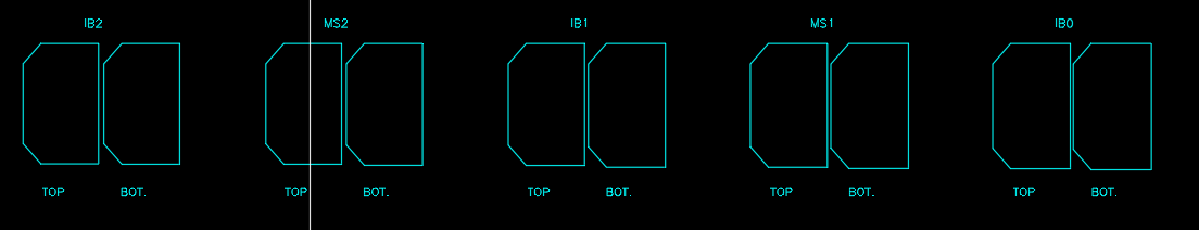
I moved your thread to the The CUI, Hatches, Linetypes, Scripts & Macros Forum. Your script is missing the blank line at the bottom, so it needed that for enter at the end. Other than that, I ran it in AutoCAD 2000i on my home computer and they all look like your bottom image. -
 Camille joined the community
 -
 abdu_mandala joined the community
 -
 JAW_NZ joined the community
 - Yesterday
-
 Phenomxy joined the community
 -
 Jhonatan joined the community
 -

Pline Script File Keeps Failing
Rayan O posted a topic in The CUI, Hatches, Linetypes, Scripts & Macros
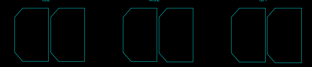
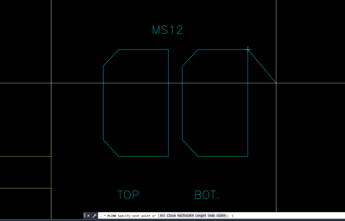
I have multiple sections which I am trying to plot using a script file. I am stuck although the format seems to match what I can find online. This is what the shapes look like when I run the script file weirdly enough. the last 5 sections work just fine. I know the coordinates are correct in all cases since I made a scatter plot in Excel before hand. Also, when I just copy the lines from the script file into the command line. I get the right shape every time. (Possible Clue: the command stays in pline after pasting, look at the command line) Lines pasted into command line _.PLINE 103150,-122340 103150,-126391.3 101272.9,-126391.3 100691.9,-125765.9 100691.9,-122965.4 101272.9,-122340 103150,-122340 C _.PLINE 106150,-122340 106150,-126391.1 104264.2,-126391.1 103674.6,-125755.4 103674.6,-122975.7 104264.2,-122340 106150,-122340 C sections.scr
-
Rayan O joined the community
-
 Igor vos joined the community
 -
 mariajarwan joined the community
 - Last week
-
Just doing something wrong with using OBDX still getting my head around using it. I think the limitation is in getting an object via a selection set. So a script approach may be the easiest way. Give this a try two parts the doatts.lsp file which does the work, the c:doatts that makes the script to be run so need to load that first. That means 2 lisp files. Change the Acadtemp to your start directory, pick any dwg for directory name. (defun c:doatts ( / fname files pre fo) (setq fname (getfiled "Select a Dwg FILE" "d:\\Acadtemp" "dwg" 16)) ; chnage start directory name (setq pre (car (fnsplitl fname))) (setq files (vl-directory-files pre "*.DWG" 0)) (setq fo (open (setq fname (vl-filename-mktemp "" "" ".scr")) "w")) (write-line "(command \"regen\")" fo) (foreach file files (write-line (strcat "Open " "\"" pre file "\"") fo) (write-line "(load \"doatts\")" fo) (write-line "(AH:doatts)" fo) (write-line "close Y" fo) ) (close fo) (command "script" fname) (vl-file-delete fname) (princ) ) Second lisp is the doatts defun AH:doatts ( / ss obj atts att tname) (setq ss (ssget "X" '((0 . "INSERT")))) (repeat (setq x (sslength ss)) (setq obj (vlax-ename->vla-object (ssname ss (setq x (1- x))))) (if (= (vlax-property-available-p obj 'hasattributes) T) (progn (setq atts (vlax-invoke obj 'Getattributes)) (foreach att atts (setq tname (vlax-get att 'Tagstring)) (if (= tname "MATERIAL") (vlax-put att 'Textstring "TEST") ) ) ) ) ) (command "close" "Y") (princ) )
-

zwcad SHX Text Not Editable in PDF
Dahzee replied to CHAKRADHAR's topic in AutoCAD Drawing Management & Output
In PDF-XChange Editor, I could only edit the Title Border Text. All the node text isn't editable. Using OCR in PDF-XChange, it converted all 5 pages in about 15 seconds. I am using the paid-for version, so not sure if OCR is available in the free version. -
I will sometime soon, I will have to redownload ACAD at home to upload anything. Not my primary CAD for personal use by any means. But I will have a mockup that should show what I would like. If needed, I'll do a video explanation as well so that it is more clear.
-
zwcad SHX Text Not Editable in PDF
SLW210 replied to CHAKRADHAR's topic in AutoCAD Drawing Management & Output
I opened your PDF in Acrobat Pro and the text was editable. This seems to be a Foxit issue, though as mentioned, you might want to use a TTF font if that's what Foxit needs. ArialNarrow.ttf is a common replacement IIRC to ISOCP.shx -

zwcad SHX Text Not Editable in PDF
BIGAL replied to CHAKRADHAR's topic in AutoCAD Drawing Management & Output
Just do a google you should be able to find a ISO.TTF font there are thousands of fonts out there. You open c:\Windows\fonts and drag the TTF onto it from memory. ISO3098B ? If your lucky some one may have one already. -
Vehicle Tracking - where to find details for vehicles
BIGAL replied to Adam - Inspire's topic in Autodesk Software General
Like a lot here just remember teaching your children how to drive, no did not crash into things, but went around a roundabout, hands everywhere trying to turn, change gears and me praying as we chugged out. -
Can you post a sample drawing with a block example of before & after? Add explanatory notes to the drawing so that we understand. From what I can understand of your goal I think Lee's code will work without modification.
-
zwcad SHX Text Not Editable in PDF
SLW210 replied to CHAKRADHAR's topic in AutoCAD Drawing Management & Output
I can do that most of the time with the OCR (Optical character recognition) in Adobe Acrobat Pro. I thought Foxit has an OCR. -
I did just try this out, to no avail. I'm thinking I may have to do a lot of learning to solve this problem. Currently I'm thinking it may work the best to piggyback off of Lee's code so that the structure is there, and add the capability that I want. How complex that will be, I have no clue, but I suspect that I'll be learning a lot.
-
Blocks are one of the most powerful productivity features in AutoCAD. They allow you to combine multiple objects into a single, reusable element, making your drawings cleaner, more consistent, and easier to manage. Whether you’re working with symbols, parts, detail views, or title blocks, blocks help you work faster and more accurately. In this final installment of the AutoCAD Foundation series, we’re exploring how to insert a block and more. What Is a Block? A block is a collection of one or more objects combined into a single object. Once created, that block can be inserted multiple times into a drawing as individual block references, all tied back to the same underlying definition. You’ll commonly see blocks used for items such as: Furniture and fixtures Mechanical or electrical symbols Standard parts and components Detail callouts and title blocks Examples of blocks Using blocks offers several key advantages. Blocks help maintain consistency across drawings by ensuring uniformity for repeated elements such as symbols, parts, and title blocks. They also make editing and placement faster, since blocks can be inserted, rotated, scaled, moved, and copied much more efficiently than working with individual objects. Any changes made by editing or redefining a block are applied instantly to all of its references in the drawing. You can also include data such as part numbers, costs, service, dates, and performance values to blocks. The data is stored in special objects called block attributes. Finally, using multiple block references instead of duplicating object geometry helps reduce overall drawing file size. How to Insert a Block There are four key items involved when inserting a block into a drawing. #1. Block Definition This data is stored in a drawing file or drawing template file in a non-graphical format. Block definitions can easily be created or imported from any drawing file. Multiple block definitions can be created in a drawing file. Note: Block definitions don’t always need to be created just in the drawing that they will be used. A drawing file itself can represent a block definition that can be shared with other designers and inserted into any open drawing file. #2. Block Reference When you insert a block, you specify which block definition to create an instance or block reference from. The graphics for the block reference are drawn based on the block definition. A drawing file can also be inserted into an open drawing, when this happens a block definition based on the geometry in model space of the drawing file being inserted is created in the target drawing and then a block reference is created. #3. Block Insertion or Base Point When you insert a block, you specify an insertion point for the block in the drawing. The insertion point is based on the block’s base point, this is the point of the block reference attached to your cursor. The base point is circled on the block below. Later, if you select a block that’s already been inserted, it displays a grip at the base point. You can easily move and rotate this block using this grip. #4. Block Insertion Tool Several different block insertion tools are available in AutoCAD including: Block gallery on the ribbon Blocks palette Tool Palettes window DesignCenter These block insertion tools allow you to insert block references from the definitions created within the current drawing as well as insert drawing files stored on your local workstation or a shared network location. See How to Insert a Block Keep Going Ready to try out how to insert a block for yourself? Check out the AutoCAD Foundations page with exercises to get started. The post How to Insert a Block: AutoCAD Foundations appeared first on AutoCAD Blog. View the full article
-

zwcad SHX Text Not Editable in PDF
CyberAngel replied to CHAKRADHAR's topic in AutoCAD Drawing Management & Output
You may not have a choice here, but can you convert your text to TTF from SHX? PDF should accept that as text. -

AL's Steel Mill not working on BricsCAD
Clint replied to Jgrand3371's topic in AutoLISP, Visual LISP & DCL
This LISP routine works well up to the latest BricsCAD version as of this reply post date. Clint -
Do you have AutoSketch? What program are you using to make the cutting path? What file types can you save as or export? You may have to just redraw everything in a more compatible, newer CAD software. Many have a free trial. What compatibility mode are you running it in? You might try an older Windows in an older computer or a virtual box, if you feel that could be the issue.
-

Vehicle Tracking - where to find details for vehicles
Steven P replied to Adam - Inspire's topic in Autodesk Software General
Took the day yesterday to work through the examples, youtube and so on, a bit of trial and error and kid of got it working. Just need to practice more - it wasn't as bad as it looked at first Driving however is another thing. Still crashing into things. -
In ZWCAD 2026, our drawing uses isocp.shx font inside block attributes. When exporting to PDF, the SHX text is converted to geometry and becomes non-editable in Foxit. Is there any way to export SHX text as real editable text without changing the drawing font standard? text issue.dwg without sign 1.pdf
-
How to override text formatting
BIGAL replied to GrahamT's topic in AutoCAD 2D Drafting, Object Properties & Interface
You have a Table in your images, you can change all or one cell in a table with respect to the font style. Is that what your asking for ? If so post an example table dwg. Something like this (vla-SetTextStyle Objtable (+ acDataRow) "Arial") in a lisp.