All Activity
- Past hour
-

SELECT TEXTS OTHER THAN 3.5..HELP
leonucadomi replied to leonucadomi's topic in AutoLISP, Visual LISP & DCL
thanks master -

SELECT TEXTS OTHER THAN 3.5..HELP
Steven P replied to leonucadomi's topic in AutoLISP, Visual LISP & DCL
Ahh, that's my mistake, try this: (defun c:test (/ old_err EscVP StrScale2 TxtHt StrScale ss) (setq old_err *error*) (defun *error* ( a / ) ;; Add here return cmdecho to as it was, cmdecho 1 (princ "") (setq *error* old_err) (princ) ) ; End Error Defun (setvar "cmdecho" 0) ; perhaps record the state of cmdecho before here, and reset to that value at the end (if (and (setq EntVP (car (entsel "\Seleccione VIEWPORT: "))) (= (cdr (assoc 0 (entget EntVP))) "VIEWPORT") ) ; end and (progn (setq EscVP (vla-get-CustomScale (vlax-ename->vla-object EntVP))) (setq StrScale2 (rtos (* 3.5 (/ 1 EscVP)) 2 1)) (setq TxtHt (* 3.5 (/ 1 EscVP)) ) ; a number not a string ;; added this (setq StrScale (rtos (/ 1 EscVP) 2 2)) (setq vpnum (cdr (assoc 69 (entget EntVP )))) (vl-cmdf "_.mspace") (setvar "CVPORT" vpnum) (setq ss (ssget (list '(0 . "TEXT") '(-4 . "<>") (cons 40 TxtHt))) ) ;; corrected line ;;What are you doing with ss now? (Prompt (strcat "\nLa escala de La Ventana es 1/" StrScale)) (princ "\nLos textos de 3.5 en el interior de la ventana deben ser de: ") (princ StrScale2) ) ; end progn ) ; end if (setvar "cmdecho" 1) (princ) );fin defun - Today
-

How to correctly extract nested objects from blocks with scaling/mirroring)
SLW210 replied to p7q's topic in AutoLISP, Visual LISP & DCL
Maybe something in my post or the one of Lee Mac's I linked... -
Thank you. I'll give it a try. Also found an interesting topic here that might help me achieve the kind of list I wanted. https://www.cadtutor.net/forum/topic/70713-add-itens-to-a-sublist/
-
SELECT TEXTS OTHER THAN 3.5..HELP
leonucadomi replied to leonucadomi's topic in AutoLISP, Visual LISP & DCL
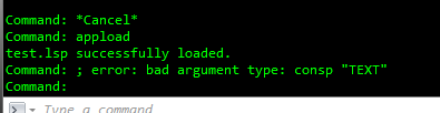
Master I'm trying the modified routine and this happens... (defun c:test (/ old_err EscVP StrScale2 TxtHt StrScale ss) (setq old_err *error*) (defun *error* ( a / ) ;; Add here return cmdecho to as it was, cmdecho 1 (princ "") (setq *error* old_err) (princ) ) ; End Error Defun (setvar "cmdecho" 0) ; perhaps record the state of cmdecho before here, and reset to that value at the end (if (and (setq EntVP (car (entsel "\Seleccione VIEWPORT: "))) (= (cdr (assoc 0 (entget EntVP))) "VIEWPORT") ) ; end and (progn (setq EscVP (vla-get-CustomScale (vlax-ename->vla-object EntVP))) (setq StrScale2 (rtos (* 3.5 (/ 1 EscVP)) 2 1)) (setq TxtHt (* 3.5 (/ 1 EscVP)) ) ; a number not a string ;; added this (setq StrScale (rtos (/ 1 EscVP) 2 2)) (setq vpnum (cdr (assoc 69 (entget EntVP )))) (vl-cmdf "_.mspace") (setvar "CVPORT" vpnum) (setq ss (ssget (list(0 . "TEXT") (-4 . "<>") (cons 40 TxtHt))) ) ;;What are you doing with ss now? (Prompt (strcat "\nLa escala de La Ventana es 1/" StrScale)) (princ "\nLos textos de 3.5 en el interior de la ventana deben ser de: ") (princ StrScale2) ) ; end progn ) ; end if (setvar "cmdecho" 1) (princ) );fin defun
-

Geometric center of open polyline, line
lrm replied to maahee's topic in AutoLISP, Visual LISP & DCL
@maahee It is not clear what you want to calculate. Please respond to the following questions. Should the program be able to handle lines? ... lwpolylines without arc segments? ... lwpolylinese with arc segments? arc objects? circle objects? If the open/close property of a polyline is "open" sould the polyline be considered a closed shape defined by a line segment from the last vertex to the first vertex? The code in your last post dows nothing if the object is not a line. If it is a line it adds a dim line but does not identify the "center". -

Extract vertices from a 3DSolid using ACIS data.
dexus posted a topic in AutoLISP, Visual LISP & DCL
Hello everyone, I'm trying to extract points/vertices from a 3D solid. The first way I tried was by exploding it into lines and arcs and then collecting the points. This works, but it is very slow. After that I found ACISdecode function by Kailas Dhage and used it to get some information about the 3D Solid. On a lot of 3D Solid it works and extracts the points correctly. But sometimes if I move the object, the point's inside of the ACIS data don't move. I'm trying to find where the transformation is stored so I can apply it to the exported points as well, but can't seem to find it. Code to export the points below, and an example drawing attached on which it doesn't work correctly. Hope someone can guide me in the right direction! (defun c:solid->pts ( / ent enx i rtn _acis) (defun _acis (enx / itm lin dxf str cha rtn) ; ACISdecode by Kailas Dhage (kailas@uts.com) ; Newsgroups: autodesk.autocad.customization 1999/05/10 ; Modified to work directly on entget data by dexus 2025/08/11 (while (setq dxf (assoc 1 enx)) (setq str (reverse (vl-string->list (cdr dxf))) itm nil lin nil) (while str (setq cha (car str) str (cdr str)) (cond ((= cha 95)) ((= cha 86) (setq itm (cons 73 itm))) ((= cha 32) (setq lin (cons (if itm (vl-list->string itm) "") lin) itm nil)) ((boole 6 cha 95) (setq itm (cons (boole 6 cha 95) itm))) ) ) (setq rtn (cons (cons (if itm (vl-list->string itm) "") lin) rtn) enx (cdr (member dxf enx))) ) (reverse rtn) ) (if (and (setq ent (car (entsel))) (setq enx (entget ent)) ) (foreach i (_acis enx) ; Princ result of the ACIS decode (princ "\n") (princ (vl-prin1-to-string i)) (if (and (equal (car i) "point") (> (length i) 5) (setq i (cddddr i))) (entmakex (list '(0 . "POINT") (cons 10 (list (distof (car i)) (distof (cadr i)) (distof (caddr i)) ) ) ) ) ) ) ) (princ) ) points.dwg -
SELECT TEXTS OTHER THAN 3.5..HELP
Steven P replied to leonucadomi's topic in AutoLISP, Visual LISP & DCL
Very quickly.... code tag is <> , you used quote tag '' which makes reading your code harder You use sssetfirst as a variable - it is better practice to not use a command name also as a variable even if it works. for example: (setq sssetfirst (vla-get-activeselectionset (vla-get-activedocument (vlax-get-acad-object))) ) ;; A variable (sssetfirst nil (ssget "_WP" ob_lst_pt '((0 . "*TEXT,ATTDEF")(-4 . "<NOT") (62 . 4) (-4 . "NOT>")) )) ;; A command The next suggestion I would make for now is to separate out your code a bit - all good running lines together but while you are creating something go to simple programming methods, it often makes errors or bad code jump out: (sssetfirst nil (ssget "_WP" ob_lst_pt '((0 . "*TEXT,ATTDEF")(-4 . "<NOT") (62 . 4) (-4 . "NOT>")) )) could be (setq MySS (ssget "_WP" ob_lst_pt '((0 . "*TEXT,ATTDEF")(-4 . "<NOT") (62 . 4) (-4 . "NOT>")) ) ) (sssetfirst nil MySS) Next thing would be to add comments to the code especially if you are asking how things work, we can read through the code quickly and see the intent of how the code works Last thing, when asking for help - and we have no problem with that - give a clue what is not working as it should. I think that if you add comments to the code it should be clear what to change to make the colours also red. Perhaps one of you comments will be 'adjust text to size 3.5'... and that might be where you want to change the colour also. -
SELECT TEXTS OTHER THAN 3.5..HELP
leonucadomi replied to leonucadomi's topic in AutoLISP, Visual LISP & DCL
Good morning, I'm going to explain the problem. I receive many dwg with different viewport scales, example 1:10,1:5, 1:8 etc... The texts in those viewports should have a height of 3.5 being in the paperspace What I do is that within the viewport I take a text and with the chspace command I put it in the paperspace and check in properties that its height is 3.5 If the text is correct in height, I copy the properties to others, sometimes they are just texts, sometimes there are also mtexts I would like a routine that just by touching the viewport will detect which of those texts do not meet the height I need, changing the color to red. Sometimes I just need to detect them and sometimes I need to modify them according to the instructions they give me. In this kind forum they guided me and I put together a routine that changes the size of the texts as I need it, but I would like to be able to make it only change the color of those that do not meet the height. here code -
SELECT TEXTS OTHER THAN 3.5..HELP
leonucadomi replied to leonucadomi's topic in AutoLISP, Visual LISP & DCL
example.dwg -
 Hi everyone, I’ve been working on modifying Lee Mac’s “Extract Nested Block” routine. @Lee Mac By default, his code only extracts a nested block reference. I have expanded it so that it can also extract non-block objects (lines, arcs, etc.) located inside a nested block reference. The problem occurs when the selected object is inside one or more parent blocks that have been scaled or mirrored. In these cases, the extracted object is placed in the wrong position in model space. I know the “correct” way to solve this is to traverse the block reference hierarchy and apply all transformation matrices (scale, rotation, mirror) step by step until we reach world coordinates. However, in large DWG files with many nested blocks, this approach becomes very slow and hurts performance significantly. My question is: Is there a more efficient way to get the final WCS coordinates of a nested object, including all scaling/mirroring effects from its parent blocks, without manually multiplying all transformation matrices? Any suggestions or examples would be greatly appreciated. Thanks in advance!
 -

Geometric center of open polyline, line
maahee replied to maahee's topic in AutoLISP, Visual LISP & DCL
(defun C:Am (/ ss num i ent entdata p1 p2 p ang p_offset oldUcs) (if (setq ss (ssget '((0 . "LINE,LWPOLYLINE,ARC,CIRCLE")))) (progn (setq oldOsn (getvar "OSMODE")) ; Save current OSNAP modes (setvar "OSMODE" 0) ; Disable all object snaps (setvar "CMDECHO" 0) ; Disable command echo (command "_.undo" "_be") (setq num (sslength ss)) (setq i 0) (repeat num (setq ent (ssname ss i)) (setq entdata (entget ent)) (if (= (cdr (assoc 0 entdata)) "LINE") (progn (setq p1 (cdr (assoc 10 entdata))) (setq p2 (cdr (assoc 11 entdata))) ;; Calculate the angle (setq ang (angle p1 p2)) ;; Perpendicular point offset (setq p (polar p1 (+ ang (/ pi 2)) 0.2)) ;; Create aligned dimension (command "DIMALIGNED" p1 p2 p) ) ) (setq i (1+ i)) ) (setvar "OSMODE" oldOsn) ; Restore previous OSNAP modes (setvar "CMDECHO" 1) ) (alert "No entities selected.") ) ;; Restore UCS (princ) ) When executing AutoLisp, it works well, but whenever the UCS is shifted, running AutoLisp causes the dimensions of the same object to shift, resulting in a discrepancy between the dimensions and the object. This difference corresponds to the change between the old UCS and the new UCS. -
Geometric center of open polyline, line
lrm replied to maahee's topic in AutoLISP, Visual LISP & DCL
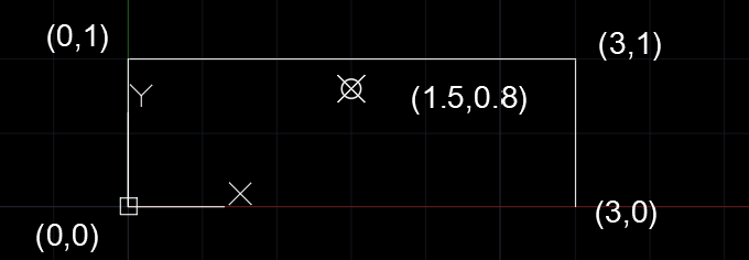
@devitg@Saxlle There seems to be some dissagreement of the definition of the geometric center of a polyline. Should the polyline be considered a linear object or a closed shape? If it's a linear object then the geometric center for an open polyline as shown below is (1.5,0.8) and not (1.5,0.5). There is no line from (3,0) to (0,0) that influeces the location of the geometric cener. My code above considers the polyline as a series of lines and not the bounds of a shape (which is ill defined as it is open). There is also the interpretation of how to handle a polyline that is "open" but should be considered a closed shape where the last vertex is assumed to be the same as the first vertex. In this case the polyline needs to be tested for the "closed" property and then appropriately dealt with to define a closed shape.
-
Perhaps not support LOFTNORMALS yet !!!! Thanks
-

Geometric center of open polyline, line
Saxlle replied to maahee's topic in AutoLISP, Visual LISP & DCL
Okay, this is the sub-function for calculating geometric center for open or closed polygon made from polyline. ; ******************************************************************************************* ; Sub-Function : SX:geomCenter ; Description : Geometric center for open or closed lwpolyline for 2D polygons ; Arguments: : ent - Selected entity into the drawing ; Calling function : (SX:geomCenter ent) ; Author : Saxlle ; Date : August 11, 2025 ; ******************************************************************************************* (defun SX:geomCenter ( ent / ptlist sum_x sum_y sum_area temp_area i len temp_x temp_y j cen_x cen_y cen_pt) (setq ptlist (mapcar 'cdr (vl-remove-if-not (function (lambda (x) (= (car x) 10))) (entget ent)))) ;; point list (if (and (equal (cdr (assoc 0 (entget ent))) "LWPOLYLINE") (>= (length ptlist) 3)) (progn (setq sum_x 0.0 sum_y 0.0 sum_area 0.0 temp_area 0.00 i 0 ) (repeat (setq len (length ptlist)) (if (< (1+ i) len) (progn (setq temp_area (- (* (car (nth i ptlist)) (cadr (nth (1+ i) ptlist))) (* (car (nth (1+ i) ptlist)) (cadr (nth i ptlist)))) sum_area (+ sum_area temp_area) temp_x (+ (car (nth i ptlist)) (car (nth (1+ i) ptlist))) temp_y (+ (cadr (nth i ptlist)) (cadr (nth (1+ i) ptlist))) sum_x (+ sum_x (* temp_x temp_area)) sum_y (+ sum_y (* temp_y temp_area)) i (1+ i) ) ) (progn (setq j 0 temp_area (- (* (car (nth i ptlist)) (cadr (nth j ptlist))) (* (car (nth j ptlist)) (cadr (nth i ptlist)))) sum_area (+ sum_area temp_area) temp_x (+ (car (nth i ptlist)) (car (nth j ptlist))) temp_y (+ (cadr (nth i ptlist)) (cadr (nth j ptlist))) sum_x (+ sum_x (* temp_x temp_area)) sum_y (+ sum_y (* temp_y temp_area)) ) ) ) ) (setq sum_area (/ sum_area 2)) (if (not (equal sum_area 0.0)) (setq cen_x (/ sum_x (* sum_area 6)) cen_y (/ sum_y (* sum_area 6)) cen_pt (list cen_x cen_y) ) ) (prompt (strcat "\nThe geometric center is: " (rtos cen_x 2 2) "," (rtos cen_y 2 2))) (princ) ) (progn (cond ((equal (cdr (assoc 0 (entget ent))) "LWPOLYLINE") (prompt "\nSelected entity is POLYLINE and the number of vertices are lower than 3! Need at least 3 or more vertices!") (princ) ) ((equal (cdr (assoc 0 (entget ent))) "LINE") (prompt "\nSelected entity is LINE and the center is the midpoint!") (princ) ) ) ) ) ) An example video of how it works. geomCenter.mp4 Best regards. -
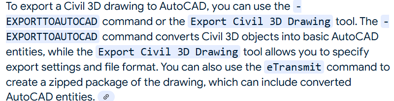
Ok I have the "group by code" for descriptions. So next step is a look up for layer name to match the description. The description look would have like CIV3D description keys. Any way thought I posted try "EXPORTTOAUTOCAD" a CIV3D command to do just that convert CIV3D objects to plain Autocad objects. Here is the file to do what you want, but try export first. @devitg give it a try. spagetti.lsp
-

Extracting data to excel from selected objects on different layers
kidznok replied to Hsanon's topic in AutoLISP, Visual LISP & DCL
Hi, I create dwg and xslx. I add hatch, circle, text, mtext and block. If someone have time and can help with that I will be grateful Date for lisp.dwgDate for lisp.xlsx -
Just tried it, I specified Charset parameter as "unicode" and it worked well, thanks!
-

How to stop flip action reversing offsets in dynamic block
jamami replied to jamami's topic in AutoCAD Drawing Management & Output
I think I am on top of this now, thank you for all you insightful comments . No need for additional code at this stage . -
@devitg the first two characters are already the identifiers, you can use @Lee Mac and Marco Ribar LM-MR:wcmatchx to extract it from the description. @BIGAL This is the reason why I'm trying to build this code library to avoid the export process in Civil 3D if you are doing a quick or small-scale projects since these will all end in a plain AutoCAD Template. By the way here is the complete flow of the process to create blocks and lines based on code description, I just cut the parts of Blocks and Lines Library cause it's too long. List of Line Groups here is simply a point list '(ENZ). That is why I'm trying to find other way to build a list of point groups then process it after all the csv lines are read. (if ; start the csv validation (and (setq fn (getfiled "\n" (getvar 'dwgprefix) "csv;txt;*" 16)) ; get csv file (setq cd (LM:readcsv fn)) ; read csv line thanks to @LeeMac ) ;and (progn (setq grd1 '() grd2 '() grd3 '() grd4 '() grd5 '() grd6 '() grd7 '() grd8 '() ; empty list for 8 simultaneous lines . ; and so on . . ) ;setq (foreach ln cd (if (= (length ln) 5) ; format = '( p e n z d ) (progn (setq ptn (nth 0 ln) ; point number des (nth 4 ln) ; point code plyr "0" ; default point/block layer if not in the code library tlyr "0" ; default annotation layer if not in the code library cs (/ 2.0 (getvar 'cannoscalevalue)) ; scale factor to be used for blocks hgt (/ 1.6 (getvar 'cannoscalevalue)) ; height factor to be used for annotation pt (list (atof (nth 1 ln)) (atof (nth 2 ln)) (atof (nth 3 ln))) ; insertion point ) ;setq (if (= 3 (length pt)) ; format = '( e n z ) to verify if 3D Point (setq pt (trans pt 1 0) ; convert point to ucs pt1 (list (car pt) (+ (cadr pt) (* hgt 0.6 (sqrt 2.5)))) ; text position (single line annotation) pt2 (list (car pt) (+ (cadr pt) (* hgt 0.95 (sqrt 2.5)))) ; text position (double line annotation) val (rtos (caddr pt) 2 2) ; text value based on description (default is elevation) mtp pt1 ; dummy string for annotation position ) ;setq ) ;if (cond ; First condition if Point Blocks ((= "BP" (TG:Read des "BP")) (setq plyr....)) ; If Match the Description set block preperties . ; and so on . . (t ; Else Lines ;;Start of Line List Group (cond ((or ; Set two conditions using LeeMac And Marco LM-MR:wcmatchx function (LM-MR:wcmatchx des "*@#*"....) ; Alpha-Numerical Combo (LM-MR:wcmatchx des "*@@*"....) ; Alphabet Combo ) (if (LM-MR:wcmatchx des "*L1*") ; If Match Description (progn (setq bn "HIDDEN"....) ; Set Block (Line End Points) and Line Propterties (setq grd1 (append (list pt) grd1)) ; Get Points for L1 Group ) ) (if (LM-MR:wcmatchx des "*L2*") ; If Match Description (progn (setq bn "HIDDEN"....) ; Set Block (Line End Points) and Line Propterties (setq grd2 (append (list pt) grd2)) ; Get Points for L2 Group ) ) . ; And so on . . ) (t ;Else if description is not found in the library (setq bn "HIDDEN" bs (* 0.5 cs) plyr "0" val "") ;Default Settings ) ;second T ) ;second cond ) ;first T ) ;first cond ; (if (/= val "") ; Annotation, Blocks and Lines Create if conditions are met (progn (tg:cr8mtx val tlyr hgt mtp) ; Call the function to generate annotations (tg:binsert bn pt bs ptn des plyr) ; Call the function to generate blocks ) (progn (tg:binsert bn pt bs ptn des plyr) ; Call the function to generate blocks (cond ((or ; Settings for Trigger to generate line groups (LM-MR:wcmatchx des "*L#A*") ; If Arc is ended (LM-MR:wcmatchx des "*L#C*") ; If Line is closed (LM-MR:wcmatchx des "*L#E*") ; If Line is ended ) (cond (((LM-MR:wcmatchx des "*L1*")) ; If L1 is called (TG:MKELN grd1 "GARDEN") ; Generate L1 Line List (setq grd1 '()) ; Reset L1 List after lines are generated ) ((=(LM-MR:wcmatchx des "*L2*")) ; If L2 is called (TG:MKELN grd2 "GARDEN") ; Generate L2 Line List (setq grd2 '()) ; Reset L2 List after lines are generated ) . ; And so on... . . ) ; inside cond ) ; GARDEN LINES GROUP ) ; first cond ) ; progn ) ; if val ) ; inside progn ) ; inside main ) ; foreach ln ) ; main progn ) ; main if csv ;; As of the moment (TG:MKELN LIST LAYER) Function is for Line Creation only, Arcs are not yet included since I'm still struggling on how to do it along the Line List Group. ;; What I'm trying to achieved is to create a list of point groups, if "S" or "E" or "A" is present in the code identifiers it will generate a new group of line points in the list. (setq mylist '( ("L1" '(pt1 pt2 p3....pn)) ; if Start or End is called create group ("L1" '(pt1 pt2 p3....pn)) ; if Arc is called create group ("L2" '(pt1 pt2 p3....pn)) ; another group for L2 if Start or End is called ("L1" '(pt1 pt2 p3....pn)) ; then another group for L1 if Start or End is called ) ) ;; Then process the list of lines and arcs after by calling the identifiers and corresponding group of points
-
There is Export to Autocad in CIV3D that should convert lots of stuff.
-

How to stop flip action reversing offsets in dynamic block
BIGAL replied to jamami's topic in AutoCAD Drawing Management & Output
The idea is that you could break down the task to individual blocks and either have the five blocks or a dynamic block that sets the correct truss size visibilty but a say 10m would be 5 individual blocks, much easier to manipulate than have some 50 visibility states. Ok so just read the length match sizes if a size is 0 then don't add it to the draw trusses. I have also thought could save the build order in a different pattern say a 26m would be (26 "2x6" "1x2" "2x6") so the 2m truss would be in the middle. A 10 would be just (10 "2x5") its easy to convert the number of in a repeat. Re angle just insert the blocks and rotate all of them in one go. Yes needs new code which time permitting will do. - Yesterday
-

Geometric center of open polyline, line
devitg replied to maahee's topic in AutoLISP, Visual LISP & DCL
@Mahee , please give it a try , will work both for open and closed lwpolylines it get the Centroid from a temporary Region from a temporary closed polyline if poly is open get-center.LSP get-center.LSP get poly center.dwg -
@GLORY As I can get ,there are same point with same identifier (last text at csv line) Mybe you can add some new identification to group by it at same CSV Like this 1,21.188,19.762,0.000,L1S,pl1.1 4,32.984,30.378,0.000,L1,pl1.2 5,45.117,40.995,0.000,L1,pl1.3 8,57.587,50.937,0.000,L1E,pl1.4 2,31.804,7.629,0.000,L2S,pl2.1 3,44.106,18.077,0.000,L2,pl2.2 6,56.239,26.671,0.000,L2,pl2.3 7,68.878,36.782,0.000,L2E,pl2.4 9,49.168,65.549,0.000,L1S,pl3.1 10,43.612,72.164,0.000,L1,pl3.2 11,50.491,77.059,0.000,L1,pl3.3 12,55.253,70.179,0.000,L1C,pl3.4 13,41.363,59.993,0.000,L2S,pl4.1 14,34.616,68.460,0.000,L2,pl4.2 15,27.472,64.094,0.000,L2,pl4.3 16,33.954,55.495,0.000,L2C,pl4.4 Or state in a new csv which order belong to each polyline Say Line1 and 2 Group List- oredr + idfier.dwg
-
Sorry guys for the late reply. @devitgHere is an example of the drawing processed by the code I've been trying to work on for a while now. But it can only handle 2-Description at a time, either a combination of two different lines or a line and block combo. Let say, “L1E/L2S” or “L1S/BP” which is a point block and can no longer TRIGGER to read 3-Description csv line like “L1E/L2S/BP”, this kind of description can only plot the “BP”, it will not plot the "L1" lines calling “L1E” (the trigger) to plot L1 Group then start collection of L2 point groups. But upon checking the group list say for L1, the points are there inside that list but cannot trigger to plot the L1 group of points into lines since BP is already called in the first condition of the code. This is the reason I want to change the point collection list into groups and process the line list groups after reading all the lines in the csv. @BIGAL, thank you for your response. I also work in Civil 3D to process these kinds of data. The only problem is that you need to export it in plain AutoCAD format to arrange all the annotation etc., cause COGO are not easy to handle. Say aligning the annotation for block points to be aligned to lines or move it into desired location. Line1 and 2 Group List.dwg