All Activity
- Past hour
-
 Meldin joined the community
 -
Hi, I need to check in AutoLISP whether an attached Xref in the current drawing creates a circular reference (refers to itself or a parent Xref). Is there a way, using AutoLISP or ActiveX, to detect this before attaching or reloading the Xref? Ideally, a function that takes the Xref name and returns True/False for circular reference. Any sample code or approach would be greatly appreciated.
- Today
-
 uksafa joined the community
 -

Help Appreciated: Force Existing Layer Names to UPPER CASE Not Working
Saxlle replied to Clint's topic in AutoLISP, Visual LISP & DCL
I found this tool online (screenrec), but I'm not satisfied well. The reason is that I'm the using gifcap, so didn't work properly yesterday when tried to make video, so I find this as alternative. I've forgotten to mention this Multi toggles as alternative, so I agree with that it can be useful. -
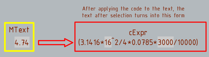
Thanks, the code works with the Texts. I changed the selection line a bit. (setq choice (getkword "\nChoose Percision From:To : [1:2/1:3/2:1/2:3/3:1/3:2]: ")) But nothing works with the MText.
-
Thanks, the code works perfectly with the Texts, I didn't even think it was possible. But nothing works with the MText. I choose the MText, I choose "Precision of target number", but the precision does not change. If the code is applied to the MText, then after that the MText cannot be copied and pasted into another drawing. change_prec_fields.dwg
-
 Eric in CAD HK joined the community
 -

[VLX] SectionSync LITE – Viewport sync along a polyline path (Civil 3D/AutoCAD)
AutoLISP Wizard posted a topic in AutoLISP, Visual LISP & DCL
Hi everyone, I’ve been working on a small production tool in AutoLISP/VLISP for AutoCAD / Civil 3D and thought it might be useful to share here for anyone doing a lot of section or profile sheets. ## What problem it solves On corridor / section jobs we often end up with several paper-space viewports that all need to: - Use the same scale and twist - Stay aligned to a centerline / path (alignment, guide polyline, etc.) - Be re-centered after design changes The usual manual workflow for us was: 1. Set up one “master” viewport with the correct scale, twist, layers, etc. 2. Copy that viewport across the layout for each station/section. 3. Manually PAN/ZOOM/DVIEW in each viewport to center the correct station along the path. 4. Repeat that pan/zoom step any time the design or alignment changed. It works, but it’s tedious and easy to make mistakes when you have a lot of sheets. ## What SectionSync LITE does SectionSync LITE is a compiled VLX that: - Lets you pick a polyline path (e.g. alignment, section chain, etc.) - Associates multiple paper-space viewports with positions along that path - Updates the view center of each viewport so it “follows” the path - Preserves the existing viewport scale and twist - Can be re-run after design changes so you don’t have to manually re-pan everything It was written mainly with Civil 3D section/profile sheets in mind, but it’s just working with standard AutoCAD viewports and a polyline. ## Technical notes - Written in AutoLISP/Visual LISP and compiled to VLX for distribution. - Uses vla/vlax functions to read and set viewport center, width/height, and twist. - Path positions are based on cumulative distance along the selected polyline. - No reactors or custom objects – it just runs on demand and updates existing VPs. ## Demo + download Short demo video: https://youtu.be/l1JRbz4_owQ Download / more details (there’s a built-in 5-run / 7-day trial so you can test it on a real project): https://autolispwizard.gumroad.com/l/civabs If anyone is interested in the implementation details (polyline parameterization, handling UCS and VP twist, etc.) I’m happy to discuss approaches or share pseudo-code for the core parts. -
AutoLISP Wizard joined the community
- Yesterday
-
Using Bricscad dwg has a solid, finds trace. Or do you mean (setq ss (ssget "_X" (list (cons -4 "<NOT") (cons 0 "3DSOLID,TRACE") (cons -4 "NOT>")(cons 410 (getvar 'ctab)))))

-

Help Appreciated: Force Existing Layer Names to UPPER CASE Not Working
BIGAL replied to Clint's topic in AutoLISP, Visual LISP & DCL
Yes should have dbl clicked still hard to see what is in dcl. -
@mhupp this may be useful, it captures command errors so after loading your lisp. You type say p2-3 on command line. Can do say p1-2, Pr3-2, prec1-0 and so on. ; test trap a command used as variable input ; BY Alan H 2019 ; now 2025 ( (lambda nil (vl-load-com) (foreach obj (cdar (vlr-reactors :vlr-command-reactor)) (if (= "fillet-reactor" (vlr-data obj)) (vlr-remove obj) ) ) (vlr-command-reactor "fillet-reactor" '((:vlr-unknowncommand . fillet-reactor-callback))) ) ) (defun fillet-reactor-callback ( obj com ) (setq com (car com)) (alert com) ; do the split com into ; (Change_Prec X X)) ) ; defun (or fillet-reactor-acdoc (setq fillet-reactor-acdoc (vla-get-activedocument (vlax-get-acad-object))) ) Thinking more maybe only check p12, prec10
-
Whether with (ssget "_X" '((0 . "*") (-4 . "<NOT") (0 . "3DSOLID") (-4 . "NOT>"))) or (ssget "_X" (list (cons 0 "~3DSOLID"))), it also dismisses the entities TRACE et SOLID???? I was cheated because my selection being numerous, the grips were not actif.et I could not see the highlighting with filled shapes.
-
Thank you @marko_ribar much simpler. Added look in current Layout or Model. In Civ3D may find surfaces also that are not displayed. (ssget "_X" (list (cons 0 "~3DSOLID")(cons 410 (getvar 'ctab))))
-

Help Appreciated: Force Existing Layer Names to UPPER CASE Not Working
mhupp replied to Clint's topic in AutoLISP, Visual LISP & DCL
Hit the X button bottom Right. -
K updated my code as well. tho this seems to not work well with BricsCAD. moved the vlax-put to only update when the if statment is true. change_prec_fields_update.lsp
-
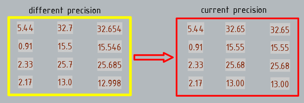
I've modified my latest code to introduce current precision and search in the Mtext
-
Help Appreciated: Force Existing Layer Names to UPPER CASE Not Working
BIGAL replied to Clint's topic in AutoLISP, Visual LISP & DCL
@Saxlle just a comment a bit hard to see what is going on in video maybe use a screen area rather than full screen. Win 11, Shit+Window+R allows screen area record. Drag window area then start / stop. This may be useful rather than a list box can tick one or all choices, add an All option so one click. Examples in code. Multi toggles.lsp -
(ssget "_X" (list (cons 0 "~3DSOLID")))
-
For some reason, the code only works in Text. When selecting MText, the precision does not change... Is it possible to assign the same precision or current precision to fields with different precision?
-
And with this syntax? (sssetfirst nil (ssget "_X" '((0 . "*") (-4 . "<NOT") (0 . "3DSOLID") (-4 . "NOT>"))))
-
With (initget) and (getkword) for choice precision... (vl-load-com) (defun c:change_prec ( / ss AcDoc Space prec_source ktarget n ename Obj value_string nbs tmp_nbs) (princ "\nSelect MText.") (while (null (setq ss (ssget (list '(0 . "*TEXT") (cons 67 (if (eq (getvar "CVPORT") 1) 1 0)) (cons 410 (if (eq (getvar "CVPORT") 1) (getvar "CTAB") "Model")) ) ) ) ) (princ "\nAren't MText or Text!") ) (setq AcDoc (vla-get-ActiveDocument (vlax-get-acad-object)) Space (if (= 1 (getvar "CVPORT")) (vla-get-PaperSpace AcDoc) (vla-get-ModelSpace AcDoc) ) ) (vla-startundomark AcDoc) (initget 1 "0 1 2 3 4 5 6 7 8 9 10 11 12 13 14 15 16 Current") (setq ktarget (getkword "\nPrecision of target number [0/1/2/3/4/5/6/7/8/9/10/11/12/13/14/15/16/Current]?: ")) (repeat (setq n (sslength ss)) (setq ename (ssname ss (setq n (1- n))) Obj (vlax-ename->vla-object ename) ) (setq value_string (vla-FieldCode Obj) nbs 0) (cond ((vl-string-search "%<\\" value_string nbs) (while nbs (if (setq nbs (vl-string-search "%pr" value_string (setq tmp_nbs nbs))) (setq prec_source (itoa (atoi (substr value_string (+ nbs 4) 2))) value_string (vl-string-subst (if (eq ktarget "Current") (strcat "%pr" (itoa (getvar "LUPREC"))) (strcat "%pr" ktarget) ) (strcat "%pr" prec_source) value_string tmp_nbs ) nbs (1+ nbs) ) ) ) (vlax-put Obj 'TextString value_string) ) ) ) (vla-endundomark AcDoc) (prin1) )
-
Help Appreciated: Force Existing Layer Names to UPPER CASE Not Working
mhupp replied to Clint's topic in AutoLISP, Visual LISP & DCL
Could go with a third Middle option. (setq layname (ApplyCASE "LAYERNAME")) LaYeRnAmE .... (defun ApplyCaSe (s / i n ch out) (setq n (strlen s) i 1 out "") (while (<= i n) (setq ch (substr s i 1)) (setq out (strcat out (if (= (rem i 2) 0) (strcase ch T) (strcase ch) ) ) ) (setq i (1+ i)) ) out ) -Edit or a more realistic Option Only first letter UpperCase (setq layname (ApplyCASE "LAYERNAME")) Layername (defun ApplyCase (s / i n ch out) (setq n (strlen s) i 2 out (strcase (substr s 1 1) T)) (while (<= i n) (setq ch (substr s i 1)) (setq out (strcat out (strcase ch)))) (setq i (1+ i)) ) out ) -
I'll have to debug it when i get home just typed it up in note pad. -Edit Well if i took two seconds to look at the code. was using integers and needs to be strings. because Tusky is calling vl-string-subst. if its still bugged ill fix it tonight.
-
Thanks, that's a good idea, but this code doesn't work for me.
-
Added a little on the front end to wrap it all in one command with user input options. Should display something like this Change_Prec or CP Enter "C" for Custom Values Choose Percision From:To : [1:2 1:3 2:1 2:3 3:1 3:2]: 3:2 Changing Select MText Precision From [3] to [2] ... Change_Prec or CP Enter "C" for Custom Values Choose Percision From:To : [1:2 1:3 2:1 2:3 3:1 3:2]: C Existing Precision: 1 Precision Change to: 4 Changing Select MText Precision From [1] to [4] ... Change_Prec 2 1 Changing Select MText Precision From [2] to [1] ... -Edit Updated it so you can just type "Change_Prec 3 2" and skip all that and just start asking you to make a selection.
-
I already tried it, but something strange happens: it filters the 3D solids, but it puts the other elements at z=1.0000E+99
-
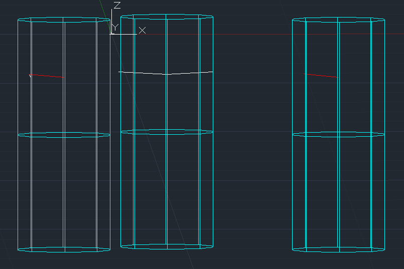
 I’m working on an AutoCAD .NET (C#) command that creates two Solid3d cylinders (one in +Z and one in –Z direction) starting from a selected point on an insulator line. Each cylinder is created with CreateFrustum, then moved into place using TransformBy(Matrix3d.Displacement) and optionally rotated around the point. However, I’ve run into a strange issue: sometimes the cylinders appear exactly in the correct place, but sometimes they shift several meters away from the point. In some cases both cylinders stack on each other, even though they should be separated along the Z-axis. The LIST command occasionally shows bounding boxes like: X = [-3500, 3500] Y = [-3500, 3500] Z = [-5000, 5000] which means the cylinder was never displaced at all, even though I definitely applied the transform. Here is the code that draws the cylinders: private void DrawClearanceCylinders(Database db, Editor ed, IEnumerable<Point3d> centers, double radius, double angleDeg) { if (centers == null) return; double h = CYL_LENGTH; double angRad = angleDeg * Math.PI / 180.0; using (var tr = db.TransactionManager.StartTransaction()) { var bt = (BlockTable)tr.GetObject(db.BlockTableId, OpenMode.ForRead); var btr = (BlockTableRecord)tr.GetObject( bt[BlockTableRecord.ModelSpace], OpenMode.ForWrite); foreach (var c in centers) { Solid3d cylUp = new Solid3d(); cylUp.SetDatabaseDefaults(); cylUp.CreateFrustum(h, radius, radius, radius); cylUp.TransformBy(Matrix3d.Displacement( new Vector3d(c.X, c.Y, c.Z))); if (Math.Abs(angleDeg) > 1e-6) cylUp.TransformBy(Matrix3d.Rotation(angRad, Vector3d.XAxis, c)); btr.AppendEntity(cylUp); tr.AddNewlyCreatedDBObject(cylUp, true); Solid3d cylDown = new Solid3d(); cylDown.SetDatabaseDefaults(); cylDown.CreateFrustum(h, radius, radius, radius); cylDown.TransformBy(Matrix3d.Displacement( new Vector3d(c.X, c.Y, c.Z - h))); if (Math.Abs(angleDeg) > 1e-6) cylDown.TransformBy(Matrix3d.Rotation(angRad, Vector3d.XAxis, c)); btr.AppendEntity(cylDown); tr.AddNewlyCreatedDBObject(cylDown, true); } tr.Commit(); } } The logic seems correct: create → displace → rotate → add to model space. But the result is inconsistent, and sometimes the displacement appears to be ignored. I’m trying to understand whether: CreateFrustum has an internal origin/transform I’m not accounting for the rotation around point c is interfering with the placement Solid3d requires a different transform order or if there’s a known issue with Solid3d placement after creation If anyone has experience with placing Solid3d cylinders precisely at a specific point, or knows what could cause the transforms to behave inconsistently, I’d really appreciate your insight. Command: LIST 6 found 3DSOLID Layer: "clerance_zone" Space: Model space Color: 4 (cyan) Linetype: "CONTINUOUS" Handle = 1000070 History = None Show History = No Bounding Box: Lower Bound X = 16294.5100, Y = 28025.7321, Z = -20484.5100 Upper Bound X = 24294.5100, Y = 36025.7321, Z = -10484.5100 3DSOLID Layer: "clerance_zone" Space: Model space Color: 4 (cyan) Linetype: "CONTINUOUS" Handle = 100006f History = None Show History = No Bounding Box: Lower Bound X = 16294.5100, Y = 28025.7321, Z = -10484.5100 Upper Bound X = 24294.5100, Y = 36025.7321, Z = -484.5100 3DSOLID Layer: "clerance_zone" Space: Model space Press ENTER to continue: Color: 4 (cyan) Linetype: "CONTINUOUS" Handle = 100006e History = None Show History = No Bounding Box: Lower Bound X = 1484.5100, Y = 32991.0000, Z = -20484.5100 Upper Bound X = 9484.5100, Y = 40991.0000, Z = -10484.5100 3DSOLID Layer: "clerance_zone" Space: Model space Color: 4 (cyan) Linetype: "CONTINUOUS" Handle = 100006d History = None Show History = No Bounding Box: Lower Bound X = 1484.5100, Y = 32991.0000, Z = -10484.5100 Upper Bound X = 9484.5100, Y = 40991.0000, Z = -484.5100 3DSOLID Layer: "clerance_zone" Space: Model space Color: 4 (cyan) Linetype: "CONTINUOUS" Handle = 100006c History = None Show History = No Thanks!
-

Help with 3D spur gear drawing (no tooth width given) !!
CyberAngel replied to Nlevismith95's topic in AutoCAD 3D Modelling & Rendering
Unfortunately, a lot of courses try to teach you to read plans as well as draw them. The information seems to be there, but you have to puzzle it out. One element of the tooth has two points of tangency and a radius. Once you draw that arc, you have the point of intersection with the outside radius. The outer width of the tooth is almost irrelevant to the design, because it's the last piece. The most important dimension seems to be the pitch, because that's where the teeth meet. Mechanical isn't really my field, so someone else will probably be able to give you better information.