Leaderboard


Popular Content
Showing content with the highest reputation on 12/12/2025 in Posts
-
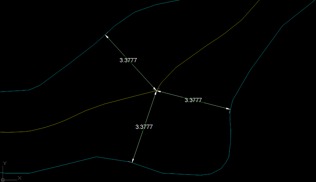
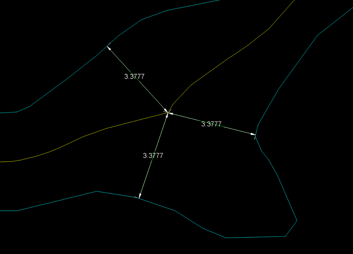
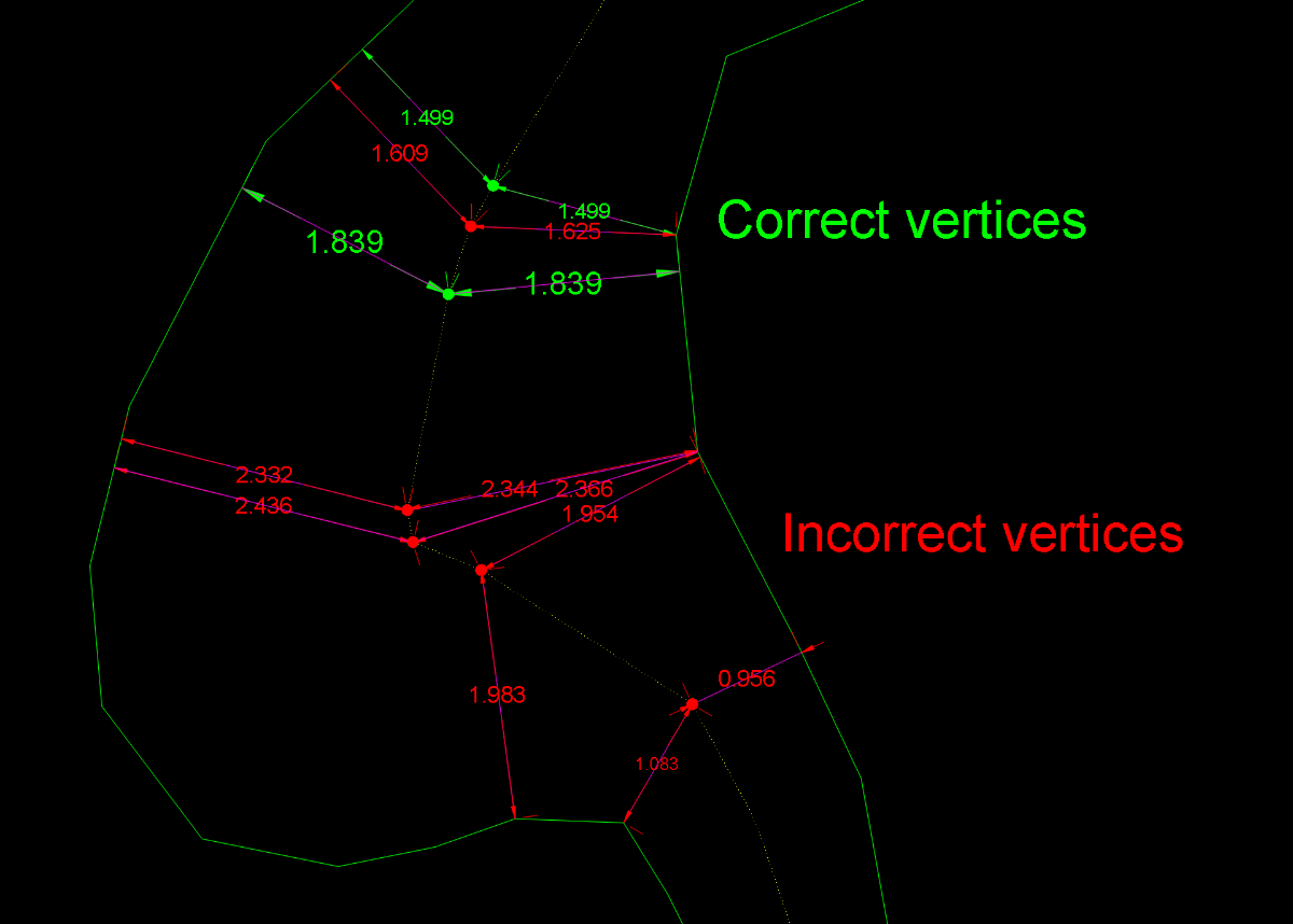
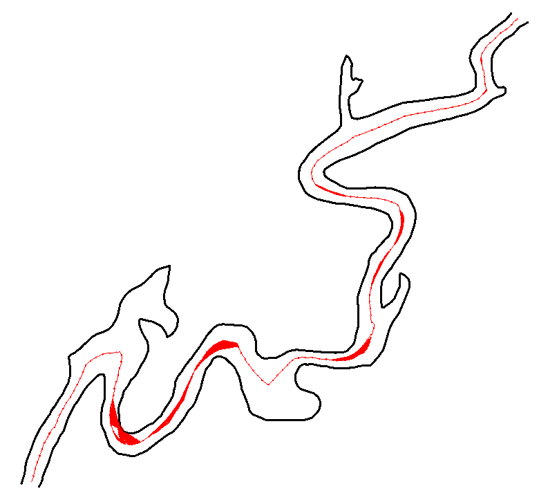
Obviously, this has now become something more than just the search for a solution to a single user’s problem. First of all, I should say that I myself was also reluctant to accept the concept of equidistance advocated by @GP_ and @dexus For the simple reason that applying this principle forced me to accept that the centerline should be the same in these two drawings. Equidistance requires ignoring those areas of the margins that do not geometrically affect the axis. This, which initially caused me some resistance, I eventually came to accept conceptually when I realized that it could serve as a criterion for defining what is a “recodo/inlet” and what is not. So I have abandoned my previous approach and adapted it to this new situation. Having made this clarification, I must say that this concept of equidistance makes the calculation of a centerline more feasible. I’ve been running some tests with Dexus’s latest code, which is the best so far. However, I’ve discovered some “holes” that I hadn’t noticed before. I’m attaching a few images showing this. In my view, these are conceptual errors rather than geometric limitations. And what can we consider “geometric limitations”? I believe that, in any case, every vertex of the centerline must be equidistant from both margins. If this is not the case, the result is not correct. However, the intermediate regions along each segment may be subject to geometric limitations depending on the desired precision. Therefore, in bends or turns, the points taken within the adjustment or “problematic” segments may deviate (within a tolerance) from strict equidistance. The goal, therefore (in my opinion), should be to achieve equidistance at every vertex and to remain within a tolerance in the intermediate zone of each segment. After everything written here so far, some might wonder: is it really possible to obtain a centerline that meets these requirements? As far as I’m concerned, I’m running some tests. GusanoAcad.mp4 I’ll post something over the weekend
 2 points
 -
See on archive of the web: UNMI.LSP2 points
-
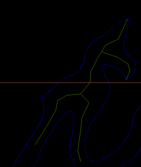
I think with those big side offshoots you need to break the river into multiple plines so you would have two or more centrelines lines in that situation. As suggested by @SLW210 The problem will be how to work out the break offset shape.. Ps image dummied up.
1 point
-
IIRC, those are tough to manage on GIS programs with Add-ons made with Python, .NET, etc. Remember, real rivers/roads/ROWs have curves and organic shapes, not just straight lines. I did see some information on how to tackle those, hopefully it can be worked out, but don't expect perfection. As I mentioned, from what my daughter said and what I've seen in various related forums, the GIS pros are using whatever program and add-ons they can to get the bulk of it and cleaning up and filling in manually. Most that are doing those shapes want the main channel center, if needed I would ignore the very wide sections and side pieces and get those as center lines running back to the main channel separately. As your example shows, it would take separate polylines, so it will need to account for those sections and then ran again on the offshoots. You still haven't answered all of the questions asked. What type of work are you doing? What you have posted looks to be Civil and/or GIS work. I'll try some more on this when I can, I have also looked at some different shortest path codes, the last example is way over my head in LISP, I'll concentrate on the previous examples then try to run just the main channel on the last example .dwg. I have a full slate at work again today, but I'll try to jump back on this when I get some things out of the way. Home time is limited, but I'll try to get back on this with QGIS solution, I may see if my daughter's coworkers want to take a shot at these.1 point
-
Hi @PGia, wow, you managed to find another example that fails. Good stress testing! The reason mine fails is because it ignores the offset lines that are split in two or more parts. But some of the parts are still be usable and should be used. I looked into fixing this and managed to add those lines, but this resulted in some other problems so I didn't update the code on the earlier post yet. The zigzag problem is coming back on your example. The result below. I really need to find a solution for that, but it looks like I might have to use a path finding algorithm which would slow down the code a lot. Sorting the points by distance on the offset line is not enough anymore.
1 point