Search the Community
Showing results for tags 'bolts'.
Found 3 results
-
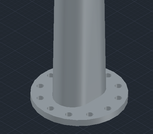
I am trying to show the bolt holes in flanges. I would like to know if this is just a setting that must be turned on in AutoCAD or if I need to make the bolt holes myself. If I need to make them myself, can I edit an existing flange or do I need to make it from scratch for every size? If it is just a setting where can I find it? Thank you!
-
I found the attached LISP routine on my company's network. It draws a side view of a hex head bolt. It works pretty well although it does pop up a few errors at the end of the command. I would like to be able to use the command without errors and would like to make a couple modifications to it but I do not know much about LISP. The command draws the bolt as expected but after entering the orientation angle it does this: Enter orientation angle : Unknown command "2DBOLT". Press F1 for help. Pick insert point: Unknown command "2DBOLT". Press F1 for help. Unknown command "2DBOLT". Press F1 for help. Unknown command "2DBOLT". Press F1 for help. Unknown command "2DBOLT". Press F1 for help. Unknown command "2DBOLT". Press F1 for help. Then it draws the bolt correctly. Any ideas why? Also... Currently you have to manually enter a distance for the grip (gap) between the bolt head and nut/washer, I would like to be able to pick the insertion point of the bolt and the insertion point of the nut and use these values to draw the bolt rather than manually entering the grip (gap) distance and rotation angle. Hopefully this all makes sense... I am using AutoCAD 2013. Thanks! 2DBolt.lsp
-
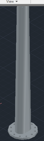
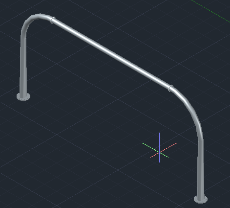
If anyone Here have a Library of Standard Bolts, Nuts and washers ... I need it to fix in a Flange and base plate as shown in this attachments ...