All Activity
- Past hour
-

Automatically placing borehole tables with leaders without overlap
SLW210 replied to MSHR's topic in AutoLISP, Visual LISP & DCL
@PGia is not the OP. The OP is @MSHR. - Today
-

A CODE FOR DIVIDING OBJECTS WITH POINTS AS IN MEASURE AND DIVIDE COMMAND IN AUTOCAD BUT WAY MORE ADVANCED
darshjalal replied to darshjalal's topic in AutoLISP, Visual LISP & DCL
Your name of course will be there always. You too free to use any code I am posting here or modify it for the better ideas. Thank you so much. Regards. -
A CODE FOR DIVIDING OBJECTS WITH POINTS AS IN MEASURE AND DIVIDE COMMAND IN AUTOCAD BUT WAY MORE ADVANCED
darshjalal replied to darshjalal's topic in AutoLISP, Visual LISP & DCL
divcurve-lisp-all-option.mp4 -
 karl22 joined the community
 -
The issue of zoom in Acad and a lisp has been known since I think Acad existed, I know at times have had to use ZOOM C scale to get lisps to work, There may be a way around the problem perhaps using Boundingbox but I certainly have not tested.
-
Idk about that this is a super simple lisp that will allow you to select multiple entites. But if they aren't within the fuzz distance of each other they wont connect. ;;----------------------------------------------------------------------------;; ;; Copy Boundary Entities to join as a single polyline fuzz is 0.1 units ;; https://www.cadtutor.net/forum/topic/99146-boundary-command/ mhupp:06/04/26 (defun C:CBoundray (/ ss ss1 obj) (setq ss1 (ssadd)) (while (setq ss (ssget '((-4 . "<OR") (0 . "LINE") (0 . "ARC") (0 . "LWPOLYLINE") (-4 . "OR>")))) (foreach obj (mapcar 'vlax-ename->vla-object (vl-remove-if 'listp (mapcar 'cadr (ssnamex ss)))) (vla-copy obj) ) (command "_.PEDIT" "_M" ss "" "_J" "0.1" "W" "0" "") ) (princ) )
- Yesterday
-
I had no idea about this issue. Many thanks to everyone for the information It really seems that this is AutoCAD’s ancient problem — known since the end of the previous millennium and still unresolved in this one. In any case, it doesn’t seem to be something easily approachable for Lisp programmers, since it is not easy to find published code aimed at solving this AutoCAD deficiency.
-

Automatically placing borehole tables with leaders without overlap
BIGAL replied to MSHR's topic in AutoLISP, Visual LISP & DCL
@PGia its your turn now people waiting for sample dwg, there are prepared to help, like @CyberAngel I suggested can select boreholes and make a single table of those selected. Repeat as required. -
A CODE FOR DIVIDING OBJECTS WITH POINTS AS IN MEASURE AND DIVIDE COMMAND IN AUTOCAD BUT WAY MORE ADVANCED
BIGAL replied to darshjalal's topic in AutoLISP, Visual LISP & DCL
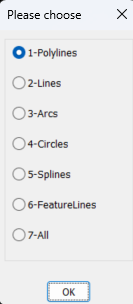
If your offering something a good idea is to provide images or a movie about what the program does, else the "Why bother" will occur. "(setq oldDynPrompt (getvar "DYNPROMPT")) Fails in Bricscad V25. Here is a freebie for you I dont uses initget. Multi radio buttons.lsp (if (not AH:Butts)(load "Multi radio buttons.lsp")) (setq ans (ah:butts but "V" '("Please choose" "1-Polylines" "2-Lines" "3-Arcs" "4-Circles" "5-Splines" "6-FeatureLines" "7-All"))) You ask for a distance only so it would make sense that it ask for intervals, we did road design and in an intersection kerb the curve was nearly always based on 4 points. maybe when asked for a distance enter a -ve value say -4 means break into 4 even spacing. Have added a couple of other make dcl on the fly for you just leave my name in the code but free to use. You can make a dcl then convert it to lsp code using write-line for the dcl code so dont need the MULTI's.Multi GETVALS.lspMulti toggles.lsp
-
 Brady joined the community
 -
It's supposed to use the HPGAPTOL as far as I know. This has been an issue for sometime, now that I looked back into from a few years ago, this problem also occurs with Hatch command. I just tried Boundary and Hatch on a closed polyline object at Zoom Extents and got ... And despite the first instruction, Zooming In resolved the issue. I normally resolve this with Hatch by using Select Object, maybe Hatch, Select Object, delete the Hatch and keep the Boundary could work for the OP. @lastknownuser's post brought it back to my memory. There is a thread around from a while back on this issue and needing to use Select Object option for Hatch.
-

Automatically placing borehole tables with leaders without overlap
CyberAngel replied to MSHR's topic in AutoLISP, Visual LISP & DCL
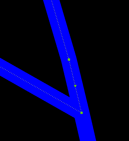
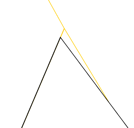
Off the top of my head, could you use polar coordinates to split the site into slices? With 60-degree increments, you have six slices. When you process a borehole, you use the distance from the center of the site to place the table at a proportional distance in the outer area. By setting the placement angle to a clamped fraction of the slice, you get a fixed number of places for the tables, so there's no chance of overlap. That way you don't have a lot of edge cases, and the tables correspond roughly to the boreholes. I'm probably not explaining this clearly. I can put together a diagram and maybe some code if you need them. -

A CODE FOR DIVIDING OBJECTS WITH POINTS AS IN MEASURE AND DIVIDE COMMAND IN AUTOCAD BUT WAY MORE ADVANCED
pkenewell replied to darshjalal's topic in AutoLISP, Visual LISP & DCL
@darshjalal OK - so you updated the first post - with the comments that could already be read in the file. What I asked for was: 1) what it is used for? 2) how it is useful? 3) how the features are helpful? That's all we were asking, rather than the extremely technical description. -
 jjrozo joined the community
 -
Was reading up on this too. apparently AutoCAD boundary command doesn't have a tolerance setting but BricsCAD does. That is why people opt to use hatching and then you can create the boundary from the hatch. and then delete the hatch. I'm confused since their isn't a gap/vertex at that location.
-
The only "solution" besides zooming in I could determine, was to copy the polylines in place and use region on them, which seems to be correct in the example drawing. That should be able to be done with a LISP? Boundary.dwg
-
 111111 joined the community
 -
 latifa joined the community
 -
 Sumon joined the community
 -
Hi All I have changed this code to have more options, you can select ByLayer = Layer 0 + ByLayer color ByBlock = Layer 0 + ByBlock color") KeepAllLayers = Keep original layers and colors") you can also select a block or select everything hope someone finds it useful Burst Nested Blocks.lsp
- Last week
-
TurboPlot v1.1: Standalone, Multi-threaded Batch Plotter (Auto-detects Frames!)
BIGAL replied to vudungcom's topic in Application Beta Testing
A lot of us here are using Bricscad so the Acad Accoreconsole is not usable, have you looked at something similar for Bricscad ? Plus others using Gwstar and Intellicad to mention a couple more. -
Yes, 2000i fails when zoomed out as well.
-
 adfglksjdf joined the community
 -
There was a post a couple of years ago now, if it is a closed shape without crossing lines, hatching the area then recreate the boundary and delete the hatch leaves the boundary... as a last resort since it is long winded way to go. I haven't had time this week to look at this properly - you're in safe hands with the other posters though... (The post I am thinking about was using LISP to do something, click in the area to get boundary, might have been to measure area, perimeter or something but that was the idea behind it, LISP is ok if it is a bit long winded, fractions of a second longer process)
-
 agatanktn joined the community
 -

TurboPlot v1.1: Standalone, Multi-threaded Batch Plotter (Auto-detects Frames!)
vudungcom posted a topic in Application Beta Testing
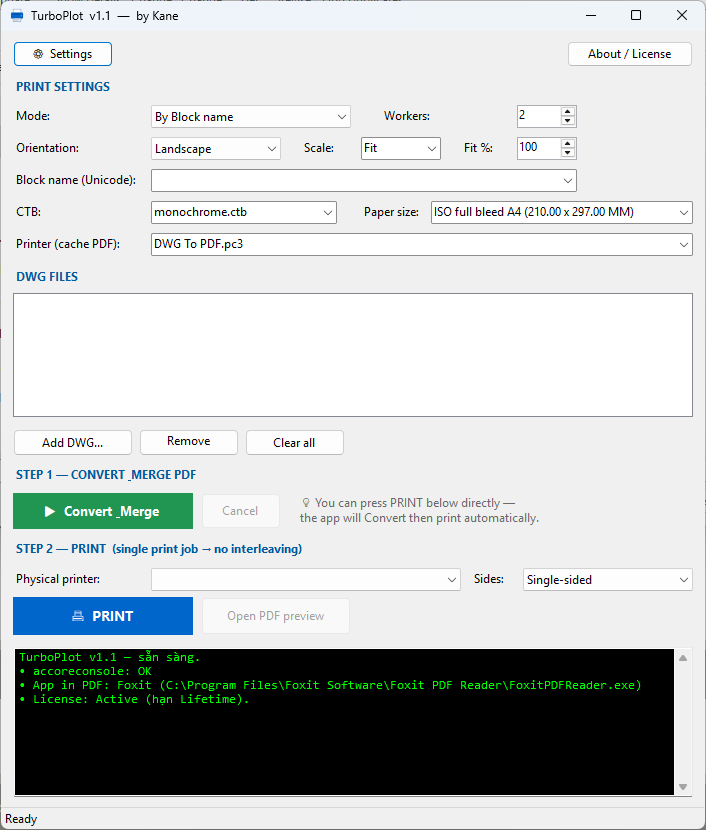
Hi everyone, If you are dealing with hundreds of DWG files daily, you probably know the pain of traditional batch plotting tools: AutoCAD freezes up, memory leaks cause crashes, and worst of all—because it plots so slowly, other people's print jobs often get mixed into your batch on the shared office printer! I’ve developed a standalone software called TurboPlot (v1.1) to solve this exact nightmare, especially when you are on a tight deadline and need your drawings printed instantly. Unlike standard LISP or .NET add-ins that use the slow ActiveX/COM interface, TurboPlot runs completely independently outside of AutoCAD. It utilizes a highly optimized background engine with True Multi-threading, meaning it plots your drawings silently at blazing speeds while you continue working on other things. See it in action: I've recorded a short video demonstrating how it works. Check it out here: [Insert your YouTube Link here] Key Features & Problem Solvers: No More Interleaved Print Jobs: TurboPlot compiles all your drawings into one single merged PDF before sending it to your physical printer as ONE continuous print job. Your batch stays perfectly together—nobody else in the office can interrupt your print queue again! Built for Rush Jobs (True Multi-threading): When you need drawings urgently, you can't afford to watch AutoCAD slowly open and close each file. TurboPlot plots 4, 8, or 16 DWGs simultaneously in the background. It gets the job done in a fraction of the time with zero freezing. Smart Frame Auto-Detection (Game Changer!): You don't need to specify a block name anymore! Leave the name field blank, and TurboPlot will automatically scan the Model or Layout, calculate areas, and instantly find the Largest Frames (whether they are Blocks or closed Polylines) to plot. Multiple Plot Modes: By Block Name: Type your title block name(s) (supports multiple names separated by commas) with a history dropdown. By Layout: Auto-detects and plots all frames within your layouts. Model Extents. PDF Management: Automatically merges hundreds of plots into a single neat PDF, OR saves them as individual PDFs next to the original DWG (with _001, _002 suffixes). No NETLOAD Required: It’s a standalone Windows App. Just open it, drag and drop your DWGs, choose your CTB/Paper Size, and hit run. Multilingual UI: English, Spanish, Portuguese, Chinese, Japanese, Korean, and Vietnamese. Why is it faster & more stable? Because it processes your files in the background without loading the heavy AutoCAD GUI, Ribbons, or Workspaces. It silently grabs the exact Bounding Boxes of your frames and plots them flawlessly (with built-in edge-protection margins so your borders never get cut off). If you are interested in testing it out or saving hours of plotting time every week, let me know or drop a comment below! I'd love to hear feedback from the community. https://www.youtube.com/watch?v=O-ZZ53UuKFQ Download link https://drive.google.com/file/d/14Cn911glapa3nTSigD1srU7LKOHjarz5/view
-
Pretty positive I was zoomed out with the 2000i as well, but I'll retest zoomed out, maybe tonight if home time allows.
-
So I tried zoomed in on AutoCAD 2026 and looks to be correct. Boundary.dwg
-
This has been talked before if I understood the problem correctly: https://www.cadtutor.net/forum/topic/61468-boundary-precision/ To create a boundary you have to have the whole area visible in your model, everything needs to be visible in display area So it has to do something with your "viewing resolution" (zoom), that's how command works. What is the limit I don't know, I never did tests like they did in topic mentioned above. But I also had the same problems with large areas like you posted, when I have one short line, or polyline segment, one of the boundary vertices would be wrong (bad precision). The solution for me was to create lisp working with regions, then convert region to polyline. When creating regions you don't need to see the whole area on your screen, you select the lines and its just pure math from there
-
I use windows terminal winget upgrade. the publisher has to send them the file i think how it works.
-
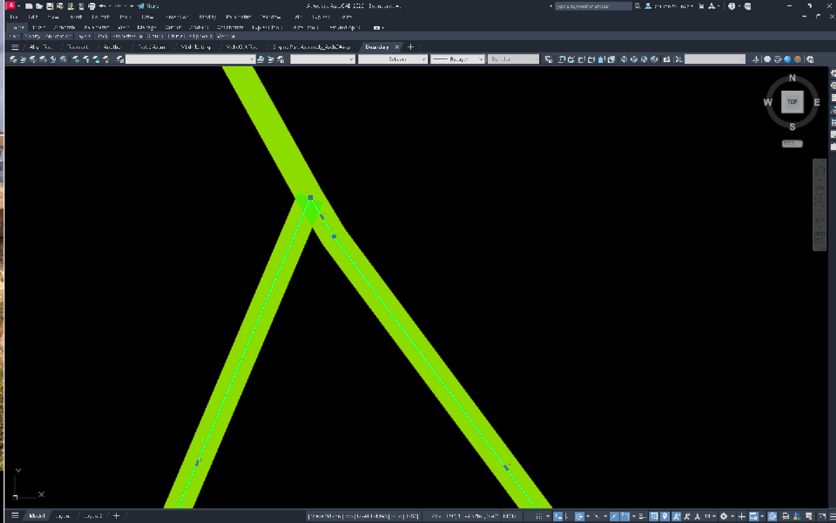
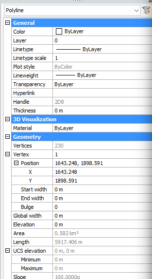
BricsCAD is showing 230 61+119+53 - 3overlapping points.
-
I reversed all the polylines see if that does anything. -Edit Might fix it on the bottom but then mess it up on the top. Rervers Boundary.dwg
-
I exploded the polylines into lines. I also reduced the lineweight to 0, but in both cases the result remains the same. A colleague who still has an old PC with Autodesk Map 5 (= AutoCAD 2002) also confirmed that the same error occurs. If I’m not mistaken, AutoCAD 2002 is basically the same as AutoCAD 2000, so @SLW210’s statement that the "boundary" command works correctly in that version intrigues me.