All Activity
- Past hour
-

Why do hatches become difficult to manage in complex drawings?
SLW210 replied to indiancad's topic in AutoCAD 2D Drafting, Object Properties & Interface
A lot of times if you use the object option it does better. When I get back to work, I'll see how many old threads are around on hatch and boundary issues. - Today
-

Why do hatches become difficult to manage in complex drawings?
Paul Li replied to indiancad's topic in AutoCAD 2D Drafting, Object Properties & Interface
Some times with very odd shaped boundaries AutoCAD just has a hard time filling it with any hatch pattern. That's when I would break the single hatch area up into different area sections. The boundary would be drawn using a PLINE and placed onto a non-plot layer. This usually resolves the issue. Another solution that worked for me involves odd shaped boundaries that are symmetrical. The hatch area when broken up in half hatches perfectly on the left side but refuse to hatch properly on the right. So I would just create the hatch pattern on the side that works and then mirrored that to the other side. -
Why do hatches become difficult to manage in complex drawings?
SLW210 replied to indiancad's topic in AutoCAD 2D Drafting, Object Properties & Interface
AutoCAD is terrible at hatching in several ways, that at least usually is reported by BricsCAD users to do better with the same shape(s). Several threads here and other forums of quirks for this and that on hatching. On another forum, someone posted a spline shape that didn't hatch correctly, though I was able to "FIX" it by offsetting it (with delete option) and then offset it back where it was also with delete option), it also worked fine originally with several hatch patterns and failed on a few others, it also had no issues in BricsCAD reportedly. Sometimes zooming in or zooming out and/or moving closer to 0,0,0 works. Sometimes just using a slightly different pattern works better. I mostly use Solid, Gradient, Steel, Aluminum, et. al. made of straight lines and usually they work better in most instances, seldom do I need Earth, Gravel, Sand, etc. which seems to be the type to have issues. -
It would still be needing manual tweaking or if by LISP still more coding. As I mentioned above I fixed the sizing portion of the original LISP for lines, I will post that version if getting CENTERMARKS automatically placed is too much for me. I think I actually made one once, it's not a bad idea for most and probably, better than the old manual method. I just never understood why you would have a center crosshair or mark or whatever and it not allow associativity. That's the place where you would dimension a feature with a radius. P.S. for @BIGAL and other Aussies, my grandkids are headed back to the States, leaving today getting back Wednesday evening Eastern USA Time. They had a lot of fun and enjoyed Australia, at least what they saw of it. I may have to head over sometime.
-
Yes, I already mentioned that. Easy enough to place them manually, but replacing the dimrad/dimdia marks are not as easy as I was hoping, or I am going about it wrong. I set the Layer I create Centermark to Bylayer and the CENTERMARK layer on that with CENTERLTYPE to ByLayer and that issue is fixed. CENTERLTYPEFILE, I think I have a way to detect Metric and change that to acadiso.lin, so that's solved. I have to get it to find the object, since CENTERMARK works by getting the Circle or Arc object. I am thinking about just turning off the Dimrad/Dimdia Mark/Line and placing a CENTERMARK on all circles and arcs in current space or entire drawing, though that would have concentric objects with more than one, so I have to still sort for the largest for correct size. I have the original using lines working better and properly sizing automatically now, but still tweaking, I am leaving the crosshair lines option for older AutoCAD and CAD's that don't have CENTERMARK option.
-
Using Arraypath function via scripting, duplicating lines are created in opposite direction of curve path
SLW210 replied to harshil's topic in AutoCAD LT
Please use Code Tags when posting code. (use <> in the Editor) Do you have a drawing with a before and after? -
@SLW210 Note - There are several system variables (saved in the drawing) you can change to make the CENTERMARK command behave the way you want: CENTERLAYER = Default Layer CENTERLTYPE = Default LT (can be set to CONTINUOUS) CENTERLTSCALE = Centermark LT Scale CENTERLTYPEFILE = Center LT File used (like acad.lin) CENTERMARKEXE = Centermark Extensions ON/OFF CENTERCROSSGAP = Centermark Cross Gap value (can be relative or hard number) CENTERCROSSSIZE = Centermark Cross Size (can be relative or hard number) CENTEREXE = Centermark Extension Distance
-

Why do hatches become difficult to manage in complex drawings?
CyberAngel replied to indiancad's topic in AutoCAD 2D Drafting, Object Properties & Interface
When I run into a situation like this, the complexity or the effort can become too much, especially if there's a deadline. In that case I'll draw a polyline along the border and use that as the boundary for the hatch. Of course the polyline goes on a nonplotting layer. -

Fun With AutoCAD Grip Options for Arrays: Tuesday Tips With Frank
The AutoCAD Blog posted a topic in AutoCAD Blogs
I’ve said it here before: I never know where I’ll get the inspiration for a Tuesday Tip. This time it came from an old friend and colleague thanks to an interesting LinkedIn post. It demonstrated an alternate method for creating arrays, without using the actual array command. Intrigued yet? Asking why you would do such a thing? As you are aware, there are a lot of controls to create a modern array. Maybe whatever you’re doing doesn’t really require all of those features. It kind of reminds me of a Lambda function in AutoLISP programming, which is an unnamed function that most manuals describe as being used “when the programmer doesn’t need to go to the overhead of creating a full function.” Heh, that’s always stuck with me for some reason. So while you may not use these two methods often, it is kind of fun, and it helps to drive home a couple of points, so let’s get started. Creating a Linear Array With AutoCAD Grips For my two examples, I’ll be using the chair block as found in the Floor Plan Sample drawing. The workflow is pretty simple, and illustrated in the animation below. First, select the block to display its insertion point grip. Select the grip to make it “hot”. Now, recall that hot grips always start with the Stretch command. I’ll click on Copy in the Command Line, and with Ortho on, I’ll pull to the right and specify 1 unit for the grip copy. Here’s a really cool keyboard trick. I press the Control key, and my 1 unit spacing will lock into place, and I can continue clicking to the right to complete my linear array. Creating a Polar Array with AutoCAD Grips Let’s use a similar method to create a polar array. This time, we’ll imagine using our chair block to surround a table with eight equally spaced chairs. I’ll start in the same manner, selecting the block, then selecting its grip. Since I want the chair “array” to go around the table, I’ll type in B to activate the Base Point option, then select the center of the circle using a Center Object Snap. Once that is defined, I want the Rotate option of the grip, so I press Enter to cycle through the available options, stopping when the Rotate option is current. Now, we want to copy our chair, but do it multiple times, so I’ll enter C (copy option) into the Command Line. You’ll see the prompt change from ** ROTATE ** to ** ROTATE (multiple) ** I’ll enter my rotation angle of 45, and the second chair will appear. Now, I’ll again use that handy Control key trick to lock in the rotations, and continue to place the remaining blocks. Granted, these alternate arrays (I think I’ll call them Lambda Arrays going forward) don’t have the cool dynamic functionality of a real array object. “But Frank”, you might also be saying, “my real arrays act as a single object, so it’s easier to copy or move them. These are all individual objects.” I’ve got you covered there too. Just use an unnamed group to turn them into a single, selectable object. Click on the big Group icon in the Groups panel of the ribbon’s Home tab. Select your objects and press Enter. If you decide later that you don’t want them grouped anymore, just click the icon in the panel’s upper right corner, and select any item in the group. A Suitable Ending While these methods may or may not be useful to you, they helped me to show some important concepts. One was to remember to use the options available with Grip editing. Access them via the Command Line, cycle through them with the Enter key, or if you have Dynamic Input turned on, use the arrow down button to see your options. While Stretch is the default for all object types, your other options can differ, so remember to check them out. You should know by now that I’m a big fan of keyboard shortcuts. Don’t forget about using the Control key as described here. Prior to the inspiration that drove this post, I was not aware of it. The final point is this. If you’re just getting started, training from an experienced professional can make a real difference. The author of the original referenced LinkedIn post was none other than one of the most well-known CAD trainers out there. You’ve probably heard of him; his name is Michael Beall. Michael is known as The CAD Trainer Guy, and he’s trained thousands of people over the years on AutoCAD, and chances are, he may have even trained you. Thank you for your continued inspiration, Michael! More Tuesday Tips Check out our whole Tuesday Tips series for ideas on how to make AutoCAD work for you. The post Fun With AutoCAD Grip Options for Arrays: Tuesday Tips With Frank appeared first on AutoCAD Blog. View the full article -

Using Arraypath function via scripting, duplicating lines are created in opposite direction of curve path
harshil replied to harshil's topic in AutoCAD LT

-
harshil joined the community
-
(defun c:AUTOHPA ( / objLayer pathLayer objSS pathSS objToArray pathCurve pathLength ) (setvar "CMDECHO" 0) ;; Define your custom layer names here (setq objLayer "V1") ; <-- Replace with your object layer name (setq pathLayer "P1") ; <-- Replace with your path layer name ;; Number of items (setq items 10) ;; Automatically select everything on the object layer (setq objSS (ssget "_X" (list '(0 . "*") (cons 8 objLayer)))) ;; Automatically select the first/only object on the path layer (setq pathSS (ssget "_X" (list '(0 . "*") (cons 8 pathLayer)))) (princ "working01") ;; Check if both selections actually found objects (if (and objSS pathSS) (progn ;; Get the first entity name from the path selection set (setq pathCurve (ssname pathSS 0)) ;; 3. Calculate the exact length of the path object automatically (setq pathLength (vlax-curve-getDistAtParam pathCurve (vlax-curve-getEndParam pathCurve))) (princ pathLength) (princ "working02") ;; Execute the array using the full object selection set (command "._ARRAYPATH" objSS "" pathCurve "M" "M" "I" items pathLength "" "X") (princ "\nArray completed successfully using layers.") ) (princ "\nError: Objects or Path curve not found on the specified layers.") ) (setvar "CMDECHO" 1) (princ) )
-

Beyond APPLOAD: A local script manager for those of us with too many LISPs
Steven P replied to VicoWang's topic in AutoLISP, Visual LISP & DCL
I got 80% of the way there with appload in the registry - work got in the way - I'll have to remember to ask you about the other 20% when I get time to go back to that (to add to my single 'upgrade' LISP - page, menus, ribbon, plotter settings all in a single LISP file, emailed to myself, dragged and dropped into the new installation, don't even have to remember where it is saved really) -
Beyond APPLOAD: A local script manager for those of us with too many LISPs
Steven P replied to VicoWang's topic in AutoLISP, Visual LISP & DCL
... lightweight... 800+ in just over 100 files... but most of them are to create a specific piece of kit in the drawing. Remembering - I've stuck to a naming structure which helps a lot (c:txt.... for texts LISPS, c:blk... for block LISPS, c:Z... for zoom LISPS, and so on, and other parts that are common, TT (To Text), CB (Clip Board), 2 (To) so long as I know what I want to do remembering isn't so bad... but also have a DCL 'help' file that will list them all and also list all in a file (Files are similarly named). But yes, without a system I'd be struggling. (as an example, this week I am creating cable long sections, c:LS.... LSProfile to create the profile, LSChainage to add chainage marks to a route, LSPT to add surface points, LSSurface to create the surface, LSSop to add setting out points, LSDepth (LSD) to 'bury' a service at a depth, and so on). All mine are on the OneDrive which is copied to any new computer, I don't need to worry about that, just to add the 3 or 4 I use all the time to the startup suit.. a one off event every 5 years. Update the load on demand, fairly instant for all users in that directory. I tend to use the command line a lot, type in the name, LISP runs, similar to BIG Al, I have struggled to work out how a random 6 digit code translates to my typing the LISP Name in a command bar (and also how I would remember 100+ / 800+ 6 digit codes if I need to type each in for each LISP that I want to run, Do I need to type that in to load a LISP for each drawing?). -
.thumb.jpg.615654602253be56b2fbd5d064834780.jpg)
Why do hatches become difficult to manage in complex drawings?
indiancad posted a topic in AutoCAD 2D Drafting, Object Properties & Interface
In detailed engineering drawings, hatching can become frustrating when boundaries contain many small edges, gaps, or overlapping objects. A hatch may fail to generate, fill an unintended area, or become difficult to edit after the geometry changes. Increasing the gap tolerance can sometimes help, but it may also cause the hatch to cross boundaries that should remain closed. How do you troubleshoot hatch problems in drawings with complex boundaries? Do you repair the geometry first or use a different hatching approach? -

Beyond APPLOAD: A local script manager for those of us with too many LISPs
VicoWang replied to VicoWang's topic in AutoLISP, Visual LISP & DCL
@aridzv Completely fair point—trust isn't given on day one, it has to be earned over time. I respect your stance, and thank you for being candid. -

Beyond APPLOAD: A local script manager for those of us with too many LISPs
aridzv replied to VicoWang's topic in AutoLISP, Visual LISP & DCL
@BIGAL About the pop menus: Interesting, I'll have a look. One thing I left out from my last comment is that I add most of my lisps to the ribbon as buttons so I don't need to remember or type the command. @VicoWang I don't use the excel file to run anything, It is just a table to keep track of my lisps. About me using bricscad and can't use .vlx: There are also .brx files In some forums that I avoid. I'll be a little more blunt: I will use compiled file from a known trusted vendor. This is not the case here. In public forums I'll stay with open source, Both for the reason I've mentioned earlier and the one above here. -

Lisp Code for transforming list number to numbered block?
BIGAL replied to dber's topic in AutoLISP, Visual LISP & DCL
Still looking into this the reason being is that if you put your notes into Word you can auto number, then bring back into CAD, you can add or remove a note and they will auto renumber saving a lot of time and no need to say run a program over the notes again. Used in Autocad and Bricscad. I have hit a stumbling block in trying to make a True type font. If you want numbers then can have 1-52 as paragraph numbers, the trick is can use A-Z & a-z in MS-Word copy into cad these will be seen as numbers in a hexagon 1-52. I did find a Hexagon TTF 1-9 A-Z but my Bricscad does not support a version 1xxx TTF, needs a version 2xxx. I have been going around in circles trying to use Inkscape to make a vector file then Fontforge to make the TTF. So if any one is out there and has used Fontforge to make a TTF would appreciate some help. I have a lisp to generate individual output dwg, dxf or PDF. -
Beyond APPLOAD: A local script manager for those of us with too many LISPs
Paul Li replied to VicoWang's topic in AutoLISP, Visual LISP & DCL
@BIGAL I just want to add more detail to @VicoWang explanation. To begin with, I would like to point out that I have over 11 apps all written in AutoLISP & DCL. When installed successfully the added commands from a typical app are presented with the loading of a partial menu which adds a panel under the Add-ins section of the Ribbon along with Toolbar so the end user knows exactly where to go to access the added commands. Prior to VedaCAD, these apps are all marketed on the Autodesk app store which is now called Design and Make Marketplace. Autodesk has a set a fairly vigorous review standards that must be met in order for a third party app to qualify in their app store. In additional, as a developer, you would have to submit everything to them to generate the msi setup file for user download and installation. This submittal for review process can take a number of weeks to approve before your app can go live on their app store. But then enters VedaCAD. I now can use the VC vlx app to create my own installation bundle without a need to submit my files to another company to review for approval. There's also no need for an msi setup file but instead all that is needed is the VC ID code that references that bundle on the VedaCAD server for complete installation. After the end user loads the VC .vlx app, all that is required is to import that VC ID code and my app is now installed exactly like it is using msi setup file. But the difference with VedaCAD is that the end user must now always load the VC.vlx file in order to have access to the added app. Hope this clarifies a bit more as to what VedaCAD does for you. -
Beyond APPLOAD: A local script manager for those of us with too many LISPs
VicoWang replied to VicoWang's topic in AutoLISP, Visual LISP & DCL
@BIGAL Actually, regarding what the deployed CAD interface looks like: @Paul Li recently shared some of his custom tool suites in our community thread, and I posted a few test screenshots there demonstrating the exact setup—his custom .CUIX ribbons, floating toolbars, and slide libraries seamlessly mounted. You can see the setup screenshots here: To clarify our design philosophy regarding "how an end-user calls up a command": we completely agree that no one can or should memorize 150 commands. We view execution as two complementary workflows: High-Frequency Tools (The Keyboard Route): A draftsman typically relies on keyboard shortcuts for the ~20 tools they use every few minutes. Traditionally, changing the shortcut of a third-party LISP meant opening someone else's source code to alter defun c:... or writing your own wrapper functions. VedaCAD provides built-in custom alias management, allowing users to map and resolve shortcuts for their favorite routines directly from the manager without writing a single line of wrapper code. Visual & Specialized Tools (The Click Route): For the remaining 130 tools, visual access is mandatory. Whether a CAD Manager prefers deploying traditional .CUIX Ribbons / Toolbars, custom POP Menus (like your impressive setup!), or interactive Radial Menus (like the OmniWheel plugin I shared earlier), VedaCAD silently mounts and supports them all natively. The classic pull-down menus you showed in your screenshot are fully supported in our .CUIX pipeline. When a CAD Manager deploys a custom menu via VedaCAD, the end-user doesn't need to know the command names—they simply click your menu items or ribbon icons on the screen, exactly as they do in your office today. VedaCAD is not here to force a specific interface style; it is simply the underlying delivery infrastructure to carry whatever workflow the CAD Manager chooses to design. Since Paul's tool suites are live on the platform, the easiest way to see how this works is to test it firsthand. You are very welcome to grab a free account at app.vedacad.com, type VC, click 'Install via VCID', and try pulling one of his suites (e.g., B-NN9XC for his DDCalc suite). You can see how his visual ribbon, calculator, and tools wire up in your own workspace! -
Beyond APPLOAD: A local script manager for those of us with too many LISPs
BIGAL replied to VicoWang's topic in AutoLISP, Visual LISP & DCL
I am still confused, yes I have around 150 lisps behind 3 pop menu's, and the idea of being simply able to find them I understand, but from a dumb user perspective how do I know how to call up a Lisp program, despite numerous post I still don't see how to call the lisps. There is no way where I worked in a team environment they would know the name of a lisp or a command that ran it. They would just walk away. @VicoWang Maybe show your CAD setup.
-
Beyond APPLOAD: A local script manager for those of us with too many LISPs
VicoWang replied to VicoWang's topic in AutoLISP, Visual LISP & DCL
@aridzv @BIGAL Thank you both for sharing your workflows! Just like drafting in CAD where there are a dozen ways to achieve the same geometric result, managing LISP environments has evolved its own art forms over the decades. Using an Excel sheet to drive autoload lines, or writing custom Install.lsp scripts to unpack ZIPs and inject into the Windows Registry—these are absolute classics. In fact, these exact methodologies are the spiritual predecessors to modern package management. VedaCAD is simply a modernized, "npm-style" iteration of the exact same goals you both achieved manually. By the way, I noticed from your profile signatures that both of you are running BricsCAD Pro. Since VedaCAD is currently compiled as a native AutoCAD .vlx container, you wouldn't be able to load or test the attachment anyway! But I genuinely appreciate you diving into the conceptual discussion with me. @aridzv, regarding your note on open-source: I completely respect your stance. For actual drafting tools, geometry calculators, or productivity scripts, open-source is the absolute gold standard of this forum. However, VedaCAD is not a drafting tool; it is the client-side node of a commercial B2B SaaS infrastructure. Under the hood, it contains hand-rolled JSON parsers, cryptographic modules, and REST API controllers to sync with our Cloudflare edge network, along with Enterprise-grade fleet deployment logic (MDM). Because of this deep backend orchestration and our commercial roadmap, the core client remains closed-source. That being said, because I know firsthand how painful local deployment is for independent draftsmen, we specifically carved out the BASE Mode (100% offline, air-gapped) and the FREE Tier (unlimited VCID sharing protocol) to be permanently free for the community. We wanted to make sure everyone could enjoy modern package management without paying a dime. It’s always a pleasure geeking out over deployment architectures with veterans. Thanks again for the great discussion! - Yesterday
-
Beyond APPLOAD: A local script manager for those of us with too many LISPs
BIGAL replied to VicoWang's topic in AutoLISP, Visual LISP & DCL
@aridzv not sure why your not using a custom Pop menu, Toolbar or Ribbon, then you can demand load any lisp no need to preload lisps. Yes one of my custom POP menus has 130 lisps behind it. I used to run 3 custom menu's. Yes a Startuplisp as well. I have a Word doc "How to make a pop menu"How to make POP menu.docx Part 2 I have a install lisp it uses a zip file of all relevant files and it is un zipped via lisp to correct directory, support paths added, new menu's added. If you look into Regedit you can find the appload list in the registry and change it. -
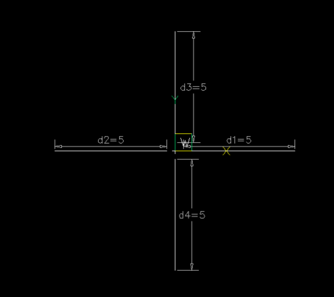
Would going down the dynamic block be a way to always get a Cross at center point of a fixed size then adjust the 4xdistance on the quad legs. Would need a gap distance in the block as say fixed also. I am not the best at dynamic blocks maybe some one else can try it. Using a lisp allows the working out of all the distance parameters and reset them. This would be repeated 4 times. can use D2=D1 and so on. Just did a linear constraint. Trying to remember how to d2=d1.
-
Beyond APPLOAD: A local script manager for those of us with too many LISPs
aridzv replied to VicoWang's topic in AutoLISP, Visual LISP & DCL
1. too many lisp to remember what each one dose. 2. how to bring all of those lisp's up to a new computer. I have 189 lisps at the moment. well, 1. I have a simple excel table of all my lisps, the file name, the command and what they do. every time I add a lisp I add it to the file to keep track and to know what they do if I didn't add description in lisp file at the top as a remark. 2. to load them I don't use appload for each one. I use lisp file with autoload line for each lisp and use appload only for that file,one line only in the appload command. 3. upgrade to a new computer/laptop? copy all the lisp files to the new computer including the autoload lisp, run appload to load that startup lisp, check the "AUTOLOAD" check box and you are done, again - one lisp to load all the others. and if you had dependencies between lisp on the old machine they should work on the new one as well. one side note: for me, When I see a compiled file here on the forum I tend to stay away from it. This forum is built on open source, and compiled code here, at least for me, is some what of a bad taste... -
Centerline is good, it's a centerline, the issue is, CENTERMARK, unless it is a small diameter/radius, it is incorrect according to most standards that I could find and my recollection of manual drafting. I do realize, mine would need some tweaking for the center linetype version and the linetype scale depending on how large the center mark. I think many miss the point of my LISP, it is to replace the default center marks from dimradius and dimdiameter. It also doesn't duplicate shared centers. It is a drawing correction tool for replacing the small marks that can't maintain dimension associativity, the line option makes the correct cross hair, but has the same issues with dimensions, you also cannot alter the color of those centermarks associated with dimdiameter and dimradius. What is put in it's place can be changed. I might try getting something better worked out if more people want it upgraded. From what I could find on the WWW from ASME GD&T standard. IIRC, large radii can have the small mark like in the dimradius/dimdiameter, the issue of associative dimension etc. remain though. On doing some experimenting, CENTERMARK can be made correct by replacing the default linetype from Center to Continuous and a few more tweaks maybe. I'll have to do some testing on resetting the defaults for CENTERMARK, that may just work. LeeMac's Centerline doesn't work on arcs or inside a block, just circles the best I could tell.