All Activity
- Past hour
-

How to Extend Lines to shape 2D Polyline
SLW210 replied to Mountain_XD's topic in AutoLISP, Visual LISP & DCL
Even with AutoCAD probably still pretty fast for fence, but a LISP would help. I tried several things and I can't get AutoCAD 2026 to double extend as per @BIGAL's example. -
How to Extend Lines to shape 2D Polyline
SLW210 replied to Mountain_XD's topic in AutoLISP, Visual LISP & DCL
For future reference, in the supplied .dwg, it's LWPolyline shapes not 2D Polyline shapes as in the title, there is a difference. LWPOLYLINE Layer: "A_Dai_Coc_S_02" Space: Model space Color: BYLAYER Linetype: "Continuous" Handle = 167 Closed Constant width 0'-0" area 5418979.86 square in. (37631.8046 square ft.) perimeter 791'-11 9/32" at point X=22622'-6 5/16" Y=176'-5 5/8" Z= 0'-0" at point X=22784'-3 15/32" Y=141'-6 27/32" Z= 0'-0" at point X=22907'-5 13/32" Y=279'-3 15/16" Z= 0'-0" at point X=22708'-11 1/16" Y=378'-6 5/32" Z= 0'-0" 2D Polyline POLYLINE Layer: "KCS_DIM" Space: Model space Color: BYLAYER Linetype: "Continuous" Handle = 179 Open starting width 0'-0" ending width 0'-0" area 0.00 sq in (0.0000 sq ft) length 2566'-5 17/32" VERTEX Layer: "KCS_DIM" Space: Model space Color: BYLAYER Linetype: "Continuous" Handle = 17b at point, X=23794'-4 1/8" Y=-362'-5 9/32" Z= 0'-0" starting width 0'-0" ending width 0'-0" VERTEX Layer: "KCS_DIM" Space: Model space Color: BYLAYER Linetype: "Continuous" Handle = 17c at point, X=21227'-10 19/32" Y=-362'-5 9/32" Z= 0'-0" starting width 0'-0" ending width 0'-0" END SEQUENCE Layer: "KCS_DIM" Space: Model space Color: BYLAYER Linetype: "Continuous" Handle = 17a If I have time, I'll see what I can come up with. -

Copy blocks to curve according to another curve
HypnoS replied to HypnoS's topic in AutoLISP, Visual LISP & DCL
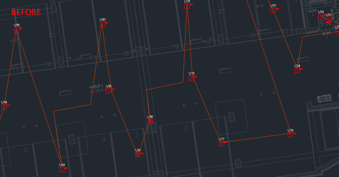
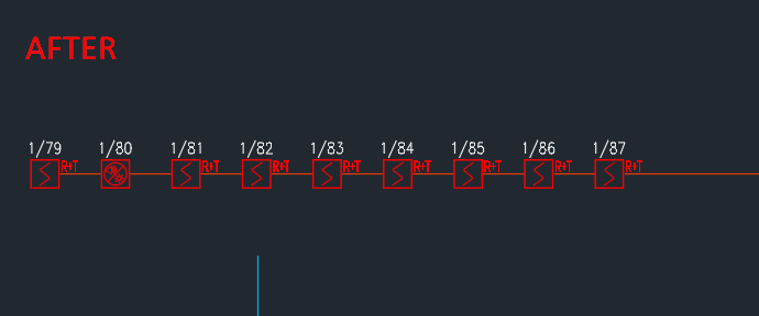
okay so these are dynamic blocks with attributes, thats why i use numpol to change attribute values acording to polyline i drew over them. Now I want to use something like copyblockstocurve (wich works also with polylines) to align my blocks to new straight line in the same order numpol did the numering. So that I could use them to draw a scheme. Example.dwg -
Copy blocks to curve according to another curve
SLW210 replied to HypnoS's topic in AutoLISP, Visual LISP & DCL
That's not a drawing, just images. I don't see a curve. Is the text part of the block? Really need the drawing. -
Copy blocks to curve according to another curve
HypnoS replied to HypnoS's topic in AutoLISP, Visual LISP & DCL

-
Copy blocks to curve according to another curve
SLW210 replied to HypnoS's topic in AutoLISP, Visual LISP & DCL
Can you post a before and after drawing? - Today
-

Break Polyline at different depth
Tsuky replied to Mohamed Haytham's topic in AutoLISP, Visual LISP & DCL
Yet another... (defun c:break_lw ( / js i ent dxf_obj dxf_43 dxf_38 dxf_39 dxf_10 dxf_40 dxf_41 dxf_42 dxf_39 dxf_210 n) (initget "All Select") (if (eq (getkword "\nLWPolylines to break at each vertex? [All/Select] <Select>: ") "All") (setq js (ssget "_X" (list (cons 0 "LWPOLYLINE") (cons 67 (if (eq (getvar "CVPORT") 2) 0 1)) (cons 410 (if (eq (getvar "CVPORT") 2) "Model" (getvar "CTAB"))) ) ) i -1 ) (setq js (ssget (list (cons 0 "LWPOLYLINE") (cons 67 (if (eq (getvar "CVPORT") 2) 0 1)) (cons 410 (if (eq (getvar "CVPORT") 2) "Model" (getvar "CTAB"))) ) ) i -1 ) ) (cond (js (repeat (sslength js) (setq dxf_obj (entget (setq ent (ssname js (setq i (1+ i)))))) (if (cdr (assoc 43 dxf_obj)) (setq dxf_43 (cdr (assoc 43 dxf_obj))) (setq dxf_43 0.0) ) (if (cdr (assoc 38 dxf_obj)) (setq dxf_38 (cdr (assoc 38 dxf_obj))) (setq dxf_38 0.0) ) (if (cdr (assoc 39 dxf_obj)) (setq dxf_39 (cdr (assoc 39 dxf_obj))) (setq dxf_39 0.0) ) (setq dxf_10 (mapcar 'cdr (vl-remove-if-not '(lambda (x) (= (car x) 10)) dxf_obj)) dxf_40 (mapcar 'cdr (vl-remove-if-not '(lambda (x) (= (car x) 40)) dxf_obj)) dxf_41 (mapcar 'cdr (vl-remove-if-not '(lambda (x) (= (car x) 41)) dxf_obj)) dxf_42 (mapcar 'cdr (vl-remove-if-not '(lambda (x) (= (car x) 42)) dxf_obj)) dxf_210 (cdr (assoc 210 dxf_obj)) ) (if (not (zerop (boole 1 (cdr (assoc 70 dxf_obj)) 1))) (setq dxf_10 (append dxf_10 (list (car dxf_10))) dxf_40 (append dxf_40 (list (car dxf_40))) dxf_41 (append dxf_41 (list (car dxf_41))) dxf_42 (append dxf_42 (list (car dxf_42))) n (cdr (assoc 90 dxf_obj)) ) (setq n (1- (cdr (assoc 90 dxf_obj)))) ) (repeat n (entmake (list (cons 0 "LWPOLYLINE") (cons 100 "AcDbEntity") (assoc 67 dxf_obj) (assoc 410 dxf_obj) (assoc 8 dxf_obj) (if (assoc 62 dxf_obj) (assoc 62 dxf_obj) (cons 62 256)) (if (assoc 6 dxf_obj) (assoc 6 dxf_obj) (cons 6 "BYLAYER")) (if (assoc 370 dxf_obj) (assoc 370 dxf_obj) (cons 370 -1)) (cons 100 "AcDbPolyline") (cons 90 2) (cons 70 (boole 1 (cdr (assoc 70 dxf_obj)) 128)) (cons 38 dxf_38) (cons 39 dxf_39) (cons 10 (car dxf_10)) (cons 40 (car dxf_40)) (cons 41 (car dxf_41)) (cons 42 (car dxf_42)) (cons 10 (cadr dxf_10)) (cons 40 (cadr dxf_40)) (cons 41 (cadr dxf_41)) (cons 42 (cadr dxf_42)) (assoc 210 dxf_obj) ) ) (setq dxf_10 (cdr dxf_10) dxf_40 (cdr dxf_40) dxf_41 (cdr dxf_41) dxf_42 (cdr dxf_42)) ) (entdel ent) ) (print (sslength js)) (princ " LWpolyline(s) breaked at its vertexs.") ) ) (prin1) ) -

Autocad 2010 Fuzz distance ?
oddssatisfy replied to Robbio's topic in AutoCAD 3D Modelling & Rendering
The error means your mesh likely has self-intersections or is not watertight. Fuzz distance won’t fix this. You need to clean up the mesh, close any gaps, and remove overlapping geometry before converting it to a solid. Use a mesh repair tool to fix these issues. -
Copy blocks to curve according to another curve
HypnoS posted a topic in AutoLISP, Visual LISP & DCL
Hi all, I was wondering if someone could help me with a lisp modyfication. I need to modify CopyBlockStoCurve lisp so I don't need to select each block individually co copy it to the curve. I thought why not copy a function from numpol, which numbers blocks according to a polyline. So I need the new CopyBlockStoCurve to arrange blocks on a curve, but in accordance with how the blocks are positioned on another polyline basiclly. Can anyone help? numpol.lspCopyBlocksToCurve.lsp -

Break Polyline at different depth
Emmanuel Delay replied to Mohamed Haytham's topic in AutoLISP, Visual LISP & DCL
Exploding polylines makes lines. Lines have no width. The question is to "explode", but keep all edges as polyline with the original width -

Break Polyline at different depth
marko_ribar replied to Mohamed Haytham's topic in AutoLISP, Visual LISP & DCL
I might be wrong, but can this be achieved just by using EXPLODE command? [EDIT : I see it now... EXPLODE command converts segments into LINE and ARC entities, so widths are lost...] - Yesterday
-

Break Polyline at different depth
ronjonp replied to Mohamed Haytham's topic in AutoLISP, Visual LISP & DCL
Another for fun: (defun c:foo (/ a b el l s) ;; RJP » 2025-07-21 ;; Creates separate polyline segments preserving widths etc.. (cond ((setq s (ssget '((0 . "LWPOLYLINE")))) (foreach e (vl-remove-if 'listp (mapcar 'cadr (ssnamex s))) (setq el (entget e)) (setq a (append (reverse (member '(100 . "AcDbPolyline") (reverse el))) '((90 . 2)))) (setq b (vl-remove-if-not '(lambda (x) (member (car x) '(10 40 41 42))) el)) (while (cddddr b) (setq l nil) (setq l (list (car b) (cadr b) (caddr b) (cadddr b))) (setq b (cddddr b)) (entmakex (append a (append l (list (car b) (cadr b) (caddr b) (cadddr b))))) ) (entdel e) ) ) ) (princ) )
-

Break Polyline at different depth
Nikon replied to Mohamed Haytham's topic in AutoLISP, Visual LISP & DCL
Try this code ;; author ::Jaifl:: ;; divides polylines into separate segments, preserving thickness, color, layer (defun c:SplitPlSeg ( / ss i ent elist points widths bulges n j p1 p2 w1 w2 bulge color layer ltype lweight transp) (setq ss (ssget '((0 . "LWPOLYLINE")))) (if ss (progn (setq i 0) (while (< i (sslength ss)) (setq ent (ssname ss i)) (setq elist (entget ent)) (setq color (assoc 62 elist)) (setq layer (assoc 8 elist)) (setq ltype (assoc 6 elist)) (setq lweight (assoc 370 elist)) (setq transp (assoc 440 elist)) (setq points '() widths '() bulges '()) (foreach x elist (cond ((= (car x) 10) (setq points (append points (list (cdr x))))) ((= (car x) 40) (setq widths (append widths (list (cdr x))))) ((= (car x) 41) (setq widths (append widths (list (cdr x))))) ((= (car x) 42) (setq bulges (append bulges (list (cdr x))))) ) ) (setq n (length points)) (setq j 0) (while (< j (1- n)) (setq p1 (nth j points)) (setq p2 (nth (+ j 1) points)) (setq w1 (nth (* j 2) widths)) ; Start width (setq w2 (nth (1+ (* j 2)) widths)) ; End width (setq bulge (if (< j (length bulges)) (nth j bulges) 0.0)) (setq newent (append (list (cons 0 "LWPOLYLINE") (cons 100 "AcDbEntity") layer ) (if color (list color) '()) (if ltype (list ltype) '()) (if lweight (list lweight) '()) (if transp (list transp) '()) (list (cons 100 "AcDbPolyline") (cons 90 2) (cons 70 0) (list 10 (car p1) (cadr p1)) (cons 40 w1) (cons 41 w2) (cons 42 bulge) (list 10 (car p2) (cadr p2)) (cons 40 w2) (cons 41 w2) ) ) ) (entmake newent) (setq j (1+ j)) ) (entdel ent) ; delete the original polyline (setq i (1+ i)) ) ) (princ "There are no selected polylines.") ) (princ) ) -
Hi, It would be great if you can help me with the following. I have multiple polylines where they have different widths (Originally creating by fillet a line with width 1 and a line with width 2). Is there a way to split them to the original state where the are 2 lines and each has it's actual widths? I am attaching a file with the issue, and the expected solution, but this is only file with 2 polylines as an example, but this issue is happening with a file having more than 1000 polyline. Break Polyline at different depth.dwg
-
How to Extend Lines to shape 2D Polyline
SLW210 replied to Mountain_XD's topic in AutoLISP, Visual LISP & DCL
AutoCAD refuses to double extend for some reason. - Last week
-
updating samples, this one is cool import traceback from pyrx import Rx, Ge, Gs, Db, Ap, Ed import wx import os # extract the image and save it def extractThumbnailsFromDb(db: Db.Database, path: str, targetpath: str): path_without_extension, _ = os.path.splitext(path) dwgname = os.path.basename(path_without_extension) bt = Db.BlockTable(db.blockTableId()) for name, id in bt.asDict().items(): blk = Db.BlockTableRecord(id) if ( blk.isLayout() or blk.isAnonymous() or blk.isFromExternalReference() or blk.isFromOverlayReference() ): continue img: wx.Image = Gs.Core.getBlockImage(id, 128, 128, 1.0, [0, 0, 0]) img.SaveFile("{}/{}_{}_128.png".format(targetpath, dwgname, name), wx.BITMAP_TYPE_PNG) # read the database in its own function so the database object # gets disposed after the blocks (gc is fifo) def extractThumbnails(path: str, targetpath: str): db = Db.Database(False, True) db.readDwgFile(path) db.closeInput(True) extractThumbnailsFromDb(db, path, targetpath) # register a new command # ensure the targetpath exists @Ap.Command() def doit(): try: targetpath = "E:/temp/icons" os.makedirs(targetpath, exist_ok=True) for path in Ap.Application.listFilesInPath("E:\\temp", ".dwg"): extractThumbnails(path, targetpath) except Exception as err: traceback.print_exception(err)
-
- 1
-

-

How to Extend Lines to shape 2D Polyline
ScottMC replied to Mountain_XD's topic in AutoLISP, Visual LISP & DCL
BIGAL that helps for sure! All the more inspires me to dig deeper into your posts/tips period. -
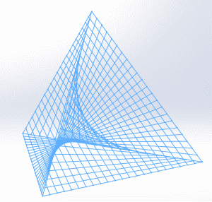
I just started to do some VB in SolidWorks. So this is my first try: Option Explicit Dim swModel As SldWorks.ModelDoc2 Sub main() Dim aLine As SldWorks.SketchSegment Dim line As Object Set swModel = Application.SldWorks.ActiveDoc swModel.SketchManager.Insert3DSketch True 'tetrahedron side length Dim L As Double 'doh... number of segments Dim segs As Integer L = 10 segs = 22 Dim Xa, Ya, Za As Double 'point A is in the origin Xa = 0 Ya = 0 Za = 0 Dim Xb, Yb, Zb As Double 'point B is along Ox Xb = L Yb = 0 Zb = 0 Dim Xc, Yc, Zc As Double 'point C is in xOy plane Xc = L / 2# Yc = L * Sqrt(3) / 2# Zc = 0 Dim Xv, Yv, Zv As Double ' point V is right above the centroid of ABC Xv = L / 2# Yv = L * Sqrt(3) / 6 Zv = L * Sqrt(6) / 3# Dim i As Integer 'point1 walks along AV Dim Dx1, Dy1, Dz1, Dx2, Dy2, Dz2 As Double Dx1 = (Xv - Xa) / segs Dy1 = (Yv - Ya) / segs Dz1 = (Zv - Za) / segs 'point2 walks along BC Dx2 = (Xc - Xb) / segs Dy2 = (Yc - Yb) / segs Dz2 = (Zc - Zb) / segs 'point3 walks along BV Dim Dx3, Dy3, Dz3, Dx4, Dy4, Dz4 As Double Dx3 = (Xv - Xb) / segs Dy3 = (Yv - Yb) / segs Dz3 = (Zv - Zb) / segs 'point4 walks along CA Dx4 = (Xa - Xc) / segs Dy4 = (Ya - Yc) / segs Dz4 = (Za - Zc) / segs 'point5 walks along CV Dim Dx5, Dy5, Dz5, Dx6, Dy6, Dz6 As Double Dx5 = (Xv - Xc) / segs Dy5 = (Yv - Yc) / segs Dz5 = (Zv - Zc) / segs 'point6 walks along AB Dx6 = (Xb - Xa) / segs Dy6 = (Yb - Ya) / segs Dz6 = (Zb - Za) / segs 'draw those lines: For i = 0 To segs 'lines between point1 and point2: Set aLine = Draw(Xa + Dx1 * i, Ya + Dy1 * i, Za + Dz1 * i, Xb + Dx2 * i, Yb + Dy2 * i, Zb + Dz2 * i) 'the lines between point3 and point4: Set aLine = Draw(Xb + Dx3 * i, Yb + Dy3 * i, Zb + Dz3 * i, Xc + Dx4 * i, Yc + Dy4 * i, Zc + Dz4 * i) 'the segments between point5 and point6 Set aLine = Draw(Xc + Dx5 * i, Yc + Dy5 * i, Zc + Dz5 * i, Xa + Dx6 * i, Ya + Dy6 * i, Za + Dz6 * i) Next i ' Close sketch swModel.SketchManager.InsertSketch True 'swModel.ClearSelection2 True End Sub Function Draw(X1, Y1, Z1, X2, Y2, Z2 As Double) As SldWorks.SketchSegment Set Draw = swModel.SketchManager.CreateLine(X1, Y1, Z1, X2, Y2, Z2) End Function
-

Tapered Offset/Stretch closed polyline shape
GLAVCVS replied to SLW210's topic in AutoLISP, Visual LISP & DCL
Hi, Here’s a preview of what the new Offsetea will look like. Sorry for the delay — I’ve had other things to take care of. Still, I believe the wait will be worth it. Each improvement leads to another... but I think I'm going to stop here I still need to fine-tune a few things, but the final result will be very close to what you see in the clip: -Projection of straight line segments -3 projection modes for arc segments (one of them is the same as the one Evgeny proposed in his code) + 1 custom mode that I still have to write. Switching between modes is as simple as pressing keys 1, 2, 3, or 4 -Snapping to adjust position with the cursor -Real-time "texting" using grread in all cases -Voice assistance to provide useful info I'll try to finish it this week, but I can’t promise anything — I’ve got quite a bit of work. Still, I hope that with this small preview I’ve earned a bit of your patience Offsetea Reloaded.mp4 -

How to Extend Lines to shape 2D Polyline
mhupp replied to Mountain_XD's topic in AutoLISP, Visual LISP & DCL
Going to have to click a little then. or use fence like BIGAL shows. -

How to Extend Lines to shape 2D Polyline
BIGAL replied to Mountain_XD's topic in AutoLISP, Visual LISP & DCL
Interesting Bricscad using "Fence" option. No code needed.
-
Looks good, next option would be "Add breaklines" to make the TIN take into account edges.
-
How to Extend Lines to shape 2D Polyline
ScottMC replied to Mountain_XD's topic in AutoLISP, Visual LISP & DCL
Consider this link with multiple solutions https://www.theswamp.org/index.php?topic=53993.0 -
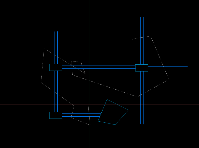
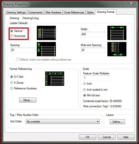
What version of AutoCAD Electrical? Unless it's changed, you go to Drawing Properties under the Drawing Format tab and select "Vertical" under Ladder Defaults. Maybe this will help... AutoCAD Electrical 2025 Help | To Work With Ladders | Autodesk
-

How to deploy list of Lisps to everyone in the organisation - AutoCAD LT
Steven P replied to CivilTechSource's topic in AutoLISP, Visual LISP & DCL
Sorry BigAl, I was forgetting BricsCAD - I've never used it so no sure what it has and doesn't