All Activity
- Past hour
-

Selecting Folders (AutoCAD LT 2024)
Steven P replied to SLW210's topic in AutoLISP, Visual LISP & DCL
yes, good idea. - Today
-
I Agree with Lee I'm interested in what your actually doing. take this for example. different approaches lisps that have a large range of run times. all basically doing the same thing. mine still took over a min to run, but ronjonp came in with 4.07 sec. theirs built an main list processed that list into smaller lists. once processed removed the items from each lists. (speeds up search)
-
Here is my latest zoom .9x in all layouts. I hadn't noticed the OP posted a .dwg, so i ran my Viewport Border into Model code on it. Is the result you wanted? ====================================== AutoVPBrdr REPORT ====================================== True layout viewports: 4 Viewport layer assignments: 4 Layer assignment failures: 0 Modelspace borders created: 3 Viewports skipped: 1 -------------------------------------- Layer: Viewport Color: 45 Plot: OFF ====================================== ZE_Z9XP_1.1.lsp
-
@PGia While it's very possible to create variables on the fly. I agree with Lee that it should not be a method to use, especially in the way you are wanting to use it. That being said, I wrote the following many years ago, but hardly have ever used it for anything. It accepts an assoc. list of strings representing variables and the corresponding values, then creates a variable for each with the value. The core of it is very simple (set (read "StrVar") value) ;|============================================================================== Function Name: (pjk-dynsetvar) Arguments: assoclst = List of cons; an assoc list on the format: (list (cons "<var name1>" <value1>) ... (cons "<Var namN>" <valueN>)) Usage: (pjk-dynsetvar <Assoc. List>) Ex: (pjk-dynsetvar (list (cons "Cenpt" (list 1.0 1.0 0.0)) (cons "Radius" 0.25))) Returns: The results of the read list. You can verify the variables with the ! prefix: Command line Example: Command: (pjk-dynsetvar (list (cons "Cenpt" (list 1.0 1.0 0.0)) (cons "Radius" 0.25))) ((1.0 1.0 0.0) 0.25) Command: !Cenpt (1.0 1.0 0.0) Command: !Radius 0.25 Description: This function dynamically sets AutoLISP variables based on an association list of strings and values. The string keys represent the names of the variables that the values will be assigned to. ================================================================================|; (defun pjk-DynSetVar (assoclst) (mapcar (function (lambda (x)(set (read (car x)) (cdr x)))) assoclst) ) ;; End Function (pjk-dynsetvar)
-
It seems it's not placing CENTERMARKS in Mechanical, I haven't tested other verticals from the toolset, it does use my fallback CrossHairs, though. I may not bother getting CENTERMARK to work in verticals unless someone else is interested, I would use the LISP in AutoCAD anyway, but I will do some testing on Mechanical/Architectural drawings in AutoCAD when I have time. Speaking of time, does anyone have a LISP or something that can give me a 30+ hour day, maybe @rlx I'll try to check this latest version in AutoCAD 2000i this weekend.
-

How do you verify the accuracy of a 3D model before creating production drawings?
SLW210 replied to indiancad's topic in AutoCAD 3D Modelling & Rendering
For most parts to be manufactured, fully dimensioning the 2D drawing would show any errors, I have never worked anywhere that manufactured from the 3D model, always needed a 2D drawing fully dimensioned. Though, I suppose for arguments sake, possibly could just make a model, create the 2D profiles and send them to a waterjet/plasma cutter, in that instance I would dimension relevant places/points and remove the dimensions before sending the profile, though in reality, I always create a fully dimensioned 2D anyway and I have sent the waterjet programmer the dimensioned profile if requested, it can be made a non-path object or deleted there. I rarely need specific dimensions on my 3D prints, though I draw them to a specific size usually, the ones that need mating parts I do same as you, but then again, creating 2D profiles, sections etc. can be of great help. -

How do you verify the accuracy of a 3D model before creating production drawings?
indiancad posted a topic in AutoCAD 3D Modelling & Rendering
A 3D model can look correct from every viewing angle, but small geometric errors may only become noticeable when preparing manufacturing drawings. For critical parts, I check important dimensions, inspect the model from different directions, and compare key cross-sections against the design requirements. I also avoid relying only on shaded views because they can hide small gaps, incorrect alignments, or geometric deviations. What checks do you normally perform before approving a 3D model for manufacturing? -
Thanks for your answer, @Lee Mac. I've tried creating a list with the coordinates of almost 20,000 objects and managing it on the fly with assoc and subst. However, the processing speed is quite slow. For this reason, it occurred to me to try dynamic variables. You're probably right. But in your answer, you seem to concede a small possibility that using them might actually be worthwhile. What do you mean by that?
- Yesterday
-

Aluminum composite panels parametric templates
BIGAL replied to emosms's topic in AutoCAD 2D Drafting, Object Properties & Interface
Ok this is just a start to show how it could be done. Save the Multi getvals.lsp to a support path as its a library lisp that can be used in any code. Or edit the (load "C:\\fullpath\\multigetvals") Just enter rows and cols as 1 only option started at this stage. ; https://www.cadtutor.net/forum/topic/99378-aluminum-composite-panels-parametric-templates/ : draw panels by AlanH Nov 2026 (defun c:wow ( / ans cols dimoff horizontalonly lay laylst lwt multipanels pt pt1 pt2 pt3 pt4 rows singlepanel verticalonly wid ht top bot left right )Multi GETVALS.lspMulti radio buttons.lsp (defun singlepanel ( / ) (setq ans (AH:getvalsm (list "Enter values " "Width " 5 4 "400" "Height " 5 4 "300" "Top " 5 4 "25" "Bottom " 5 4 "25" "Left" 5 4 "20" "Right" 5 4 "20" ))) (setq wid (atof (nth 0 ans)) ht (atof (nth 1 ans)) top (atof (nth 2 ans)) bot (atof (nth 3 ans)) left (atof (nth 4 ans)) right (atof (nth 5 ans))) (Command "pline" pt "w" lwt "" (polar Pt 0.0 wid) (polar (getvar 'lastpoint) (/ pi 2.) ht) (polar (getvar 'lastpoint) pi wid) "C") (princ) ) (defun verticalonly ( / ) (alert "vertical1only") (princ) ) (defun horizontalonly ( / ) (alert "horizontaly1only") (princ) ) (defun multipanels ( / ) (alert "Multipanels") (princ) ) (if (not AH:getvalsm)(load "Multi Getvals.lsp")) (if (not AH:Butts)(load "Multi radio buttons.lsp")) ; loads the program if not loaded already (setq but 1) ; this is needed to set default button for mkulti radios (setq ans (AH:getvalsm (list "Enter values " "Number Hor panels" 5 4 "2" "Number Vertical panels" 5 4 "2" "NAME" 20 19 "" "PCS" 20 19 "PCS"))) (setq cols (atoi (nth 0 ans)) rows (atoi (nth 1 ans)) pname (nth 2 ans) pcs (nth 3 ans)) (setq dimoff 15 lwt 0.7) (setq pt (getpoint "\nPick lower left point ")) (cond ((and (= rows 1)(= cols 1))(singlepanel)) ((and (> rows 1)(= cols 1))(verticalonly)) ((and (= rows 1)(> cols 1))(horizontalonly)) ((and (> rows 1)(> cols 1))(multipanels)) (progn (alert "something is wrong in your rows and columns\nWill exit now. Please redo")(exit)) ) (setq laylst (list '("_F" 4) '("_R" 3) '("_DIM" 32))) (foreach lay laylst (if (tblsearch "layer" (car lay)) (princ lay) (command "-layer" "M" (car lay) "c" (cadr lay) "" "LW" 0.0 "" "") ) ) (princ) ) (c:wow) Let me know what you think about this idea. Multi radio buttons.lsp Multi GETVALS.lsp -
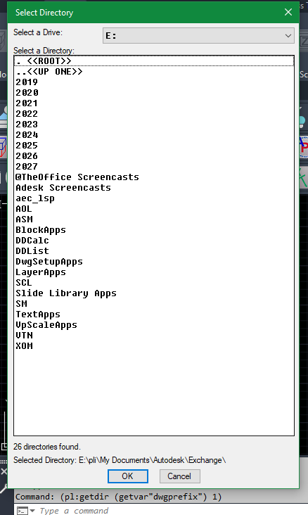
@Steven P A couple of suggestions (defun MakeDriveList ( / replace with (if (not AH:Butts)(load "Multi radio buttons.lsp")) ; loads the program if not loaded already (setq drivelist (ah:butts 1 "V" '("Please choose" "C:" "D:" "E:" "F:"))) "(setq GetFolderDcl (load_dialog "GetFolder"))" I use the write dcl to lisp by RLX so dcl code can live in the master lisp, then only one file. You may be able to use powershell to dump out the correct drives including network drives to a file and read that with lisp, done via a (startapp c:\path\drives.bat) powershell Get-PSDrive -PSProvider FileSystem | Out-File -FilePath "D:\acadtemp\drives_list.txt" exit Convert dcl 2 lisp rlx.lsp Multi radio buttons.lsp
-
Selecting Folders (AutoCAD LT 2024)
Steven P replied to SLW210's topic in AutoLISP, Visual LISP & DCL
Frustratingly I think it has a couple of VLAX functions but not all of them - for LT I'd be finding another way if possible (in my example above bypassing the functionality completely) -
A couple of points to make: The need to create thousands of variables on-the-fly typically points to poor program design; in almost every case, a list is more suitable. Setting all such variables to nil at the end of the program does clear them from the document namespace, but consider that you are essentially creating & clearing global variables that are not local to the scope of your program, and as such, the variable names could potentially clash with identically named variables in the document namespace - this is generally considered bad practice.
-
Hi again. There's something I can't seem to find a clear answer to. Maybe someone here can give me that answer. I'm experimenting with the use of dynamic variables, created in real-time. However, there's something that often makes me doubt whether it's advisable to use them. And that's where my question lies: If my code creates thousands of variables to avoid having to store data in a structure (lists or arrays)... when at the end of the code I cancel each of those variables with (set 'v nil), do the names of those variables really disappear from AutoCAD's symbol table, or only their content? I know about the atoms-family function and that it returns the value of a symbol if it exists. But the AI says that a negative response from atoms-family is not a guarantee that the symbol no longer exists in AutoCAD's internal symbol table. Thanks in advance.
-
How do you create a mirrored 3D part across an angled plane?
indiancad posted a topic in AutoCAD 3D Modelling & Rendering
When modelling symmetrical components, the mirror plane is not always parallel to the standard XY, YZ, or XZ planes. The MIRROR3D command makes this easier by allowing you to define a custom mirror plane using three points. This is useful when creating matching components for angled brackets, machine parts, or other non-standard shapes. After mirroring, I also check the position and orientation of the new solid. Have you used MIRROR3D with a custom plane? What method do you prefer for creating symmetrical 3D parts? -
How do you align two 3D parts without adjusting their position manually?
indiancad posted a topic in AutoCAD 3D Modelling & Rendering
When assembling a 3D model, positioning one component accurately against another can be difficult, especially when both parts are at different angles. Instead of repeatedly using MOVE and ROTATE3D, 3DALIGN can help. By selecting matching points on both objects, you can position and orient one part accurately. I find this useful when assembling mechanical components or placing parts into an existing model. Do you use 3DALIGN for positioning 3D components, or do you prefer to adjust their position manually? -
Why does SWEEP twist a profile while following a curved path?
indiancad replied to indiancad's topic in AutoCAD 2D Drafting, Object Properties & Interface
THANKS FOR SHARING! -
Why does SWEEP twist a profile while following a curved path?
indiancad replied to indiancad's topic in AutoCAD 2D Drafting, Object Properties & Interface
YES!circular profiles in piping, twisting is usually less noticeable. Thanks for sharing your experience. - Last week
-

Selecting Folders (AutoCAD LT 2024)
Paul Li replied to SLW210's topic in AutoLISP, Visual LISP & DCL
@BIGAL you're correct...in fact functions attempting to access 3rd party apps like Excel are all not supported: https://help.autodesk.com/view/ACDLT/2024/ENU/?guid=GUID-037BF4D4-755E-4A5C-8136-80E85CCEDF3E -
The other important one missing is Vlax-get-application it allows you to talk to Excel via lisp.
-
Generated ISO title block DXF: units, attributes and fonts when used in a template
BIGAL replied to Margo App's topic in AutoCAD Drawing Management & Output
There is auto make layouts, choosing size and scale of viewport, a couple of options like pick a point, enter scale and title block needed, add rectangs for title block in Model at scale and make new layouts, a couple of different methods. Draw rectangs.mp4 Just ask if interested.
-
Why does SWEEP twist a profile while following a curved path?
lrm replied to indiancad's topic in AutoCAD 2D Drafting, Object Properties & Interface
@indiancad here's a thread that you might find interesting regarding twist relative to a spline. Note that the first derivative of a curve is a vector tangent to the spline at a specifed point on the spline. The second derivative is a vector thet is the direction and magnitude of the change in the tangent vector at a point. The cross product of these two vetors, also know as the transverse vector, point to the instantaneous center of curvature for the curve at a specfied point along a curve. I wrote the following program to display graphically the radius of curvature (the ends of the generated lines are the center of curvature) or the curvature of a spline (short lines indicate almost flat segments of a spline). Try the program on a spline and answer Yes when prompted. (defun C:DOCL (/ path inc n osm par der1 der2 curva p perp normv p2 sf curveType ans) ; = Degree Of Curvature - Lines ; Creates curvature lines or radius-of-curvature lines ; normal to a spline. ; LRM 8/18/2022 edited to place curvature vectors outside (setq path (car (entsel)) inc (/ (vlax-curve-getEndParam path) 100) n 0 osm (getvar 'osmode) ) (setvar 'osmode 0) (setvar "cmdecho" 0) (initget "y n") (setq ans (getkword "Do you want radius-of-curvature instead of curvature? [y/n] <n>: ")) (if (= ans "y") (setq curveType 1) (setq curveType 2 sf (getdist "Enter scale factor.") ) ) (repeat 100 (setq par (* inc n)) (setq der1 (vlax-curve-getfirstDeriv path par) der2 (vlax-curve-getSecondDeriv path par) ) ; calculate curvature at point par (setq d (distance '(0 0 0) (cross der1 der2))) (if (> (abs d) 1.0e-15) (progn (setq curva (/ (expt (distance '(0 0 0) der1) 3) d)) (if (= curveType 2) (setq curva (* -1. (* sf (/ 1. curva)))) ) (princ "\n") (princ n) (princ " curvature = ") (princ curva) (setq p (vlax-curve-getPointAtParam path par) perp (unitv (cross der1 (cross der2 der1))) normv (mapcar '* perp (list curva curva curva)) p2 (mapcar '+ p normv) ) (command "_.line" p p2 "") ) ; end progn ) (setq n (1+ n)) ) (setvar 'osmode osm) (setvar "cmdecho" 1) (princ) ) ;;; Compute the cross product of 2 vectors a and b (defun cross (a b / crs) (setq crs (list (- (* (nth 1 a) (nth 2 b)) (* (nth 1 b) (nth 2 a)) ) (- (* (nth 0 b) (nth 2 a)) (* (nth 0 a) (nth 2 b)) ) (- (* (nth 0 a) (nth 1 b)) (* (nth 0 b) (nth 1 a)) ) ) ;end list ) ;end setq c ) ;end cross (defun unitV ( v / d) (setq d (distance '(0 0 0) v) d (mapcar '/ v (list d d d)))) blocks_on_spline.lsp spline curvature.lsp -
Selecting Folders (AutoCAD LT 2024)
Paul Li replied to SLW210's topic in AutoLISP, Visual LISP & DCL
FYI: LT 2024+ does support vlax functions but not vlax-create-object -
Selecting Folders (AutoCAD LT 2024)
Paul Li replied to SLW210's topic in AutoLISP, Visual LISP & DCL
and yet here's another version that should run in LT pl_GetDir.lsp
-
I think I have a ready for testing version ready. If I have time I'll try it on AutoCAD 2000i on my home computer as well. Let me know if you have issues, I tested it in a few cases on AutoCAD 2026. I still have a few things I want to add to it for myself, maybe some reactors for the CrossHairs, I might add a DCL for the Layer information, et. al. ;;; Add AutoCAD's Native CENTERMARK (option for a crosshair of lines) to Diameter/Radius dimension and turns off the Center Mark/Line if on. ;;; ;;; https://www.cadtutor.net/forum/topic/99350-center-mark-replacement/#findComment-680408 ;;; ;;; By SLW210 (a.k.a. Steve Wilson) ;;; ;;; Since AutoCAD in there infinite wisdom makes the default dimdia and dimrad center marks useless ;;; by not allowing them to be associated by other dimensions and not allowing an individual color and linetype. ;;; I came up with this little routine. Much faster, it was using some commands, I went to removing commands. Though ;;; for CENTERMARK, a command is needed so there remains those that are necessary. ;;; I used to get rid of the default then drew a centermark and copied from center to center, a bit tedious at best. ;;; ;;; I started with this from Alan J Thompson, so thanks to him. ;;; ================================================================ ;;; Turn off the centermark for diameter and radius dimensions ;;; ;;; https://www.cadtutor.net/forum/topic/18792-request-routint-to-turn-off-center-mark-for-single-entity/#findComment-153451 ;;; ;;; By alanjt|; ;;; *********************************************************************************************************************************| ;;; <<One word of warning: This could remove Dimension Associativity.>> | ;;; In testing DIMRAD/DIMDIA with Center Mark on in sub-Dimstyles or as Overrides lost associativity when removing Center Marks. | ;;; *********************************************************************************************************************************| ;;; ================================================================ ;;; ================================================================ ;;; AddCtrMrk.lsp ;;; ;;; ;;; AutoCAD 2018-2026 should work as well as BricsCAD and others. ;;; Even if there is not a CENTERMARK command, it should use the CrossHair fallback. ;;; ;;; ================================================================ ;;; ================================================================ ;;; Original dimensions are retained. ;;; ;;; Replacement geometry: ;;; Layer : CenterMark ;;; Color : ByLayer ;;; Linetype : ByLayer ;;; Layer Color : ACI 5 (Blue) ;;; Layer Linetype : ByLayer ;;; ;;; Options: ;;; Native -uses AutoCAD's (or other) native CENTERMARK command (if available) ;;; Crosshair -uses the inbuilt CrossHair made of lines and automatically sized to the curve object ;;; Auto -Automatically selects native CENTERMARK if available or uses CrossHair if not available ;;; ;;; Modes: ;;; Select - manually selected DIMDIAMETER/DIMRADIUS (This LISP works on the dimension not the Arc, Circle, etc., so select the dimension) ;;; Current - all such dimensions in current Model/Layout space ;;; All - all such dimensions in all paperspace layouts + Model ;;; ;;; Associated dimension center marks: ;;; Disabled using acCenterNone. ;;; ;;; Duplicate centers: ;;; Only one Centermark or CrossHair is created for each unique center ;;; within each Model/Layout space using a center tolerance. ;;; ================================================================ Hopefully some my find this useful. I have done some more testing and a little bit of tweaking here and there to make some improvements. It failed on my AutoCAD 2000i, I'll worked some on that, but still need more testing at home. I did notice one issue which cannot be avoided so far, as noted now in the header. This actually happens even turning them off through properties. Though has only happened on a particular test drawing, so may not happen all of the time. I am still checking in to it. AddCtrMrk_1.7.lsp
-
 Ryan Z joined the community
-

Generated ISO title block DXF: units, attributes and fonts when used in a template
Margo App replied to Margo App's topic in AutoCAD Drawing Management & Output
Thanks BIGAL, and sorry for the late reply. One layout per sheet size, each holding only the title sheet at true size, is exactly the setup I was missing. I've added it to the notes that come with the DXF files: insert the sheet at 0,0 and scale 1 in a layout named after the size, make one layout per size, save as .dwt, then bring in the one you need with LAYOUT > Template. Thanks also for the Lisp document and the welcome.