All Activity
- Past hour
-
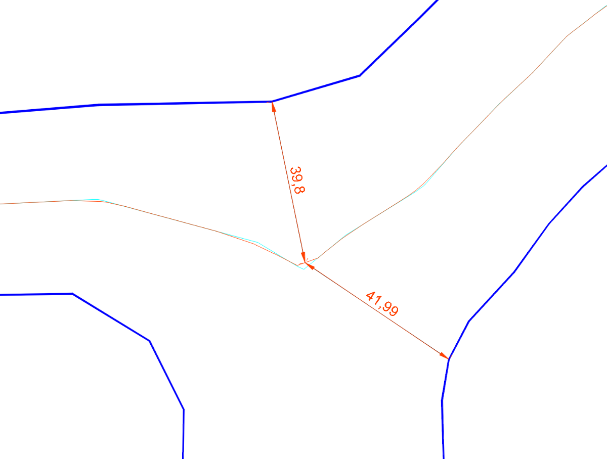
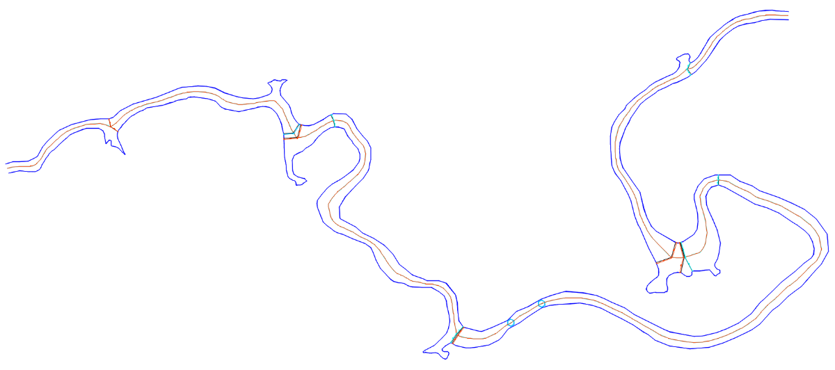
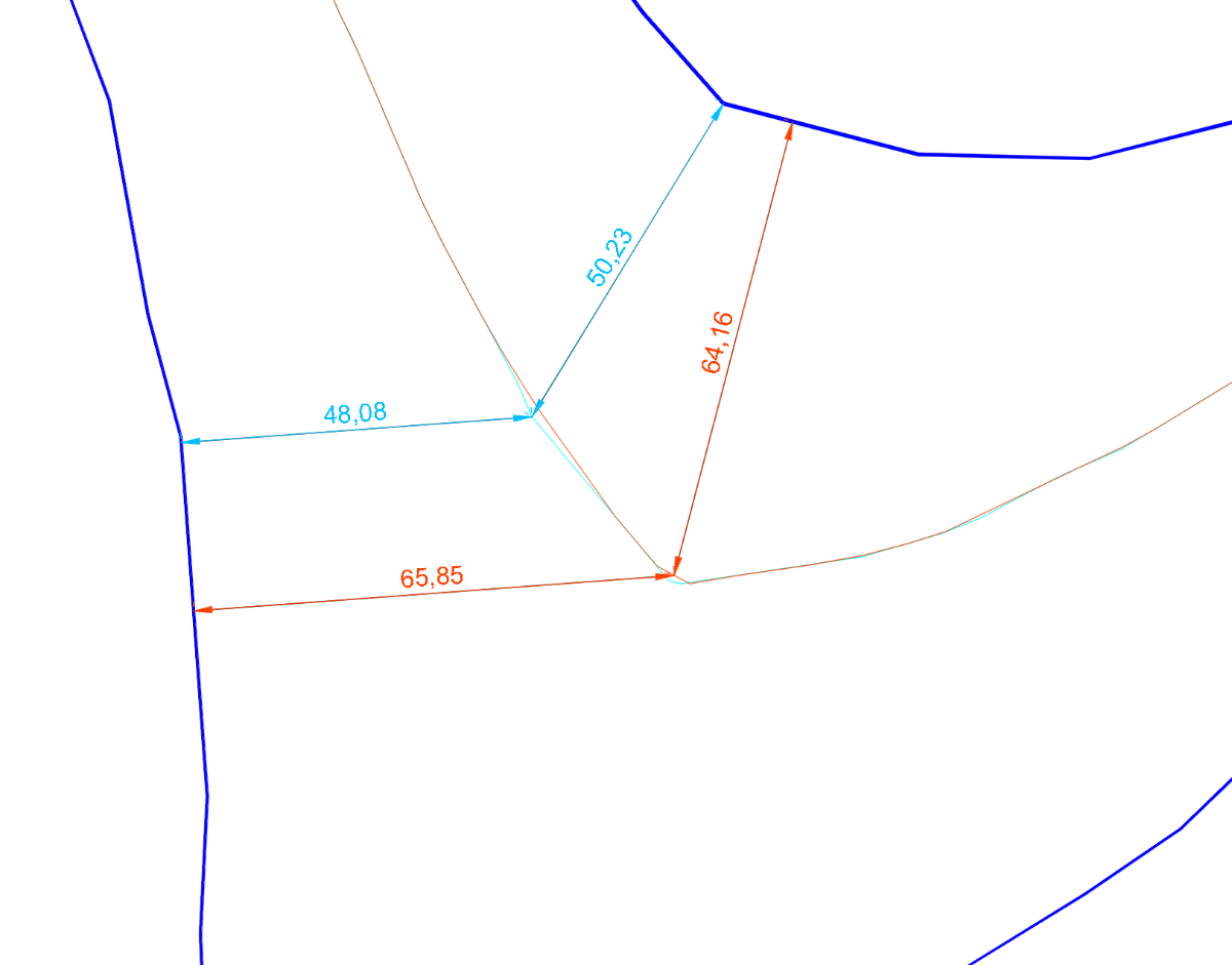
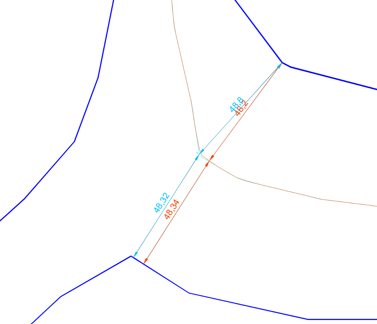
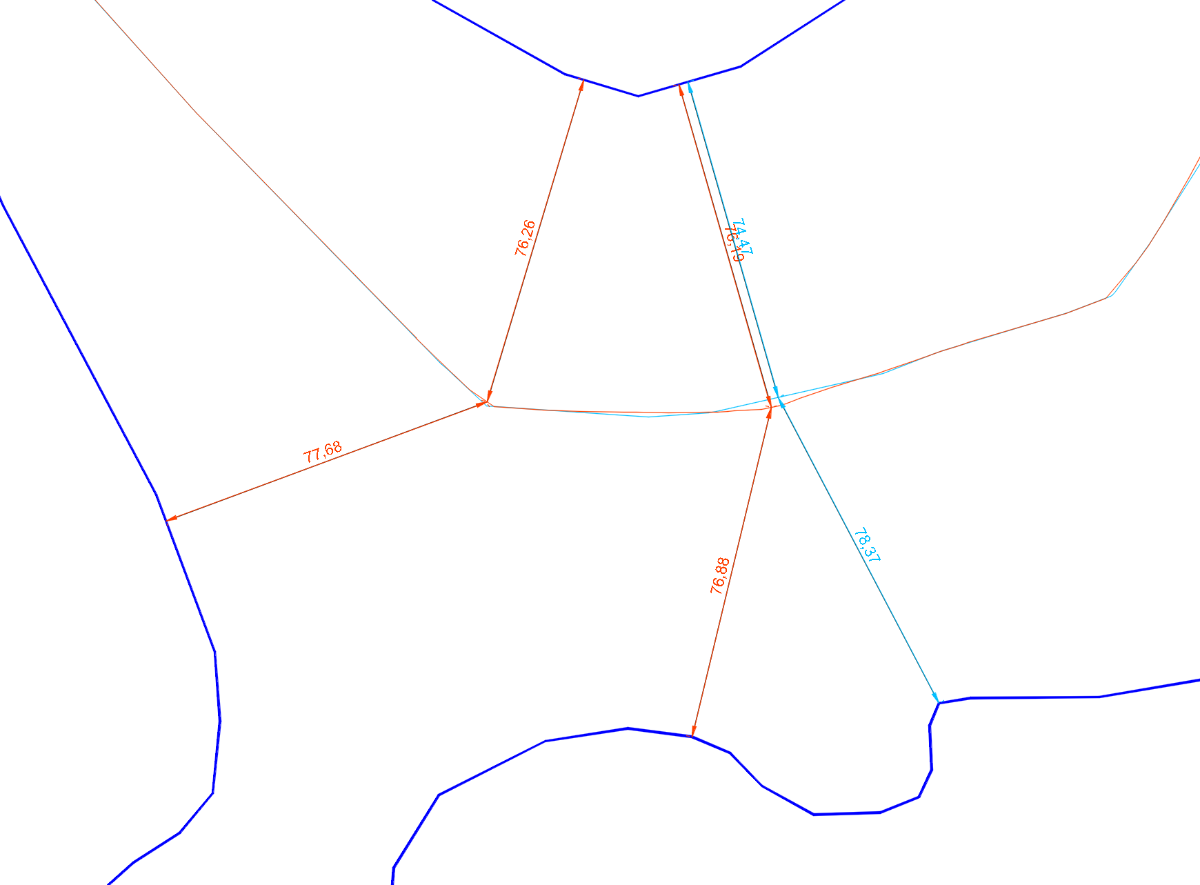
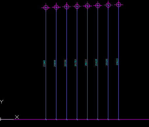
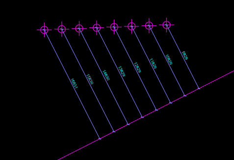
After being too busy working on my 2025 financial balance, I’ve had a bit of time to test the latest published codes. In addition, I found a new “toy” to test them with. To see the result in detail, you can download the attached drawing. Another.dwg In the images I show some examples of what I have observed: There are still some significant errors in the equidistance of the centerline. The latest code by glavcvs seems to always achieve equidistance at all points. However, inside some segments there are errors of more than 1 meter. I assume this is an issue that glavcvs has already solved but apparently has not yet published. The code by dexus has similar problems, but in addition there are also some points with significant errors in equidistance. Finally, I have also noticed that the latest code by glavcvs does not work on some of the drawings attached as examples in this thread. I suppose we are going very far— further than what was initially intended. For most people who come across this, this will probably be sufficient. But “immortality is always a little further ahead.” Many thanks to everyone who has participated in this so far and to those who will do so in the future!

-

LISP for Dimensioning from Multiple Points to Line
pkenewell replied to comet712's topic in AutoLISP, Visual LISP & DCL
Here is a boiled down simple version with no error testing. It assumes that the dimensions will run on the same angle as the angle between the point and the curve segment: ;; Created by P. Kenewell 1/22/2026 (defun c:dim2pts (/ ep i p1 p2 p3 ss) (if (and (progn (princ "\nSelect Points to Dimension: ") (setq ss (ssget '((0 . "POINT")))) ) (setq ep (entsel "\nSelect a curve to Dimension to: ")) ) (repeat (setq i (sslength ss)) (setq p1 (cdr (assoc 10 (entget (ssname ss (setq i (1- i)))))) p2 (vlax-curve-getclosestpointto (vlax-ename->vla-object (car ep)) p1) p3 (polar p1 (angle p1 p2) (/ (distance p1 p2) 2)) ) (command "._dimrotated" (* (/ (angle p1 p2) pi) 180.0) "_non" p1 "_non" p2 "_non" p3) ) ) (princ) ) Example Screenshots:
- Today
-

LISP for Dimensioning from Multiple Points to Line
devitg replied to comet712's topic in AutoLISP, Visual LISP & DCL
@Kumar1 please make or send a real dwg , with points-layer, line-layer, dim-layer and a new dimstyle not an overrided style, so all variables system are stated . Like the first DWG posted at this topic Dimension from Point to line.dwg
-
 matt123 joined the community
 -

Repair Lisp to create superimpose acad
karfung replied to karfung's topic in AutoLISP, Visual LISP & DCL
@rlx Kindly assist to resolve this. Thanks. -
ptsalign should do it.
-

3D render in Paper Space jagged lines
Reetie Lubana replied to al_bey's topic in AutoCAD 3D Modelling & Rendering
This is a fairly common Paper Space / viewport issue rather than a problem with your model. What you’re seeing is facet aliasing caused by how AutoCAD displays and plots shaded viewports, especially when using the BASE command. Model Space looks fine because it’s using higher real-time display resolution; Paper Space viewports are rasterized differently. Here are the things that usually fix it: 1. Increase viewport display resolution AutoCAD uses a lower tessellation for shaded viewports by default. In Model Space, type: FACETRES Set it to: 10 (Valid range is 0.01–10, higher = smoother curved/diagonal edges) Then REGENALL. 2. Check VIEWRES Still in Model Space: VIEWRES Answer Yes to fast zooms Set it to something like: 2000 This affects how smooth diagonal edges appear when displayed. 3. Viewport Visual Style In Paper Space, select the viewport and confirm: Visual Style = Shaded or Shaded with Edges Not Conceptual or Realistic (those can exaggerate faceting) You can also try: SHADEDGE Set to: 3 (Smooth edges without heavy outlines) 4. Plot settings (very important) When plotting to PDF: Plotter: DWG To PDF.pc3 In Properties → Graphics: Set Vector Resolution to 1200 dpi Set Raster Image Quality to High Make sure Plot transparency is ON (even if you’re not using transparency) Low raster resolution is a major cause of jagged diagonal shading. 5. BASE command note The BASE command creates a Paper Space representation that behaves like a shaded viewport. It’s more sensitive to resolution than raw Model Space views. Increasing FACETRES and plot resolution almost always fixes this. 6. Quick test As a sanity check: Create a normal viewport (not BASE) Set it to the same view and visual style Plot it If the jagged edges disappear, the issue is 100% display/plot resolution related, not geometry. -

LISP for Dimensioning from Multiple Points to Line
Kumar1 replied to comet712's topic in AutoLISP, Visual LISP & DCL
this lisp is fine, but instead of picking each point, can we write a lisp routine to select multiple points and write dimension automatically. Sample File uploaded above. -
LISP for Dimensioning from Multiple Points to Line
Kumar1 replied to comet712's topic in AutoLISP, Visual LISP & DCL
this lisp is fine, but instead of picking each point, can we write a lisp routine to select multiple points and write dimension automatically. -
LISP for Dimensioning from Multiple Points to Line
Kumar1 replied to comet712's topic in AutoLISP, Visual LISP & DCL
AutoDimensioning-VV.dwg -
I've included another video as an example. smart offset.mp4
-
 Cristian joined the community
 -
Thank you for your answers. The Lisp code you described might be useful, but as you said, when traversing areas like walls or columns, it offsets the line by 6 units, and if there's a pre-drawn, offset line, it follows it all the way to the end. Could you share your code? @BÜYÜK
-
 snowman.hms joined the community
 - Yesterday
-
I did something for water pipes or electric cables in a road, it just allows you to follow line segments, with a predefined offset. I am not sure though in your last bit of Video if you want to enter the length of the last leg, can you clarify that. The code I have draws a full last length. @ScottMC not sure that overall length is required. Just a ps did you mean to post the actual code as you have the lisp file to download.
-
Here's a useful Lee.Mac Power.tool TotalLengthPolylineV1-0.lsp
-
Hi, I need a smart and dynamic offset Lisp when drawing electrical projects. polyline will follow the wall. Like in the video. ScreenRecording_01-20-2026 22-20-40_1.mov
-
 hardwell3458 joined the community
 -
LISP for Dimensioning from Multiple Points to Line
devitg replied to comet712's topic in AutoLISP, Visual LISP & DCL
@Kumar1 please upload a sample.dwg with, at least, 2 o3 dim as you need it to be -
Very nice @CyberAngel, like it!
-
Why get fancy? (max 0 (- botLength 6000))
-

Multileader justify paragraph doesn't work
CyberAngel replied to 3dwannab's topic in AutoCAD Bugs, Error Messages & Quirks
I've had this problem for a long time. To apply justification to text in a multitext, you have to select it. Even if the justification applies to the entire contents. That doesn't match what happens in word processors, but whatevs. -
а как запустить команду?
-
 гена joined the community
 -
Kumar1 joined the community
-
LISP for Dimensioning from Multiple Points to Line
Kumar1 replied to comet712's topic in AutoLISP, Visual LISP & DCL
auto dimensioning by selecting multiple points and one line object -
(if (minusp (- botLength 6000)) (setq botLength 6000) )
-
 Tajammal joined the community
 -
Just another example, nice, also it would work.
-
If (- botLength 6000) is minus.... (if (= (minusp (- botlength 6000)) T) ;; verifies that a number is negative (setq botLength 0) ;; if it is, it will set to 0 (setq botLength (- botLength 6000)) ;; if it isn't, it will be substracted with "6000" ) ;;End If
-
(if (= (minusp botLength) T) ;; verifies that a number is negative (setq botLength 0) ;; if it is, it will set to 0 (setq botLength (- botLength 6000)) ;; if it isn't, it will be substracted with "6000" )
-
You mean like this? (if (minusp botLength) 0 (- botLength 6000))