All Activity
- Today
-
Calculating an axis using angle bisectors a) Attempt number 1 (it was my first impulse, but I came up with a better one later) Advantages: - Pure LISP: doesn't depend on Express Tools, - It's faster Disadvantages: - The result isn't as good as @GP_'s "c:CPL" - It only accepts LWPOLYLINES and ignores arcs Basically, the approach is to obtain angle bisectors on each polyline, extend them to the other reference polyline, and use their midpoints. The result is acceptably good, but not as accurate as c:CPL. (defun c:creAxis (/ e e1 e2 l1 l2 lr p p0 p1 p2 px pm abis lii pmi pfi pi1 pi2 pf1 pf2 dameInters+Prox ordena) (defun dameInters+Prox (p0 a lp / p1 px pt1 pt2 dmin d pf) (setq pt1 (polar p0 a 1e8) pt2 (polar p0 (+ a PI) 1e8)) (foreach p lp (if p1 (if (setq px (inters pt1 pt2 p1 p)) (if dmin (if (< (setq d (distance px p0)) dmin) (setq dmin d pf px)) (setq dmin (distance px p0) pf px)) ) ) (setq p1 p) ) pf ) (defun ordena (pr lp / d dmin ps lr) (while lp (foreach p lp (if dmin (if (< (setq d (distance p pr)) dmin) (setq dmin d ps p) ) (setq dmin (distance p pr) ps p) ) ) (setq dmin nil pr ps lp (vl-remove ps lp) lr (append lr (list ps))) ) ) (if (and (setq e1 (car (entsel "\nSelect first LWPOLYLINE..."))) (= (cdr (assoc 0 (setq l1 (entget e1)))) "LWPOLYLINE") (not (redraw e1 3))) (if (and (setq e2 (car (entsel "\nSelect second LWPOLYLINE..."))) (= (cdr (assoc 0 (setq l2 (entget e2)))) "LWPOLYLINE") (not (redraw e2 3))) (progn (setq lp1 (reverse (foreach l l1 (if (= (car l) 10) (setq lr (cons (cdr l) lr)) lr))) lr nil; lp2 (reverse (foreach l l2 (if (= (car l) 10) (setq lr (cons (cdr l) lr)) lr))) lr nil; ) (if (< (distance (setq pi1 (cdr (assoc 10 l1))) (setq pi2 (cdr (assoc 10 l2)))) (distance pi1 (setq pf2 (cdr (assoc 10 (reverse l2)))))) (setq pmi (mapcar '(lambda (a b) (/ (+ a b) 2.0)) pi1 pi2) pfi (mapcar '(lambda (a b) (/ (+ a b) 2.0)) (setq pf1 (cdr (assoc 10 (reverse l1)))) pf2) ) (setq pmi (mapcar '(lambda (a b) (/ (+ a b) 2.0)) pi1 pf2) pfi (mapcar '(lambda (a b) (/ (+ a b) 2.0)) (cdr (assoc 10 (reverse l1))) pi2) ) ) (redraw e1 4) (redraw e2 4) (foreach l l1 (if (= (car l) 10) (if p1 (if p2 (setq abis (+ (/ (+ (angle p1 p2) (angle p2 (cdr l))) 2) (/ PI 2.)) x (princ) px (dameInters+Prox p2 abis lp2) lr nil pm (if px (mapcar '(lambda (a b) (/ (+ a b) 2.0)) p2 px)) lii (if px (append lii (list pm)) lii) p1 p2 p2 (cdr l) ) (setq p2 (cdr l)) ) (setq p1 (cdr l)) ) ) ) (setq p1 nil p2 nil lr nil) (foreach l l2 (if (= (car l) 10) (if p1 (if p2 (setq abis (+ (/ (+ (angle p1 p2) (angle p2 (cdr l))) 2.) (/ PI 2.)) px (dameInters+Prox p2 abis lp1); pm (if px (mapcar '(lambda (a b) (/ (+ a b) 2.0)) p2 px) (princ) ) lii (if px (append lii (list pm)) lii); p1 p2 p2 (cdr l) ) (setq p2 (cdr l)) ) (setq p1 (cdr l)) ) ) ) (setq lii (append (list pmi) (ordena pmi lii) (list pfi))) ) ) ) (entmake (append '((0 . "LWPOLYLINE") (100 . "AcDbEntity") (67 . 0) (8 . "0") (100 . "AcDbPolyline") (70 . 0) (60 . 0)) (list (cons 90 (length lii))) (mapcar '(lambda (a) (cons 10 a)) lii))) (princ) ) PS: It seems to work well, but I haven't tested it extensively. As I said at the beginning, there's a better approach, using angle bisectors, which I'll publish later.
-
If I get any time at home, I'll do some testing in AutoCAD 2000i.
-

Lisp request... trim (wall) lines with (column) multiple closed plines and circles
SLW210 replied to ilarch2016's topic in AutoLISP, Visual LISP & DCL
Try mine... -
There may be different versions at the Swamp as well. John Uhden has a few versions.
-

Lisp for to get y value of polyline based on datum value and line.
Saxlle replied to Ish's topic in AutoLISP, Visual LISP & DCL
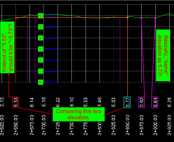
@symoin Can you please explain the logic of getting an elevation from "Profile-sample.dwg"? It is kind different from the picture which were you posted above. If I am not getting wrong, from picture below, the elevation need to looks like this (so, the equidistant need to be equal?): Best regards.
-

Lisp request... trim (wall) lines with (column) multiple closed plines and circles
ilarch2016 posted a topic in AutoLISP, Visual LISP & DCL
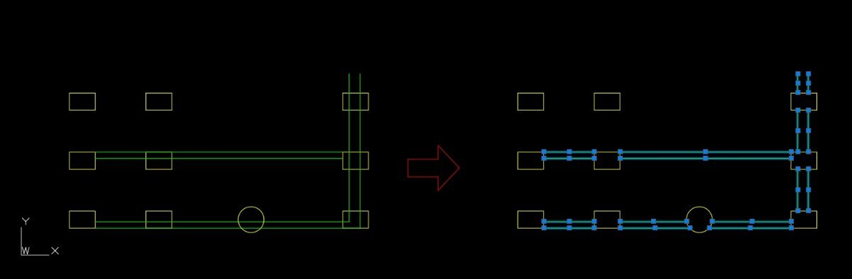
HI~there First of all, thank you to anyone willing to help me. I need a LISP routine. Command name: CCW (Column Cut Wall) The workflow is: first select the yellow layer (columns), then select the green layer (walls). The routine should trim all wall lines that are inside the closed polylines on the column layer, including cutting and removing any wall lines that overlap with the column boundaries. lisp request.dwg
-
I know of and have previously tried StripMtext V5.0c which didn't remove the height override. Some additional searching and the second version of v5.0d I found does remove the height override! Located here, message 54 - Solved: strip mtext formatting - Page 3 - Autodesk Community Previously the version from John Uhden removed my stacking formatting which I wanted to keep. Thanks for your help!
- Yesterday
-

Lisp for to get y value of polyline based on datum value and line.
symoin replied to Ish's topic in AutoLISP, Visual LISP & DCL
Here is the profile sample PROFILE-SAMPLE.dwg -
 Takk joined the community
 -
It's true... sorry I'm curious to see if there are any differences.
-
Yes, I added (acet-load-expresstools) Answered by me. Gian's (as well as the other LISPs) still want to cut some corners short, etc. IMHO. @mhupp's actually does some of the corners better, though "off" in other places. I believe Civil 3D has something to do this, but it may not be much better. If I get more time I'm still going to work on improving mine.
-
Normally the final result is a polyline, maybe you don't have ExpressTools loaded, try: (or acet-flatn (load "FLATTENSUP.LSP"))
-

Looking for a LISP to evenly space polylines from their end points
Tamim posted a topic in AutoLISP, Visual LISP & DCL
HI, I’m working on a CAD drawing that has several parallel polylines, and I’d like to space them out evenly by a fixed distance, but only from their start points. For example, all the lines begin from point No. 1, and I want to distribute only between line 1 and line 2, keeping the rest aligned. The goal is to spread them equally on the opposite side, similar to how the “Distribute” option works in TEXTALIGN, but for polylines instead of text. It would be great if the spacing value (for example, 0.2 ft or 0.5 ft) could be entered by the user. Does anyone know if there’s an existing LISP routine for this, or something close? Any tips or examples would be really helpful. line shifting.dwg -

3 Ways to Get Back! AutoCAD REVERT, UNDO, and OOPS: Tuesday Tips With Frank
The AutoCAD Blog posted a topic in AutoCAD Blogs
Today’s Tuesday Tip is really three tips in one, with all three sharing the same theme. They let you Get Back to where you… started (you thought I was going to say once belonged, didn’t you?) Sometimes our work doesn’t take us where we want, and we realize it’s best to start over, or as the Fab Four told us, it’s time to Get Back. AutoCAD REVERT: Toss It and Start Over The scenario: You have an existing drawing, and its design needs to be updated. There are various design options, and your job is to try them and decide on the best. You work for a while, try ideas, get stuck, get unstuck, work more, until you realize it’s just not going to work. Yes, you could close the drawing, making sure that you don’t save it, then reopen it to start over. There are better options that will get you there quicker. The first is an Express Tool. It is called REVERT, and it does exactly what you might think. It tosses out all your edits and Gets Back to the state of the drawing when you opened it. It’s not in the Ribbon, so you’ll have to remember its name – unless you have the MENUBAR turned on. I first wrote about the Express Tools found in the MENUBAR way back in 2018. There are more tools there than in the Ribbon. You can find REVERT there if you want. There’s another way to revert your drawing back to its original state, and it works as a segue into my next topic. You can type in the full UNDO command, then B for Back, then accept the Y for Yes to accept the prompt to undo everything. AutoCAD UNDO: Control Your Undo Some of you may not be aware that UNDO is a full-fledged command with options. If you’re like most of us, you type U and pop the spacebar, or maybe use the Windows Ctrl-Z option or the little icon (and pulldown menu) in the QAT. Let’s consider our design scenario again. This time, some of your initial design changes work perfectly, and you don’t want to lose them if you continue. In other words, a full REVERT or UNDO “Back” later on would remove things that you want to keep. But UNDO is still your friend here. Notice all the options available in the full command. I’ll be focusing here on one of them, but feel free to explore further in the help file. You can use the “Mark” option to set a kind of bookmark of the current state of your drawing. You can set multiple, in fact. Later, when you do an UNDO “Back”, it will only go back until it finds the most recent Mark. Once a Mark is encountered, it will be removed. If you have more than one Mark set, subsequent calls to UNDO “Back” will go to those. If you’re using the U <enter> method (which is actually UNDO <1>) and a Mark is encountered, you will be informed about it. Once all of your Marks are accessed and removed, running UNDO will Get Back to the beginning. AutoCAD OOPS: Get Back the Erased Back to our design scenario one more time. You work on an idea, get to the end, and decide against it, so you erase it all. You work on a different part of the design for a while, which is going to work great, but then you realize the stuff you deleted would now work in conjunction with your new design. You want to keep what you have, but also Get Back what you’ve deleted. Now what? That’s where our last option comes in handy. It’s called OOPS. Yes, I’m serious here. As far as I know, it’s been in AutoCAD from the very beginning. It restores the last object, or set of objects, that were deleted by the last ERASE command. Just type it into the command line and press return, and your object or objects will return. A word of warning, though, OOPS doesn’t work like UNDO does. It won’t keep going back in time restoring erasures. It’s a one-time deal. You can only Get Back the last object or objects that were erased. And In the End… I’ve got to hand it to myself. It was so tempting to fill this post with Beatles puns, but I was able to stick to the topic. Using REVERT, UNDO, and OOPS, you can easily Get Back the last thing you erased, you can Get Back to a virtual bookmark in your design, or you can Get Back to where you started. And now, I’ve Got a Feeling that I’m going to call my dog, Jo Jo over, we’ll Come Together, and I’ll drop all my pent-up puns on him. It will be just the… Two of Us. More Tuesday Tips Check out our whole Tuesday Tips series for ideas on how to make AutoCAD work for you. The post 3 Ways to Get Back! AutoCAD REVERT, UNDO, and OOPS: Tuesday Tips With Frank appeared first on AutoCAD Blog. View the full article -
Yes I already said my method wasn't perfect. That's why, besides Lisp, I wanted to know if there was a better method than mine. And the result GP_'s Lisp achieves corresponds very well with what I understand to be a correct axis. The only drawback might be using this code in AutoCAD 2000. But I suppose I can avoid that in AutoCAD 2015.
-

How to show inch marks ( double quote ) after a decimal dimension?
mhupp replied to ILoveMadoka's topic in SolidWorks
100% agree. I'd take BIGAL's route but idk if it would suffer from the same issue as my first screenshot. but the macro could be used to update old drawings easily. Coming from cad one of my main grips about solidworks was the customization and how you had to go digging around menus to change things. But I inderstand why it's that way. Did see if you had a dimension selected in the option panel you could go to other tab > override > feet inch and it would use like 3' - 6“ but if it was less than 12" it would only use in. Our drawings only show the number and just have a note in the title block saying. all dimensions are in inches unless otherwise called out. We have some Europe contracts so we will have to do things in metric from time to time. -

Impossible to change attribute text size within dynamic block
jamami replied to jamami's topic in AutoCAD Drawing Management & Output
hi again.... i see this offers a solution to update attributes within nested blocks, however my issue is that i need to change the size of the text depending on what scale i intend to show at. I had foolishly assumed that defining a unique text style would give this control, but this doesn't work as when defining attributes a size needs to be specified. -
Impossible to change attribute text size within dynamic block
SLW210 replied to jamami's topic in AutoCAD Drawing Management & Output
It seems you posted this here as well... Attribute text size not changing in dynamic block - Autodesk Community You need to run ATTSYNC on the block, but, how you made the block, when trying to use ATTSYNC it reports the block has NO ATTRIBUTES. You added the visibility states into the block as nested Items, easy solution is to update the nested blocks with LISP. Maybe... Solved: Update attributes of nested blocks in dynamic blocks - Autodesk Community -
Yes, GP_'s need Express Tools AFAIK. As I posted, It still is off from yours on some corners. It also creates lines and splines, though easy enough to make them polylines.
-
How to show inch marks ( double quote ) after a decimal dimension?
SLW210 replied to ILoveMadoka's topic in SolidWorks
Still a lot of work for what should be easy and already available. When I used Solidworks I was mostly lucky in using either Metric or Architectural with fractions. I would have done some for the machine shop in Decimal inches, IIRC, I added the (" ) in AutoCAD when I made the detail drawing. -
I haven't looked at @Lee Mac's, but I use this one. There may be newer than version 5.0 at the Swamp or here. Allows selecting what to remove. Solved: strip mtext formatting - Autodesk Community More reading and information from John Uhden, I also use his versions, the original lets you select what to remove, which may be in one of the threads. Re: StripMText Issue - Autodesk Community
-
.thumb.jpg.3b78dfd98016b6a62fa0f34b5cf003ea.jpg) Isabela joined the community
Isabela joined the community -
 mr_fiftik joined the community
 -

Python, Extract Polyline Lengths with Associated Text Labels in AutoCAD
Danielm103 replied to Danielm103's topic in .NET, ObjectARX & VBA
see https://github.com/CEXT-Dan/PyRx -
Lisp for to get y value of polyline based on datum value and line.
Saxlle replied to Ish's topic in AutoLISP, Visual LISP & DCL
Can you provide the an example drawing? I'm not familiar with working in Civil 3D. -
Extract Polyline Lengths with Associated Text Labels in AutoCAD
Saxlle replied to Tamim's topic in AutoLISP, Visual LISP & DCL
The reason is: "no polylines are selected, so the Lengths of the polyline were not obtained". As I can see in the another file example, it's different from the original "Line Length Sample", so the code will not work as expected. I agree with @Danielm103 wath he said (standardized label = height, position below/above polyline, etc.). -
@GLAVCVSthanks
-
How to work with closed drawing(s) in Python (ObjectDBX)
Danielm103 replied to Danielm103's topic in .NET, ObjectARX & VBA
Working with the layout manager in a side database context, LayoutManager methods have overloads that take a database argument import traceback from pyrx import Db, Ed, Ge, Ap, Rx, Gs from timeit import default_timer as timer from collections import defaultdict def processDWG(db: Db.Database, allLayouts: dict[list]): lm = Db.LayoutManager() # LayoutManager methods have overloads that take a database argument # here we just want to get the layout names for layoutName, LayoutId in lm.getLayouts(db).items(): allLayouts[db.getFilename()].append(layoutName) # example if we want to search for title blocks # ignore the model tab if not "MODEL".casefold() in layoutName.casefold(): layout = Db.Layout(LayoutId) ps = Db.BlockTableRecord(layout.getBlockTableRecordId()) for id in ps.objectIds(Db.BlockReference.desc()): ref = Db.BlockReference(id) print(ref.getBlockName()) def readDWG(file: str, allLayouts): sideDb = Db.Database(False, True) sideDb.readDwgFile(file) sideDb.closeInput(True) processDWG(sideDb, allLayouts) @Ap.Command() def doit(): try: start = timer() allLayouts = defaultdict(list) for file in Ap.Application.listFilesInPath("E:\\temp", ".dwg"): readDWG(file, allLayouts) print("Time = {} seconds: ".format(timer() - start)) for k, v in allLayouts.items(): print(k, v) except Exception as err: traceback.print_exception(err) Command: DOIT Project data <--- a block I added to paperspace, could be a title block Time = 0.0780531999989762 seconds: E:\temp\Floor Plan Sample1.dwg ['Layout1', 'Model'] E:\temp\Floor Plan Sample2.dwg ['Layout1', 'Model'] E:\temp\Floor Plan Sample3.dwg ['Layout1', 'Model'] E:\temp\Floor Plan Sample4.dwg ['Layout1', 'Model'] E:\temp\Floor Plan Sample5.dwg ['Layout1', 'Model'] E:\temp\Floor Plan Sample6.dwg ['Layout1', 'Model'] E:\temp\Floor Plan Sample7.dwg ['Layout1', 'Model'] E:\temp\Floor Plan Sample8.dwg ['Layout1', 'Layout2', 'Model']