Search the Community
Showing results for tags 'dimension'.
-

How to show inch marks ( double quote ) after a decimal dimension?
ILoveMadoka posted a topic in SolidWorks
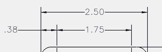
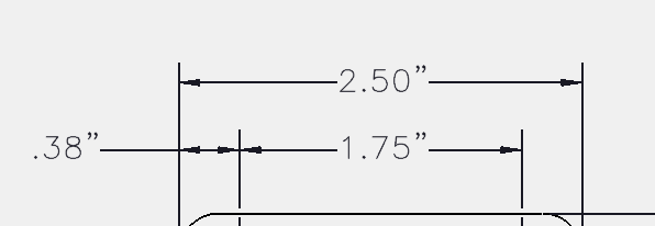
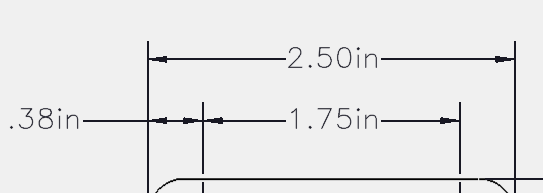
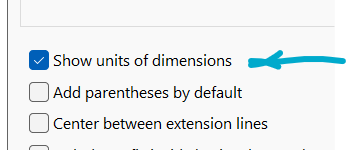
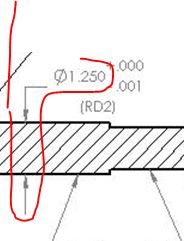
Solidworks 2023 How can I show inch marks after a decimal dimension? these are "hand-jammed" The closest I could figure out without having to manually change every dimension gave me this Is this possible? Help please..
-

dimension Change Qleader Setting via Command Line
reza posted a topic in AutoLISP, Visual LISP & DCL
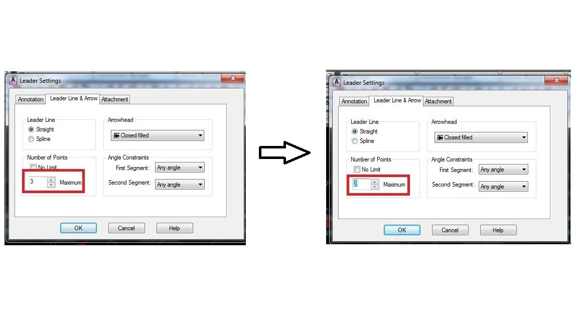
Hi everyone When I open a dwg file and use the attached lisp to change the Qleader settings, no changes are made to the settings. Please fix the problem for me. qlset.lsp.lsp test.dwg
-

inputting imperial units
mgervais posted a topic in AutoCAD 2D Drafting, Object Properties & Interface
Im having trouble inputting imperial units for my line lengths. It works fine when i type 4-3/4 it gives me a line that is 4 and 3/4 of an inch long. Can i only input values in inches or is it possible to input something say 4' 4-3/4 ?? Thanks -

Create field from attribute in block and put it directly into dimension.
fromMlm posted a topic in AutoLISP, Visual LISP & DCL
Hi all, Again I have found a lisp Lee Mac made that copies a field into a dimension, "copyfield", but it requires that the field already exists... So is there a way to create a field from an attribute in a block and then insert the field directly into a dimension? Thanks in advance. -

How to get dimension Start point & End point of arrow head
Pugazh posted a topic in AutoLISP, Visual LISP & DCL
hello dears, I want to make line in multiple dimension using start point & end point of dimension. (defun c:makeline ( ) (setq ss (ssget "_:L" '((0 . "DIMENSION")))) (repeat (setq i (sslength ss)) (setq ent (ssname ss (setq i (1- i)))) (command "_.line" "_non" (cdr (assoc 10 (entget ent))) "_non" (cdr (assoc 11 (entget ent))) "") ) (princ) ) -

Dimension’s extend line is overlap with others
haisagiviz posted a topic in AutoLISP, Visual LISP & DCL
Hi everyone, My question: Is there anyway to detect dimension's node when node’s distance from dimension line are greater than a number and move them back to dimension base line. My problem: the dimension's extend line is overlap with other line such as grid line, wall line and others. Regards. -

Aligned Dimensions from a line to a perpendicular line, with centered text.
Jean-Lévy Plante posted a topic in AutoLISP, Visual LISP & DCL
I would like to modify this lisp script so that the dimension has a centered text instead of on a side of the dimension. But i don't know how. (defun c:HD (/ HD_LineHouse HD_LineProperty HD_Point1 HD_BasePoint1 HD_Text1 HD_Point2 HD_BasePoint2 HD_Text2 HD_ActiveDoc HD_ActiveSpace) (if (and (setq HD_LineHouse (car (entsel "\nSelect house line : "))) (setq HD_LineProperty (car (entsel "\nSelect property boundary: "))) (= (vla-get-ObjectName (setq HD_LineHouse (vlax-ename->vla-object HD_LineHouse))) "AcDbLine") ) (progn (setq HD_LineProperty (vlax-ename->vla-object HD_LineProperty)) (if (not (vl-catch-all-error-p (setq HD_Point1 (vl-catch-all-apply 'vlax-curve-getClosestPointTo (list HD_LineProperty (setq HD_BasePoint1 (vlax-safearray->list (vlax-variant-value (vla-get-StartPoint HD_LineHouse))))))))) (progn (setq HD_Point2 (vlax-curve-getClosestPointTo HD_LineProperty (setq HD_BasePoint2 (vlax-safearray->list (vlax-variant-value (vla-get-EndPoint HD_LineHouse)))))) (setq HD_Text1 (polar HD_Point1 (angle HD_BasePoint1 HD_Point1) 0)) (setq HD_Text2 (polar HD_Point2 (angle HD_BasePoint2 HD_Point2) 0)) (vla-StartUndoMark (setq HD_ActiveDoc (vla-get-ActiveDocument (vlax-get-acad-object)))) (vla-put-TextPosition (vla-AddDimAligned (setq HD_ActiveSpace (vla-get-Block (vla-get-ActiveLayout HD_ActiveDoc))) (vlax-3d-point HD_BasePoint1) (vlax-3d-point HD_Point1) (vlax-3d-point HD_Point1)) (vlax-3d-point HD_Text1)) (vla-put-TextPosition (vla-AddDimAligned HD_ActiveSpace (vlax-3d-point HD_BasePoint2) (vlax-3d-point HD_Point2) (vlax-3d-point HD_Point2)) (vlax-3d-point HD_Text2)) (vla-EndUndoMark HD_ActiveDoc) (mapcar 'vlax-release-object (list HD_ActiveSpace HD_ActiveDoc)) ) ) ) ) (princ) ) HD-Automatic Dimension.LSP -
I thought it would be interesting to get a thread going about your favorite lisp. As I've been frequenting this forum, my list of lisps is ever-growing. I have some I think are excellent for what I do (steel detailer) but I wonder what is your favorite lisp? Maybe post here with a brief description and what you do? I always wonder if I may be just ultra lazy or if I just like to see how fast I can get s#!t done! Mine would be one of the most recent. This dimension lisp allows you to enter a dim and afterward changes it to a "?" and envokes the revcloud function and then returns you to your previous layer. I have multiple copies of this for different uses/layers/dimstyles/dimangular. In my work, this has become a huge time saver! Big thanks to "lamensterms" for helping me out with it. -Nobull (DEFUN C:D1 () (command ".dimstyle" "R" "YOUR DIMSTYLE HERE") (setq LAYOR (getvar "CLAYER")) (COMMAND "CLAYER" "YOUR LAYER HERE") (setq ocmd (getvar "CMDECHO")) (setvar "cmdecho" 1) (command "dimlinear" pause pause pause) (setvar "cmdecho" 0) (command "dimedit" "n" "?" "L" "") (setvar "CMDECHO" ocmd) (COMMAND "CLAYER" "YOUR LAYER HERE") (setq p1(getpoint "\nPick first corner of window: ")) (setq p2(getcorner p1 "\nOpposite corner: ")) (setvar "plinewid" 0) (command "rectang" p1 p2) (command "REVCLOUD" "O" (entlast) "N") (setvar "CLAYER" LAYOR) (PRINC) )
-
Hi All, I have an issue about dimension scaling and any tips on how to make them even in paper space so it looks clean and symmetrical for architects to read. There are some drawings i use in MVIEW that are so large that the dimension texts are small. And some that are small that are easily readable. How do i distribute all the dimension font to be even in Paperspace? Any tips are appreciated. Thanks!
-
Hello All, I am working on making Bills of Materials with Block information. I use tubing as a main component in my data extractions. What I would like to do is be able to extract the text overwritten length that I dictate from the all dimension leaders with the same part number, and add them to get an overall length of tubing used in the assembly. For instance if I have two blocks, both with the part number "tube 1" but one has a dimension leader where I overwrite 5 (inches) and one has a dimension leader where I overwrite 6 I would like the data extraction to show "tube 1" with 11 (inches). Much appreciated!
-

LISP - Automatic dimensions according to set rules
Kyler posted a topic in AutoLISP, Visual LISP & DCL
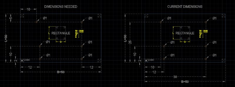
Hello everyone, I work with a glazing company and am trying to write an AutoLISP command that will automate a large part of our job by dimensioning glass panels with holes and cutout in the format that our supplier prefers. I will attach a photo here to show what I have done so far. The rectangle on the left shows what I would like the dimensions to look like. The rectangle on the right shows what my LISP routine currently does. I am having trouble writing the logic to dimension it in the way that I want. Rules it should follow are: 1) dimensions strings should be made to the corner nearest to the hole 2) if two holes are in-line, the dimension should pass through the closer hole 3) if two dimensions go to the same corner, they should stack at 3" intervals (TYP. offset set for DIMBASELINE) 4) Dimension strings should always be 3" behind the larger dimension above them (See the 5" measure at the top left) However, these rules only hold true for the "rectangle" shape option. In the final version of the routine, I am looking to have an easily expandable list of rules that I can modify and tweak per-shape. I have attached a test drawing and the current version of my LISP routine below. The code for dimensioning rules on the rectangle is found on lines 436-494. Any help figuring this out would be much appreciated. Thank you! Drawing File: autodimtest.dwg Current LISP: autoDim.lsp
-
Hello all, I wondered if it's possible to have a kind of command or lisp that gets the continue and baseline command in one single command? In the picture below you see the result I need in one command. Now it is done in 2 commands and it's taking a lot of time. Can somebody help me? Thanks! Kind regards, Martin
-
Hello, Could anyone help me let this LISP work. The lisp should go to the layer you choose (by pressing 1 or 2) when in a *DIM* command. After placing the dimension the layer should go back to the layer it was before selecting a *DIM* command. This is the code now. ; AFKORTINGEN VAN DE VARIABELEN ; ADDL Automatic dimension layer ;**************************************************************************** (defun CommandReactor:Start () (or *CommandReactor* (setq *CommandReactor* (vlr-command-reactor nil '( (:vlr-commandcancelled . CommandReactor:CommandEnded) (:vlr-commandended . CommandReactor:CommandEnded) (:vlr-commandfailed . CommandReactor:CommandEnded) (:vlr-commandwillstart . CommandReactor:CommandWillStart) ) ) ) ) (prompt "\nCommand reactor loaded. ") (princ) ) ;**************************************************************************** (defun CommandReactor:CommandEnded (rea cmd) (if (and *OldClayer* (wcmatch (strcase (car cmd)) "*DIM*") ) (progn (setvar 'clayer *OldClayer*) (setq *OldClayer* nil) ) ) ) ;**************************************************************************** (defun CommandReactor:CommandWillStart (rea cmd) (if (wcmatch (strcase (car cmd)) "*DIM*") (progn (setq *OldClayer* (getvar 'clayer)) (vla-add (vla-get-layers (vla-get-activedocument (vlax-get-acad-object))) ; Kiezen van de DIM layer (setq ADDL 0) (while (or (< ADDL 1) (> ADDL 2)) (setq ADDL (getint "\nInput the DIM layer: Dim. (1), Dim. front (2): "))) ) ; end while ;ADDL = 1, Dimension layer (if (= ADDL 1) (progn (command "_layer" "_m" "S-DIMENSIONS" "_c" "3" "" "") ); progn ); if (=ADDL 1) ;ADDL = 2, Dimension front layer (if (= ADDL 2) (progn (command "_layer" "_m" "S-DIMENSIONS front" "_c" "3" "" "") ); progn ); if (=ADDL 2) (setvar 'clayer *OldClayer*) ) ) ) ;**************************************************************************** (CommandReactor:Start) (princ) ;**************************************************************************** ;**************************************************************************** ;**************************************************************************** ;**************************************************************************** Please help! Thanks!
-

LISP script to perform Ordinate Dimension verification
Matt_D posted a topic in AutoLISP, Visual LISP & DCL
Hi All. This is my second attempt to post this since somehow I was logged out automatically. Thankfully I had most of this saved via a notepad file. Now down to business: I'm good with CAD, but when it comes to LISP, i'm a complete beginner. My boss/manager has asked me to create a LISP routine that will be run with a command from the command line and will receive user input to compare to ordinate dimensions within the drawing. I've been on this for two days, trying to wrap my head around even the basics and I can tell you my brain hurts. Programming of any sort is not my forte, i'm still struggling with getting HTML down. Anyways, the reason why my boss would like this is because sometimes our drawings have from a dozen to 50 or so ordinate dimensions and it's tedious to go and check them all against a point. My boss has given me free reign on how to design this sucker, but I'm stumped at how to program it as I'm a newbie. Below is what the lisp routine should be able to accomplish. The idea for the LISP is this: 1.) Load the lisp up and have it start with a defun C: command. 2.) have the user pick an 'origin' point for comparison (because we don't always use 0,0,0). 3.) the lisp takes this point and stores it. 4.) It scans the drawing for Ordinate Dimensions only. 5.) It compares the origin point of the user to the origin point of the ordinate dimensions. (I figure this would be the endpoint closest to 0,0,0. So for instance, if we have 15 dimensions, there are 30 endpoints. The 15 closest endpoints would be the ones that are compared to the origin point of the user.) 6.) It creates a new layer called DIM_WRONG [or whatever] and makes the layer RED. 7.) It draws attention to the incorrect ordinate dimensions (the ones scanned and compared to the user's origin point) by drawing either a red box around the dimension or a rev cloud. these rev clouds are placed on the DIM_WRONG layer, with the layer set to not plot. This way we can easily check between 15 and 30 and more ordinate dimensions with a few clicks. There would be a tolerance in the comparison, up to 1/64 of an inch tolerance. If the ordering steps needs to be adjusted because of programming structure, so be it, it just needs to compare those ordinate dimensions with a user assigned origin point, entered by keyboard or mouse. Again, I'm a beginner with Lisp and I've been trying to get segments done and have been only able to get 4 of the easy ones done (from that list). I've never been good at programming with anything. Any help would be vastly appreciated and I thank you for any advice/knowledge that you can bestow. -
Couldn't find it in solidworks 2015, the guy is using an old version of solidworks in the book i'm reading from, searched google to find out that that option has been removed since SW2010 SP2.1 Why would they do that ? Is there any alternative or any other option that does something similar ? Off topic: I can't find "solidworks" in the list of "Current Autodesk Product" in the profile, why is that ?
-
Hello, I have made some object addon on a large outdoor festival plan made years ago. When I mesure some object I add, the mesure shown are'nt good. If a make a new object with the same dimension and I move it over the old one, the scale is match. I to fix those different scaling? Thank you.
-
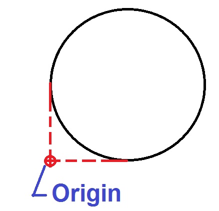
I need to set my origin a little different than inventor does it normaly. I have a circular plate and i want my origin on the intersection of tangents (low left corner) how do I do that.
-
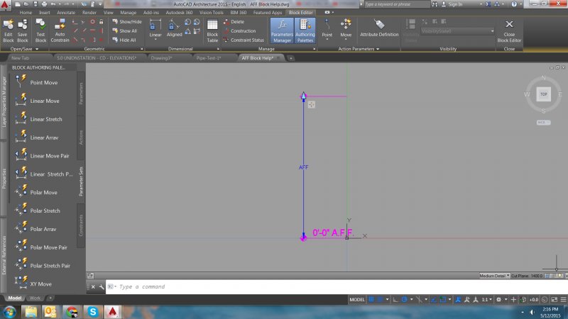
Hi all, I am trying to get the dimension of the AFF tag to automatically populate with the movement of the dynamic block. As it stands, I cannot get the "AFF" dynamic dimension through an attribute definition. I tried following Ellen's tutorial (here) but no luck. Help is much appreciated. AFF Block Help.dwg
-

Dimensions showing BOTH metric and imperial?
Sbeth85 posted a topic in AutoCAD 2D Drafting, Object Properties & Interface
Hi- I'd like to dimension a drawing in both feet and centimeters. Is there some sort of DimStyle workaround to get this to happen automatically? Yes, I know I could manually overwrite each dimension and do "inches", but is there a way to do it automatically? Thanks! -

dimension value fixing problem in simple lisp
anandhan posted a topic in AutoLISP, Visual LISP & DCL
(defun c:test () (setq obj (entsel "please select the dimension:-")) (setq ab (fix(getreal "please enter the value to change:-" ))) (command "dim1" "new" ab obj "") (princ) ) hi friends if i try to fix value more than 32600 it will fixed automatically some other value please help me what is the reason for this? -

dimension grip node stuck at arrow tip
rhgrafix posted a topic in AutoCAD 2D Drafting, Object Properties & Interface
I searched the universe and can't find this answer, Sometimes I find an existing dimension where one end has the node that has been collapsed to the tip of the arrow, I can't figure out how to pull it back off the arrow tip. I use 2011, any ideas? Thanks! R.L. Hamm -
I work in the HVAC field. I've just around a year of experience with the program and have never had this problem before. I use 2 layers; 1 for piping and another for linears and dimensions, etc. For some reason, everything shows up on the model space, but once i plotted on the paper space, a good chunk of the layer i use for my dimensions are not showing up at all. I've regenerated the drawing, checked the frozen/unfrozen state, made sure the layer was on, went through layer properties and my printer logo does appear without the red line through it. If anybody has any input or have experienced this problem before, anything would help because i'm stuck. Thanks
-

Programming on associative and nonassociative dimensions
Ahankhah posted a topic in AutoLISP, Visual LISP & DCL
Hi CADmates, I have drawings full of dimensions overlapping on each other. Should any one let me know how to get rid of this position via programming? I tried some coding to move text of dimensions, but no success on associative dimensions. ;| (MT:Move:DimensionText<-Ename (car (entsel)) nil 0 1 0) |; (defun MT:Move:DimensionText<-Ename (%ename% %absolute|relative% %x% %y% %z% / *entlist* *assoc11*) (setq *entlist* (entget %ename% '("*"))) (cond ((/= (cdr (assoc 0 *entlist*)) "DIMENSION") nil) (T (setq *assoc11* (cdr (assoc 11 *entlist*))); text position (setq *assoc11* (if %absolute|relative% (list %x% %y% %z%) (list (+ %x% (car *assoc11*)) (+ %y% (cadr *assoc11*)) (+ %z% (caddr *assoc11*))) ) ) (setq *entlist* (subst (cons 11 *assoc11*) (assoc 11 *entlist*) *entlist*)) (entmod *entlist*) ) ) ) I appreciate any help -

Very slow properties CAD on a decent machine
ColinPearson posted a topic in AutoCAD 2D Drafting, Object Properties & Interface
Hi all, I would appreciate any help I could get on this matter. I'm running CAD2011, a pretty good flavor of an i5, 8GB, Win7x64, 1GB graphics, etc... a nice-enough laptop for sure that CAD should be run seamlessly. HOWEVER! When I select a dimension, it takes at least 5 seconds for the properties box to correctly display and populate, then another few seconds once I click inside the box to be able to scroll/operate a drop down, type, etc. I have seen this posted with no resolution before... can anyone offer any advice on this matter? I saw one poster mention reloading support files such as fonts that may be corrupted but I must concede that I don't know exactly how to do this i.e, where would I get another copy of all of my fonts? -

Inventor 2014 Dimensions, what is it called? and where can i change it at?
Sengna posted a topic in Autodesk Inventor
I want to change my dimension arrows to something like below, what is it called? and where can i change it at? screenshot if possible please, thanks