All Activity
- Past hour
-
Options, Display, there is an item cross hair color, in Bricscad. Its X Axis color Y axis color. I run Black background so colors like red are good. No code required.
- Today
-
Untested I remember Lee Mac saying it was important to release the obj as it could cause a memory leak or something. the other commented out option will pop up the command prompt window for a split second and use the clip command. so if your cool with that its the better option as its only one line. ;;----------------------------------------------------------------------------;; ;; Copy Selected Xref Path to Clipboard with prompt. ;; https://www.cadtutor.net/forum/topic/98871-xref-path-copy-to-clipboard (defun c:XrefToClipBoard ( / SS Blk Path Obj Result) (vl-load-com) (if (setq SS (ssget "_+.:E:S" '((0 . "INSERT")))) (progn (setq Blk (vlax-ename->vla-object (ssname SS 0))) (setq Path "") (if (= (vla-get-isxref Blk) :vlax-true) (progn (setq Path (vla-get-path Blk)) ;(vlax-invoke (vlax-get-object "WScript.Shell") 'Run (strcat "cmd.exe /c echo " (vl-prin1-to-string Path) "| clip" ) 0 :vlax-true) ;This runs a command prompt (if (setq Obj (vlax-create-object "htmlfile")) (progn (setq Result (vlax-invoke (vlax-get (vlax-get Obj 'ParentWindow) 'ClipboardData) 'SetData "Text" Path)) (vlax-release-object Obj) ) ) (alert (strcat "\nCopied to Clipboard\n Xref Path: " Path)) ) (princ "\nSelected Block isn't an Xref.") ) ) (princ "\nNothing Selected") ) (princ) )
- 1 reply
-
- 2
-

-
Some food for thought - https://www.theswamp.org/index.php?topic=56816.msg605115#msg605115 To obtain the colour numbers, you can use my RGB<->OLE conversion functions: https://lee-mac.com/colourconversion.html#rgbole
-
I have a series of PDF sheets created from Revit. When I import a PDF sheet into Autocad, some sheets convert everything to autocad geometry while some other sheets only convert a few lines/text objects. The rest are raster images. What setting(s) controls whether a PDF is seen as vector vs raster by Autocad? Ideally, I'd like to get all the sheets in a PDF format that will import and convert everything in Autocad as usable entities. (I do not think they will convert it to a .dwg format for me).
-
Its set in OLE_COLOR, so some color conversion might be necessary. Or you can hardcode the color by changing it in the settings and retrieving the color-code using the first code below. Here is how to get the current color: (if (setq dis (vla-get-display (vla-get-Preferences (vlax-get-acad-object)))) (vlax-variant-value (vlax-variant-change-type (vla-get-ModelCrosshairColor dis) vlax-vbLong)) ; Current color ) And this way you can change the cursor color: (if (setq dis (vla-get-display (vla-get-Preferences (vlax-get-acad-object)))) (vla-put-ModelCrosshairColor dis 255) ; Change to red )
-
Cursorsize changes the size, cursortype will change to Windows style pointer. But there isn’t a cursorcolor. Is there a way to use lisp to change the cursor color?
-

Looking to the Future of Agentic AI with AutoCAD and Autodesk Assistant
The AutoCAD Blog posted a topic in AutoCAD Blogs
Without question, AI is a huge priority across Design and Make industries. According to the recently released State of Design & Make: Digital Transformation Pulse report, Design and Make organizations are overwhelmingly positive about the future of AI in their industry, with 74% saying it will have a positive impact on innovation and 92% currently using at least one AI tool. Autodesk is helping to provide the solutions required to take advantage of new AI-enabled workflows. Autodesk AI is embedded throughout Autodesk products with new workflows being added regularly. Integrating with Autodesk products, including AutoCAD (and eventually Autodesk model context protocol [MCP] servers), it provides a unified and collaborative experience with continuous access to critical data. Let’s take a look at how you can use Autodesk AI in AutoCAD today through Autodesk Assistant and where it’s going in the future. How Autodesk Assistant Enhances AutoCAD Today Today, Autodesk Assistant is your partner in doing more with AutoCAD. It can help with design tasks, help you learn about new features, and troubleshoot design challenges without leaving the workspace. You also can initiate a discussion with a support agent or submit a support case from within Autodesk Assistant. <?xml encoding="utf-8" ?> Looking to the Future of Agentic AI and AutoCAD In the future, Autodesk Assistant will be the unified entry point for Autodesk products, simplifying cross-product workflows with a context-aware intelligent assistant that offers access through one interface. Autodesk Assistant will grow with new capabilities as Autodesk develops trusted MCP services, CAD and physics-informed foundation models, and other Autodesk AI capabilities, exposing discrete functionalities embedded in Autodesk’s standalone software products. At AU 2025, attendees got a preview of this functionality during the AECO keynote. In AutoCAD, you’ll be able to analyze the submission against your drawing standards and get results right away, highlighting violations in layers, lines, text, and dimensions. No more tedious review for hours. You can have intelligent analysis in seconds. See the demo for yourself: <?xml encoding="utf-8" ?> Learn More Interested in learning more about Autodesk AI? Visit the Autodesk AI hub. The post Looking to the Future of Agentic AI with AutoCAD and Autodesk Assistant appeared first on AutoCAD Blog. View the full article -
 Kamiran joined the community
 -

Change MText Width (after width has been changed))
ILoveMadoka replied to ILoveMadoka's topic in AutoLISP, Visual LISP & DCL
Thank you all for the replies. Lee & Tsuky, Your code works perfectly for me. Steven P, thanks for explaining what was happening under the hood, made perfect sense. As always, I appreciate it greatly!! -

Need help reducing multiple oversized dimension text boxes at once
SanganakSakha replied to 0misclose's topic in AutoCAD 2D Drafting, Object Properties & Interface
Thanks EleenD03, glad you found it useful. Same logic could be leveraged for other object that internally contain MText. -
hi, can anyone please assist creating a lisp to copy the "found at" path of selected xref to clipboard so i can paste the same to open the file in new autocad window. also I suggest to use command XPATH. the routine would be like: 1. command: XPATH 2. select an XREF 3. message: "found at path copied to clipboard". 4.(command end) Thanks a lot. James
-
 launchidea joined the community
 - Yesterday
-

Change MText Width (after width has been changed))
Tsuky replied to ILoveMadoka's topic in AutoLISP, Visual LISP & DCL
Your code modified (defun C:MTW ; = MText Width (/ ss wf n mt val_text start end) (if (and (setq ss (ssget "_:L" '((0 . "MTEXT")))) (setq wf (getreal "\nWidth Factor to apply: ")) ); and (repeat (setq n (sslength ss)); then (setq mt (ssname ss (setq n (1- n)))) (setq val_text (getpropertyvalue mt "Contents")) (cond ((vl-string-search "{" val_text) (cond ((vl-string-search "\\W" val_text) (setq start (vl-string-search "\\W" val_text) end (vl-string-search ";" val_text 1) ) (repeat (1+ (- end start)) (setq val_text (vl-string-subst "" (chr (vl-string-elt val_text start)) val_text start)) ) (setpropertyvalue mt "Contents" val_text) ) (T (setpropertyvalue mt "Contents" (strcat "{\\W" (rtos wf 2) ";" (vl-string-left-trim "{" val_text) ) ) ) ) ) (T (setpropertyvalue mt "Contents" (strcat "{\\W" (rtos wf 2) ";" (getpropertyvalue mt "Contents") "}") ); setpropertyvalue ) ) ); repeat ); if (princ) ) -
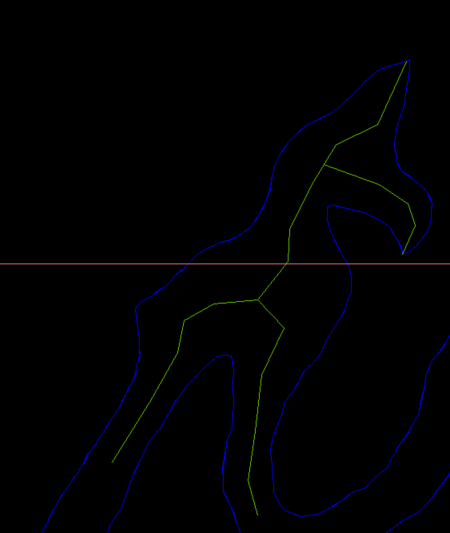
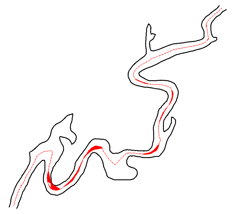
I think with those big side offshoots you need to break the river into multiple plines so you would have two or more centrelines lines in that situation. As suggested by @SLW210 The problem will be how to work out the break offset shape.. Ps image dummied up.

-

Change MText Width (after width has been changed))
Lee Mac replied to ILoveMadoka's topic in AutoLISP, Visual LISP & DCL
This should achieve the desired result without overriding nested width formatting - (defun c:mtw ( / enx idx sel str wid ) (initget 6) (cond ( (not (setq wid (getreal "\nSpecify new width factor: ")))) ( (setq sel (ssget "_:L" '((0 . "MTEXT")))) (repeat (setq idx (sslength sel)) (setq idx (1- idx) enx (entget (ssname sel idx)) str (assoc 1 enx) ) (entmod (subst (cons 1 (addupdatewidth (cdr str) wid)) str enx)) ) ) ) (princ) ) (defun addupdatewidth ( str wid / ps1 ps2 ps3 ) (cond ( (= "" str) str) ( (and (setq ps1 (vl-string-search "{\\W" str)) (setq ps2 (vl-string-search ";" str ps1)) (setq ps3 (vl-string-search "}" str ps2)) ) (strcat (addupdatewidth (substr str 1 ps1) wid) (substr str (1+ ps1) 3) (rtos wid 2) (substr str (1+ ps2) (- ps3 ps2 -1)) (addupdatewidth (substr str (+ ps3 2)) wid) ) ) ( (strcat "{\\W" (rtos wid 2) ";" str "}")) ) ) (princ) -

Can I read and copy Dynamic Block properties to another block reference?
BIGAL replied to p7q's topic in AutoLISP, Visual LISP & DCL
Google "create dynamic block with flip parameter autocad" it was hinted to in the link by Lee. Got some helpful information. Not tested as I use Bricscad which at moment struggles to edit Acad dynamic blocks. To be fixed soon. -
AutoCAD Dimension Settings: Tuesday Tips With Frank
The AutoCAD Blog posted a topic in AutoCAD Blogs
There’s nothing I love more than presenting an exciting topic to our Tuesday Tip readers, so today I’m talking about AutoCAD Dimension Settings. By my count, there are 95 dimension variables. So, sit back and relax, as I work my way through them all. I’m kidding. I’ll be touching on very small percentage of what I consider to be some of most important. Plus, I’ll be using their description from the Modify Dimension Style dialog, instead of the actual dimension variable name. To be honest, most of us never think about the variables that make up your dimension style. And, if set up right, there should be no reason for you to do so. Outside of choosing a different style to use, you may not even be aware of what the Modify Dim Style dialog looks like. If that’s you, you’re in luck. The animation below cycles through the seven tabs at the top of the dialog. You should also note that in each tab, there is a preview box in each, always in the same place, the upper right corner. If you’re of a certain experience level like me, you’ll know what a big deal that is. The Important Stuff About AutoCAD Dimension Settings I’d say at least 90% of the AutoCAD Dimension Settings you’ll find in the Modify dialog control what the dimension object looks like. What terminators are you using? What’s the gap between the object and the dimension line? Where and how is the dimension’s text place? Things like that. Others control how they function, and the settings I’ll be talking about fall into that category. First, in the Text tab, is the text style. The currently active text style may not necessarily match the style that the dim style uses. They are not connected, so it’s important that they match – if that’s what you want. I’ve seen it both ways (usually matching). I’ve been around the CAD block long enough to have worn a path, so in general, I’ve seen it all – or at least a whole lot. Below that, you’ll find Text Height. This setting goes directly to your CAD Standard. It’s the actual height of the dimension text. 3/32” and 1/8” are extremely common when using Imperial units. The next two settings are directly responsible for how your dimensioning method functions. The oldest method (yet still in use today), is to place your dimensions into model space, scaled up to the intended plot scale of the model, where the scale is the inverse value of the drawing’s scale. For instance, if the scale is to be 1/8”=1’-0” when plotted, the inverse scale would be 96. That’s the overall scale setting that we see in the next image. That means all of your dimension features get scaled up 96 times, so that when it gets plotted to scale, everything will be the right size. Like I said, that method is about as old as AutoCAD itself, literally before paper space, so all we had was scaling up the dimensions in model space (which didn’t even have that name until paper space came along). It was either that, or draw the model to scale as you would have done in the days of board drafting. Not really an optimal solution. Now we have more modern methods. If you want to use Annotative dimensions, this is where you’ll set it to do so. Checking the Annotative box will disable the two radio buttons below it. If you want the scale of the paper space viewport to control the feature scaling, choose the top radio button. If you want to go old school, this is where you’ll enter the scale value. The next one is found in the Primary Units tab. This is typically a point of confusion for new users. Quite simply, the units used in your dimension style do not automatically correspond to the overall units defined in your drawing. If you want them to match, which you probably do, you have to set them here as well. At the bottom is Measurement scale. Typically, since you’re drawing at 1:1 scale, you’ll leave this at 1.0. But if your drawing is drawn to scale for some reason, let’s say it’s a tiny part, and you’ve scaled it up 2x, you’d want to set the scale factor to .50 Do you use Alternate Units in your dimensions? If you do, chances are that it’s probably metric. You’ll need to turn the feature on in the Alternate Units tab using the checkbox at the top. Then make sure the multiplier is set correctly. By default it’s already set to 25.4 for metric. If you’re using something else, this is where you’ll set that value. One More Thing About AutoCAD Dimension Settings There’s one other dimension variable that is very important, but it’s not part of your dimension style. It’s a system variable called DIMASSOC. It can be set to either 0, 1, or 2. The default is 2. That means that the definition points of the dimension object are associated to the object’s geometric points. Stretch the object, and the dimension updates. A setting of 1 does not associate the dimension to the geometry, and 0 (zero) creates in essence an exploded dimension. I’m not sure why you’d want to do that, but you do you. This variable is saved in the drawing, so it’s not one of those set it once and it stays that way. Looking Ahead For my next Tuesday Tips, I’ll be looking at editing existing dimensions. In fact, while discussing dimensioning variables here, along with various methods, I’ve got another topic in mind for you. After that, I’ll discuss some of the more important things you should find in your CAD Standards, so stay tuned! More Tuesday Tips Check out our whole Tuesday Tips series for ideas on how to make AutoCAD work for you. The post AutoCAD Dimension Settings: Tuesday Tips With Frank appeared first on AutoCAD Blog. View the full article -
 nada ainiah joined the community
 -

Change MText Width (after width has been changed))
Steven P replied to ILoveMadoka's topic in AutoLISP, Visual LISP & DCL
The code is adding a width string to the text. These characters are hidden but will show up if you click on the text and look at it in the properties menu, or via the LISP line: (assoc 1 (entget(car(entsel)))) In the code it adds {\\W'wf'; to the string where wf is the width factor Something like {\\W0.8;Here is a text string} If you run the code again, it will add another width factor to the text string... but won't remove the first, so you get something like this: {\\W0.5;{\\W0.8;Here is a text string}} - noting that the new text width is applied and then the first one is applied.. result is you only see what was applied first. Need to remove this formatting to the text string before applying a new one. You might also have issues if other text formatting is used, such as underlined, italics, bold... For width you might be able to amend Lee Macs Unformat LISP to just unformat the width portion: https://lee-mac.com/unformatstring.html In these text strings replace with just 'W' ACcFfHLlOopQTW and here ACcFfHLlOoPpQSTW change to SW ... and then apply the new width formatting from your LISP .. though CAD is off so not tested - all part of the fun for you! ...if Lee Mac is passing through, feel free to correct me, though many years later I am just about understanding some of your codes. -
Change MText Width (after width has been changed))
ILoveMadoka posted a topic in AutoLISP, Visual LISP & DCL
I found some code by kent1cooper here (defun C:MTW ; = MText Width (/ ss wf n mt) (if (and (setq ss (ssget "_:L" '((0 . "MTEXT")))) (setq wf (getreal "\nWidth Factor to apply: ")) ); and (repeat (setq n (sslength ss)); then (setq mt (ssname ss (setq n (1- n)))) (setpropertyvalue mt "Contents" (strcat "{\\W" (rtos wf 2) ";" (getpropertyvalue mt "Contents") "}") ); setpropertyvalue ); repeat ); if (princ) ); defun This works great.... BUT once the width has been changed it no longer works. Is it a simple fix to change the width after it has been changed? Ideally select multiple and not have to pick the dropdown to change. If you have a style that has a defined width, the routine works until you change it to something else. If you run STRIPMTEXT on a string, it resets something so the change text code works again.
-
 mistermn joined the community
 -
IIRC, those are tough to manage on GIS programs with Add-ons made with Python, .NET, etc. Remember, real rivers/roads/ROWs have curves and organic shapes, not just straight lines. I did see some information on how to tackle those, hopefully it can be worked out, but don't expect perfection. As I mentioned, from what my daughter said and what I've seen in various related forums, the GIS pros are using whatever program and add-ons they can to get the bulk of it and cleaning up and filling in manually. Most that are doing those shapes want the main channel center, if needed I would ignore the very wide sections and side pieces and get those as center lines running back to the main channel separately. As your example shows, it would take separate polylines, so it will need to account for those sections and then ran again on the offshoots. You still haven't answered all of the questions asked. What type of work are you doing? What you have posted looks to be Civil and/or GIS work. I'll try some more on this when I can, I have also looked at some different shortest path codes, the last example is way over my head in LISP, I'll concentrate on the previous examples then try to run just the main channel on the last example .dwg. I have a full slate at work again today, but I'll try to jump back on this when I get some things out of the way. Home time is limited, but I'll try to get back on this with QGIS solution, I may see if my daughter's coworkers want to take a shot at these.
-
Are you using a LISP? You posted this in the AutoLISP, Visual LISP & DCL Forum. You'll need to post a .dwg and the LISP you use most likely. What are your computer specifications, graphics card, driver, etc.? You might try turning graphics card hardware acceleration on and off.
-
 Sim_Th joined the community
 -

Can I read and copy Dynamic Block properties to another block reference?
p7q replied to p7q's topic in AutoLISP, Visual LISP & DCL
Thanks for the links. @Lee Mac They’re helpful, but my main problem is already-mirrored block references that I receive from others. I’m looking for an AutoLISP routine/approach to fix text inside existing mirrored blocks, not to control how blocks are mirrored in the first place. Do you have any code or examples that could help with this specific case? -
Hi @PGia, wow, you managed to find another example that fails. Good stress testing! The reason mine fails is because it ignores the offset lines that are split in two or more parts. But some of the parts are still be usable and should be used. I looked into fixing this and managed to add those lines, but this resulted in some other problems so I didn't update the code on the earlier post yet. The zigzag problem is coming back on your example. The result below. I really need to find a solution for that, but it looks like I might have to use a path finding algorithm which would slow down the code a lot. Sorting the points by distance on the offset line is not enough anymore.
-
Can I read and copy Dynamic Block properties to another block reference?
Lee Mac replied to p7q's topic in AutoLISP, Visual LISP & DCL
Based on the title of your thread, here's an existing program to match dynamic block properties: https://www.theswamp.org/index.php?topic=44444.msg496892#msg496892 Where mirroring text in blocks is concerned, here's some food for thought: https://www.theswamp.org/index.php?topic=46271.msg513250#msg513250 -
Can I read and copy Dynamic Block properties to another block reference?
p7q replied to p7q's topic in AutoLISP, Visual LISP & DCL
It's so usefull. Thanks @BIGAL for the help on reading/copying dynamic block properties – the approach you suggested for dynamic blocks seems to work quite well in my tests, and it looks like I can keep the dynamic behavior while transferring the values to another block reference. To clarify my actual use-case a bit more (it wasn’t very clear in my original question): What I’m really trying to solve is the situation where a block reference is mirrored, and the text inside that block (TEXT/MTEXT/etc.) becomes mirrored/unreadable. My goal is to “fix” the mirrored text so that it reads normally again, while still keeping the block as a block reference. Right now my algorithm roughly does this: Find mirrored block references (negative X/Y scale). Explode that mirrored block reference. From the resulting entities, create a new block definition. Insert this new block back with adjusted scale/rotation, so that the text appears non-mirrored/readable. This works reasonably well in some limited cases: Non-dynamic blocks Simple blocks without deep nesting But there are some important drawbacks: For dynamic blocks, exploding/rebuilding is not acceptable because I lose all the dynamic behavior (this is why your dynamic-block-based suggestion is very useful there). For blocks with attributes, the whole “explode + rebuild” idea is basically wrong for my use-case: With MIRRTEXT = 0, the attribute text itself is already displayed correctly (not mirrored) in a mirrored block reference, but other TEXT/MTEXT objects inside the same block are still mirrored. If I explode and rebuild that block, I’m just introducing more risk of breaking the attributes, even though they were already visually correct. For nested blocks, doing this recursively at multiple levels becomes very complex and potentially slow. In general, the “explode → rebuild block → insert new block” pattern feels too heavy and fragile if I want to handle all combinations (dynamic, attributes, nesting, etc.). It quickly turns into a very complicated algorithm that I’m not sure is worth the performance and maintenance cost. So my question now is more about design/approach: Is there a better/cleaner way (algorithm or pattern) to fix mirrored TEXT/MTEXT (and similar objects) inside mirrored block references, without relying on a full explode + re-create cycle, and that can coexist more gracefully with dynamic blocks, attributes (which are already correctly oriented with MIRRTEXT=0), and nested blocks? I’m not necessarily asking for full code, more for ideas on how you would approach this problem at a higher level. Any suggestions on a different strategy would be appreciated. -
 wanlongstone changed their profile photo
 -
wanlongstone joined the community
-
 fff joined the community
 -
 richardjunn joined the community
 -
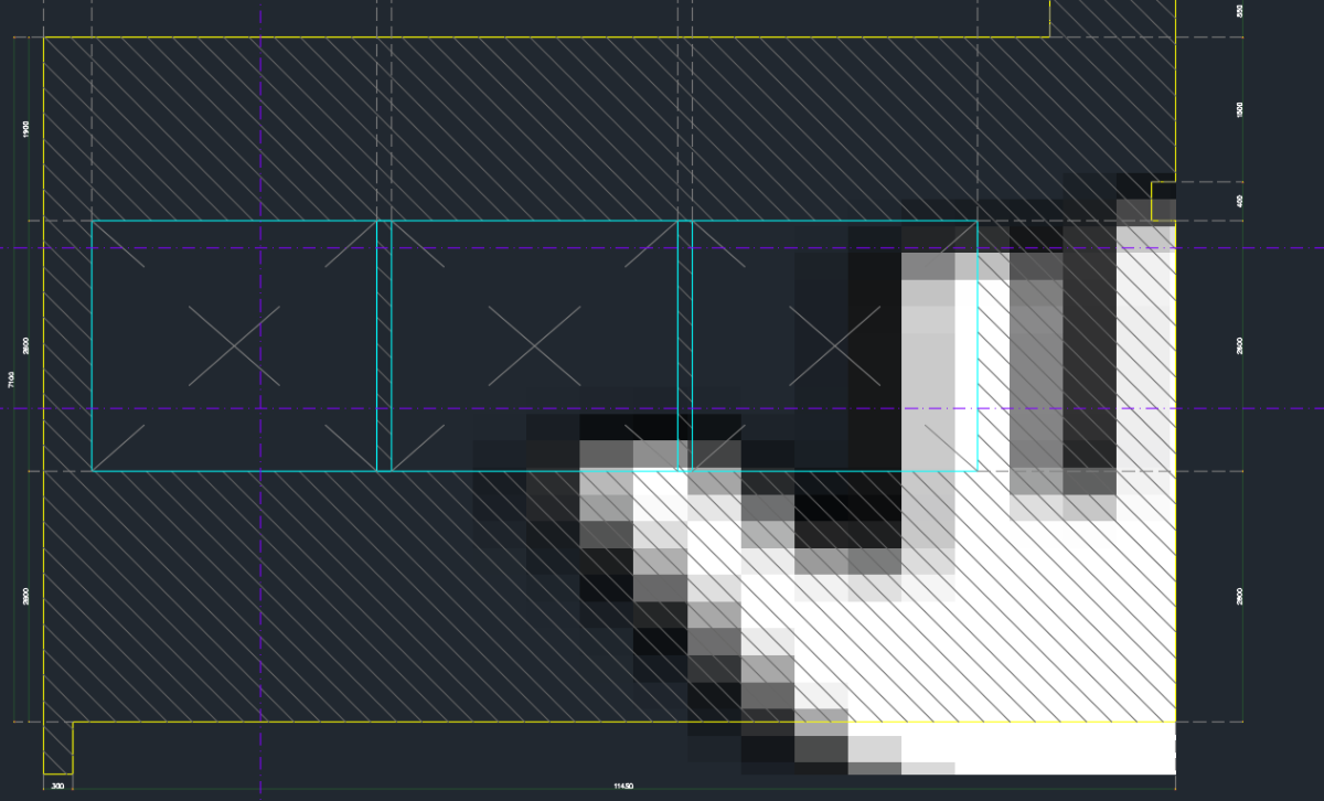
I have been having this issues with the Wipeout command in Autocad 2026 which when you zoomed in, the inside of the wipeout suddenly has random sign or hand sign however it is gone when i zoomed out and it still appears when plotting as well, can anyone help??