All Activity
- Today
-
There is all sorts of problems with 3 arcs/circles touching. I don't think can do a reactor but as you have already drawn something you should be able with a lisp to do a re-calc the tangent points. A reactor would have to some how find all 3 objects I think a lisp would be easier. Can you clarify the 3 objects by posting a sample dwg with some examples.
-
@CivilTechSource I checked it out looks very useful, not sure the surface analysis will do what is required, ie use it to import Surface Styles. May need something similar export out the surface label styles details. Did you try it ?
-
The desire is to find a way to keep a 'live.circle' tangent connected to the three edges made/picked first. If any of the edges are changed, the circle will follow and adjust so it remains tan.connected. I could draw three lines and a circle but to activate a/this desired reactor is not my language (yet). 1. select or draw segments to attach cir.tan to 2. lsp: draw tangent circle using segments of 1. 3. lsp: activate reactor to maintain tangents btw.. here's a similar one which has reactor ability https://www.theswamp.org/index.php?topic=8861.msg113627#msg113627
-

Cross Section area and Its calculation
BIGAL replied to ..very.'s topic in AutoLISP, Visual LISP & DCL
A quick way to get true areas where you have Horizontal and vertical scales is to block all the cross sections and then reset the Hor & ver scale. Did you google this has been asked many times before. Of course the simplest is use a 3rd party Civil software add on they have volumes all built in. Will pay for its self very quickly. -
Nice @alanjt. Have you thought about using a Mline you can set the offsets and layers. If it's wrong flip line. In a lisp can reverse lines, plines and mlines. The other thing of course is offset 3d line work, including +- to rl's.
-
The desire is to find a way to keep a 'live.circle' tangent connected to the three edges made/picked first. If any of the edges are changed, the circle will follow and adjust so it remains tan.connected. I could draw three lines and a circle but to activate a/this desired reactor is not my language (yet). 1. select or draw segments to attach cir.tan to 2. lsp: draw tangent circle using segments of 1. 3. lsp: activate reactor to maintain tangents
-

Pathfinding in AutoCAD with the A-Star Algorithm (A*)
ymg3 replied to heschr's topic in AutoLISP, Visual LISP & DCL
Here I've revised Helmut's code and made it faster. ;; ; ;; Pathfinding with the A* algorithm by ymg 22/07/2024 ; ;; ; ;; Revised a prog by HELMUT SCHRÖDER - heschr@gmx.de - 2014-09-14 ; ;; found at Cadtutor.net ; ;; ; ;; Kept the same format for edges list but added lines as valid choice ; ;; Format: (((x1 y1) (x2 y2)) (((x2 y2) (x3 y3))....(xn yn))) ; ;; ; ;; The user is asked to pick a start and an endpoint. ; ;; The program will find the shortest path in a network of connected ; ;; polylines and/or lines and draw a new polyline representing the result. ; ;; ; ;; Two lists of nodes openlst and closelst are created from the above ; ;; mentionned edges list. The format of a node list is: ; ;; (((Point) (Prev Point) Cumulated_Distance Estimated_Total_Distance)...) ; ;; ; ;; Main change from origina are: ; ;; - cons the list instead of append ; ;; - vl-sort the openlist instead of the quicksort ; ;; - Replaced and renamed some vars and subroutine. ; ;; - Added fuzz 1e-4 to all points comparison ; ;; - Change the get_path function ; ;; - Added line as possible edges ; ;; - Added an error handler ; ;; - Added a timer to the search portion of the program ; ;; ; ;; The above changes amounted to an acceleration of about 4x from the ; ;; original program. ; ;; : ;; If you compile this program to a .fas you'll get more than 10x faster. ; ;; ; (defun c:A* ( / ssl ssp i edges startp endp openlst closelst found acdoc Edgelay Pathlay Pathcol Pathlwt) (vl-load-com) ; Changes values of following 4 global variables to suit your need. ; (setq Edgelay "Edges" Pathlay "Path" Pathcol 1 ; 1=Red 2=Yellow etc. ; Pathlwt 70 ; lineweight for path 0.7mm ; ) (or acdoc (setq acdoc (vla-get-activedocument (vlax-get-acad-object)))) (set_errhandler '("CLAYER" "OSMODE" "CMDECHO")) (setvar 'CMDECHO 0) (setvar 'OSMODE 1) (if (setq ssp (ssget '"X" (list (cons 0 "LWPOLYLINE") (cons 8 Edgelay)))) (foreach en (mapcar (function cadr) (ssnamex ssp)) (setq edges (append edges (mk_edge (listpol2d en)))) ) ) (if (setq ssl (ssget '"X" (list (cons 0 "LINE") (cons 8 Edgelay)))) (foreach en (mapcar (function cadr) (ssnamex ssl)) (setq edges (cons (list (butlast (vlax-curve-getstartpoint en)) (butlast (vlax-curve-getendpoint en))) edges)) ) ) (setq startp (butlast (getpoint "\nPick Start Point: ")) ; Startpoint - reduced to 2D ; endp (butlast (getpoint "\nPick End Point: ")) ; Endpoint - reduced to 2D ; openlst (list (list startp '(0 0) 0.0 (distance startp endp))) ; Add starting node to openlst ; ) (vla-startundomark acdoc) (setq ti (getvar 'MILLISECS)) (while (and openlst (not found)) (setq node (car openlst)) (if (equal (car node) endp 1e-4) (setq found T closelst (cons node closelst)) (setq closelst (cons node closelst) openlst (upd_openlst edges node endp (cdr openlst) closelst) ) ) ) (if found (mk_lwp (get_path closelst)) (alert "No path was found") ) (princ (strcat "\nExecution time:" (itoa (- (getvar 'MILLISECS) ti)) " milliseconds.")) (*error* nil) ) ;; ; ;; upd_openlst ; ;; ; ;; Each node of the openlst is passed to this sub and we scan the edges list ; ;; to find the corresponding edges. Then both points of the edges are tested ; ;; for equality to the nodes. The fixed cost (distance) is updated and so is ; ;; the estimated total distance. Updates are first put in a temporary node. ; ;; ; ;; We then proceed to test if the temp variable is already in the closelst ; ;; and proceed to the next edge. ; ;; ; ;; If temp is true and temp is not in closelst we go to the recursive sub ; ;; in_openlst which adjust the values and return the updated openlst : ;; ; ;; Upon return we sort the openlst on smallest estimated distance ; ;; and return the openlst to the main routine ; ;; ; (defun upd_openlst (edges node endp openlst closelst / pt fcost p1 p2 d temp) (setq pt (car node) fcost (caddr node)) (while edges (setq p1 (caar edges) p2 (cadar edges) edges (cdr edges) d (distance p1 p2) temp nil) ;Testing both points of an edge and building a temporary node ; (cond ((equal pt p1 1e-4) (setq temp (list p2 p1 (+ fcost d) (+ fcost d (distance p2 endp))))) ((equal pt p2 1e-4) (setq temp (list p1 p2 (+ fcost d) (+ fcost d (distance p1 endp))))) ) (if (and temp (not (memberfuzz (car temp) closelst))) (setq openlst (in_openlst temp openlst)) ) ) ; Keep openlist sorted on smallest Estimated Total Cost ; (print (vl-sort openlst (function (lambda(a b)(< (cadddr a) (cadddr b))))) ) ) ;in_lst Replaced by memberfuzz ; ;(defun in_lst (pt lst) ; (cond ; ((not lst) nil) ; ((equal pt (caar lst) 1e-4) lst) ; (T (in_lst pt (cdr lst))) ; ) ;) ; returns a new openlst with a double exchanged if cost is lower ; ;; ; (defun in_openlst (node lst) (cond ((not lst) (list node)) ((equal (car node) (caar lst) 1e-4) (if (< (cadddr node) (cadddr (car lst))) (cons node (cdr lst)) lst ) ) (T (cons (car lst) (in_openlst node (cdr lst)))) ) ) (defun in_openlst2 (node lst / s c) (setq s (splitat (caar node) lst) c (cadddr node)) (cond ((not lst) (list node)) ((not (car s)) (cons node (cadr s))) ((not (cadr s)) (cons node (car s))) (T (if (< (cadddr node) (cadddr (cadr s))) (append (car s) (cons node (cdr s))) lst )) ;(T (c ns node lst)) ) ) ;; ; ;; listpol2D by ymg (Simplified a Routine by Gile Chanteau ; ;; ; ;; Parameter: en, Entity Name or Object Name of Any Type of Polyline ; ;; ; ;; Returns: List of Points in 2D WCS ; ;; ; ;; Notes: Requires butlast function for 2d points. ; ;; ; (defun listpol2d (en / i lst) (repeat (setq i (fix (1+ (vlax-curve-getEndParam en)))) (setq lst (cons (butlast (vlax-curve-getPointAtParam en (setq i (1- i)))) lst)) ) ) ;; ; ;; mk_edge ; ;; ; ;; From a list of consecutives points as supplied by listpol2D, ; ;; Returns a list of edges (((x1 y1)(x2 y2)) ((x2 y2)(x3 y3))...) ; ;; ; (defun mk_edge (lst) (mapcar (function (lambda (a b) (list a b ))) lst (cdr lst)) ) ;; ; ;; butlast ; ;; ; ;; Returns a list without the last item ; ;; Used here mainly to change points to 2D ; ;; ; (defun butlast (lst) (reverse (cdr (reverse lst)))) ;; ; ;; get_path ; ;; ; ;; Returns The list of points of shortest path found from closelst. ; ;; ; (defun get_path (lst / path) (setq path (list (caar lst)) prev (cadar lst) lst (cdr lst)) (while (setq lst (memberfuzz prev lst)) (setq prev (cadar lst) path (cons (caar lst) path) ) ) path ) ;; ; ;; memberfuzz by Gile Chanteau ; ;; ; ;; Modified to work with nodes list ; ;; ; (defun memberfuzz (p lst) (while (and lst (not (equal p (caar lst) 1e-4))) (setq lst (cdr lst)) ) lst ) (defun splitat (p lst / tr) (while (and lst (not (equal p (caar lst) 1e-4))) (setq tr (cons (car lst) tr) lst (cdr lst)) ) (list (reverse tr) lst) ) (defun truncfuzz (p lst) (if (and lst (not (equal p (caar lst) 1e-4))) (cons (car lst) (truncfuzz p (cdr lst))) ) ) (defun posfuzz (p lst) (- (length lst) (length (memberfuzz p lst))) ) (defun rotleft (lst) (append (cdr lst) (list (car lst)))) (defun rotright (lst) (cons (last lst) (butlast lst))) ;; ; ;; mk_lwp ; ;; ; ;; Draw an lwpolyline given a point list ; ;; ; ;; Will be drawn on layer with color and lineweight defined by Variables ; ;; at beginnung of program. ; ;; ; (defun mk_lwp (pl) (entmakex (append (list (cons 0 "LWPOLYLINE") (cons 100 "AcDbEntity") (cons 100 "AcDbPolyline") (cons 8 Pathlay) (cons 62 Pathcol) (cons 90 (length pl)) (cons 70 0) (cons 370 Pathlwt) ) (mapcar (function (lambda (a) (cons 10 a))) pl) ) ) ) ;; Error Handler by Elpanov Evgenyi ; (defun set_errhandler (l) (setq varl (mapcar (function (lambda (a) (list 'setvar a (getvar a)))) l)) ) (defun *error* (msg) (mapcar 'eval varl) (if (and msg (not (wcmatch (strcase msg) "*BREAK*,*CANCEL*,*EXIT*"))) (princ (strcat "\nError: " msg)) ) (vla-endundomark acdoc) (princ) ) (princ "A* to start") Astar rev3.lsp astar test.dwg -

Moving objects within polyline to different layer
mhupp replied to Hsanon's topic in AutoLISP, Visual LISP & DCL
Might want to take those down and only upload a "Sample" drawing that doesn't have a title block with addresses and names or map. -edit Read this about polylines with arc's https://www.cadtutor.net/forum/topic/76326-selection-set-that-selects-objects-inside-a-curved-polyline/#findComment-603264 I think final code is on page 2. -
 proa joined the community
 -
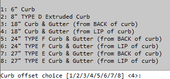
See attached. It does not set layers, but I use this to generate curb offsets, based on multiple selected lines/etc. OffsetMultiple.lsp

-
 caduvil joined the community
 -

Moving objects within polyline to different layer
Hsanon replied to Hsanon's topic in AutoLISP, Visual LISP & DCL
apologies for the delayed response..... Can you try out the program on these files???? It works just fine on a new file made up of simple oblects... but just doesn't work on typical files on which i have to work further. Some times, it works on part of the objects.... (some objects get converted to "exist" layer and some dont) Are there some objects the survey drawing has which are causing the program to mess up ??? Just last try.... otherwise ill get back to my painstaking manual changes. Many many thanks ganges Sugam Survey with Tree details 14.8.25.dwg JC 6 ROYED ST-Basu survey.dwg -
@ScottMC Please upload your SAMPLE.dwg and Sample.lsp as to see what you did and want to do
-
You can install the UKIE package and it has a built-in function to export and import styles. https://www.autodesk.com/sites/default/files/file_downloads/UKIE User Guide and Reference.pdf The Civil3D UKIE package is after 2023 or 2024 can be found in the AutoDesk Product page under Civil3d.
-

Penn Foster Student Suffering with Oleson Village Map!!!
ReMark replied to AutoCad Student's topic in Student Project Questions
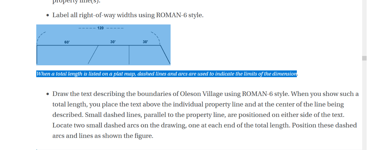
You're right, there is no mention of a layer that makes use of the dashed linetype in this project. I suggest you create a layer called "Arc", layer color "white" and assign it the "Dashed" linetype. There are only four overall (boundary) dimensions that will require manually created arcs. As for the title block and border draw it per the instructions. When completed use the Scale command to scale it up. The scale factor should be 50. -
 SHU joined the community
 -

Cross Section area and Its calculation
SLW210 replied to ..very.'s topic in AutoLISP, Visual LISP & DCL
Your profile does not show what CAD software you are using. Yes, you need to post a drawing, preferably showing a before and after. -

Cross Section area and Its calculation
Steven P replied to ..very.'s topic in AutoLISP, Visual LISP & DCL
Have you got a sample drawing which might show bit more detail? should be possible though - simplest if you have the cross section drawn out is hatch, use properties to get the hatch area. I suspect it will be more complex than that -

Penn Foster Student Suffering with Oleson Village Map!!!
Val replied to AutoCad Student's topic in Student Project Questions
Hello, I'm at the final steps for this project and I'm stuck on 2 parts. First is the dimensioning the total length of the lot sides added together. It says to use a dashed line for the arc and line, but the list of layers never mentions a layer that uses dashed lines. Is this some sort of annotation setup that I'm overlooking? And is there a command for the having the ends of the dimension being arcs, or do I need to make those manually? Second part is the setup for the border. I understand it's a 24 x 36 and that 1 unit equals 1 foot and that I will need to scale it up once created. But then they throw in the line that the actual input is 2 x 3 and I'll have to figure out the math. This is throwing me for a loop, or possibly my brain has just turned to mush from overthinking it. Thanks in Advance for the help.
-
Val joined the community
-
Really enjoy what y'all have done with reactors but have yet to see a live circle using edge tangents. Has this been used in Civil/Mech? Might inspire me to learn a little.. Thanks
- Yesterday
-
 GMboxSMG2 joined the community
 -
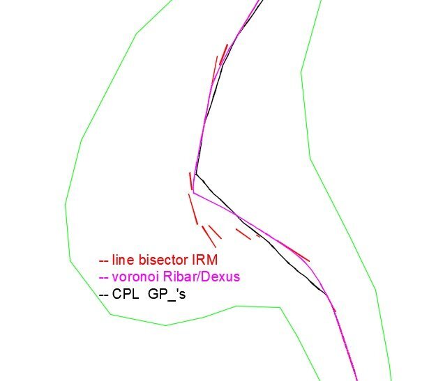
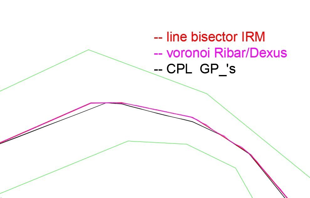
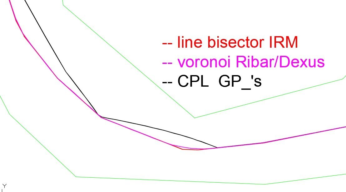
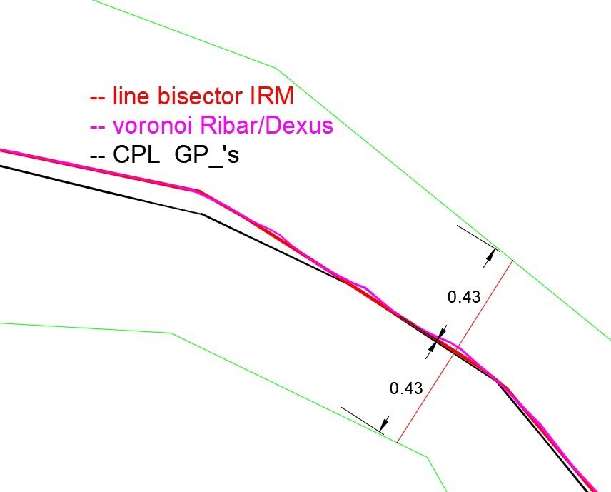
I’ve been experimenting with @lrm's tool to generate segment-by-segment bisectors. In many cases I was able to chain them together without any issues, and the equidistance was achieved. But in the more curved areas, the bisectors produced by each pair of segments lead to results that make it impossible to connect them without losing that equidistance. So I must apologize for my excessive optimism I guess the goal can only be to achieve true equidistance wherever it’s geometrically possible, and where it isn’t, to get the smallest deviation we can. In the attached images you can see in red the result of using Irm’s tool segment by segment and manually joining the endpoints. The result is an equidistant centerline along most of the path. But as you can see in the area where the margins widen significantly, the geometry of the axis becomes very fuzzy. Alongside my manual work with Irm’s tool, you can also see the output from commands "CPL" by @GP_ and "cl" by @dexus/@marko_ribar. In fact, "cl" produces something very close to a true equidistant centerline, although it can be a bit irregular at times. And I suppose the issue with redundant points can be solved easily. So it seems that the solution by Dexus/Ribar is the best one so far.
-
 ..very. joined the community
 -
Hello, I need to find net cross section area of river after proposing design section. Also i need a detailed calculation (like 1/2 x length x width) written below every section. Is it possible using LISP command??
-
 dandeeh joined the community
 -
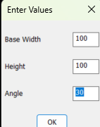
here's the 'BIGAL DCL version.. (defun c:trpz ;; https://www.cadtutor.net/forum/topic/98827-the-coordinates-of-the-trapezoid/ (/ *error* ang radian pt1 pt2 pt3 pt4) (princ "\n Trapezoid from Lower.Left..") (defun *error* ( msg ) (setvar 'cmdecho 0) ;; 5.28.24 (vla-endundomark (vla-get-activedocument (vlax-get-acad-object))) (if msg (prompt (strcat "\n" msg))) (setvar 'cmdecho 1) (princ "\n") (princ) ) (if (not AH:getvalsm) (load "Multi Getvals.lsp") ) ;_ end of if (setvar 'cmdecho 0) (setq ans (AH:getvalsm (list "Enter Values" ;; title "Base Width " 5 4 "10" "Height " 5 4 "10" "Angle" 5 4 "30" ) ;_ end of list ) ;_ end of AH:getvalsm ) ;_ end of setq (setq Wid (atof (nth 0 ans)) ht (atof (nth 1 ans)) ang (atof (nth 2 ans)) ) ;_ end of setq (if (= ang 90)(c:trpz)) ;; restart if ang 90.. etc (setq radian (* pi (/ ang 180.0))) ;; Determining the starting point (setq pt1 (mapcar (function +) (list 0.0 0.0) (getpoint "\r Specify the Lower.Left Basepoint: ") ;; \r overrights values from Multi.. ) ;_ end of mapcar ) ;_ end of setq ;; Calculating the coordinates of the vertices of a trapezoid (setq pt2 (polar pt1 0.0 wid)) (setq pt3 (polar pt2 (- (* 0.5 pi) radian) (/ ht (cos radian)))) (setq pt4 (polar pt1 (+ (* 0.5 pi) radian) (/ ht (cos radian)))) ;; Drawing a trapezoid (command "_.pline" "_non" pt1 "_non" pt2 "_non" pt3 "_non" pt4 "_C") ;_ end of command (setvar 'cmdecho 1) (*error* nil) (princ) ) ;_ end of defun
-
This macro works in Solidworks 2024. Would someone please help me to get it working properly for 2025? See attached file. Thanks. jn_2.txt
-
Or just (/ pi 6)
-
 dnenad joined the community
 -
 kyle zumwalt joined the community
 - Last week
-
 Diego_74 joined the community
 -
Here is another version of the code ;; Draw of a trapezoid based on the lower base, height and angle of the lateral lines ;; insertion beyond the lower left point of the base line (defun c:DrawTrapWHAng (/ baseWidth height ang radian dx pt1 pt2 pt3 pt4) (setq baseWidth (getreal "Enter the size of the bottom base: ")) (setq height (getreal "Enter the height of the trapezoid: ")) ;; The angle between the vertical and the lateral side (in degrees) ; (setq ang 30.0) ; The angle is set to 30 ;; You can set any angle manually (in degrees) (setq ang (getreal "Enter the angle between the vertical and the side (in degrees): ")) ;; Converting the angle to radians ;; If you need a fixed angle of 30 degrees (or other), delete the ";" in front of one of the lines below. ; (setq radian (* ang (/ pi 180.0))) ; (setq radian (* (/ 1.0 6.0) pi)) ; or *advice from BIGAL ; (setq radian (/ pi 6)) ; or *advice from Lee Mac (setq dx (* height (/ (sin radian) (cos radian)))) ;; The starting point of the lower base (bottom left) (setq pt1 (getpoint "Specify the starting point of the lower base: ")) ;; Lower right point (setq pt2 (list (+ (car pt1) baseWidth) (cadr pt1))) ;; Upper right point – move outward to the right (setq pt3 (list (+ (car pt1) baseWidth dx) (+ (cadr pt1) height))) ;; Upper left point – move outward to the left (setq pt4 (list (- (car pt1) dx) (+ (cadr pt1) height))) ;; Drawing a trapezoid (command "_.pline" pt1 pt2 pt3 pt4 "_C") (princ) )
-
I now have tried a few methods, they all miss the center somewhere on the complicated "turns". As I mentioned, even the GIS/Civil programs get similar results at times. I did rabbit hole Bowyer–Watson algorithm and the Delaunay triangulation to obtain a Voronoi diagram of the points. That might be over my head for LISP, I think I have seen references for Python and C# though. I had decent results with my export to CSV and import a center line back, though still has an off center place or two on the OPs example.
-
If you want 30 degree use (* (/ 1.0 6.0) pi) My $0.05 the front end can preset values but change as required. (if (not AH:getvalsm)(load "Multi Getvals.lsp")) (setq ans (AH:getvalsm (list "Enter Values" "Base Width " 5 4 "100" "Height " 5 4 "100" "Angle" 5 4 "30" ))) (setq Wid (atof (nth 0 ans)) ht (atof (nth 1 ans)) ang (atof (nth 2 ans))) (setq ang (* pi (/ ang 180.0))) Multi GETVALS.lsp