All Activity
- Past hour
-

Autolisp for batch freezing & Thaw
Steven P replied to Ikkukp's topic in AutoLISP, Visual LISP & DCL
Can also put these into a routine: (command "-layer" "ON" "ListofLayers, EachLayerSeperated, Withcomma" "") ; Turns layer ON.. try 'OFF' (command "-layer" "FREEZE" "ListofLayers, EachLayerSeperated, Withcomma" "") ; Freezes layer, ty 'Thaw' as well For completion: (command "-layer" "SET" "LayerName" "") ; Sets current layer MHUPPs probably runs faster (like milliseconds) and a nice option to choose the layer, my ideas maybe better if the layer names are set and can be hard coded into the routine... but useless if each drawing / project uses a different name - Today
-

Moving objects within polyline to different layer
mhupp replied to Hsanon's topic in AutoLISP, Visual LISP & DCL
They are either on a locked layer. have an error msg saying # number entitys on locked layer can't move. or inside a block or xref. (setq ss (ssget "WP" Co-ord)) ; Select all entities in window polygon (setq lock (ssget "WP:L" Co-ord)) ; Select entities not on locked layers (setq n (- (sslength ss) (sslength lock))) ; Calculate difference (if (> n 0) ; if n is greater than 0 display msg (prompt (strcat "\n" (itoa n) " entities on a locked layer")) ) -
Depends on what you want to do. this will freeze a layer of the entity you select is on. (defun c:FreezeEntity (/ ent layN layO) (while (setq ent (entsel "\nSelect an entity to freeze layer: ")) (setq layN (cdr (assoc 8 (entget (car ent))))) (setq layO (vla-item (vla-get-Layers (vla-get-ActiveDocument (vlax-get-Acad-Object))) layN)) (vla-put-Freeze layO :vlax-true) (prompt (strcat "\nLayer \"" layN "\" has been frozen.")) ) (princ) ) -Edit Why not just have the calculations on defpoints or some other layer that is set not to print.
-

How to Add Hatch Pattern in AutoCAD: AutoCAD Foundations
The AutoCAD Blog posted a topic in AutoCAD Blogs
A hatch covers a specified area with a pattern, solid color, or gradient fill to identify a material such as concrete, steel, or grass. And it’s a cinch to add a hatch to your drawing. Today’s installment of the AutoCAD Foundation series gives you an easy step-by-step guide on how to add hatch to a closed area. Make a Hatch in AutoCAD When you start the HATCH command, the ribbon temporarily displays the Hatch Creation tab. On this tab, you can choose from more than 70 industry-standard imperial and ISO hatch patterns, along with many specialized options. The simplest procedure is to choose a hatch pattern and scale from the ribbon and click within any area that is completely enclosed by objects. You need to specify the scale factor for the hatch to control the pattern’s size and spacing. How to Use Hatches in AutoCAD Here are some examples of how you can use hatches: For overlapping hatches, fills, wide polylines, and text objects, use the DRAWORDER command to determine which objects are on top or below. For example, you probably want the yellow highway to cross over the blue river rather than the other way around. Keep Going To learn more about hatches, check out the full Place Annotation and Hatch Closed Areas AutoCAD Foundations article that also includes how to add text annotations. The post How to Add Hatch Pattern in AutoCAD: AutoCAD Foundations appeared first on AutoCAD Blog. View the full article -
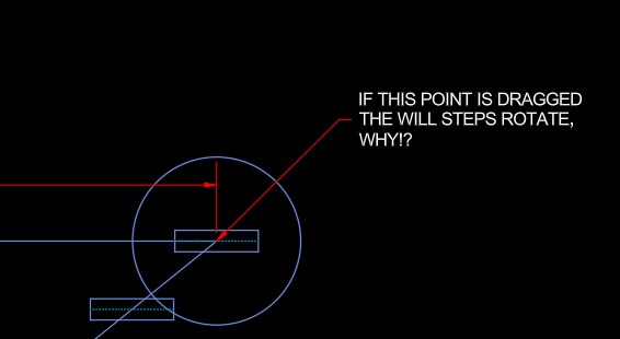
Hello, I seem to have come across an issue with array path, I am using a straight line as my path and when I stretch it in any direction the objects rotate. I intend to include this in a dynamic block, but I have to prove the concept first. This is for a spiral stairway; I have found a way to make AutoCAD do the required calculations but cannot find a way for the path array to be altered without having an issue. I have done this in Autodesk inventor, however we have very few licenses for it, most of which are being used by engineers. Attached is a "Basic" example of the path array. Path Array Sample.dwg

-
I'll try to see how QGIS works if I get any CAD time at home, I started yesterday on it, but I had the latest with QT6 experimental downloaded and the plug-in for centerlines need the non-QT6 version, so spent the time removing and installing the correct version. So, if anybody was interested, be sure to download a version that the plug-in will work with. I also found more information on how the GIS folk tackle this issue and some new Plug-Ins to try for QGIS. Finding centrelines from polygons in QGIS - Geographic Information Systems Stack Exchange line - Creating centerline of river in QGIS? - Geographic Information Systems Stack Exchange HCMGIS — QGIS Python Plugins Repository Geo Simplification (processing) — QGIS Python Plugins Repository Voronoi diagram - Wikipedia Even better, just get the proper tool for the job. Probably less hoops to jump through for ArcGIS Pro, you can utilize the Polygon To Centerline tool. I'll try to remember to check with my daughter what she uses at work.
-
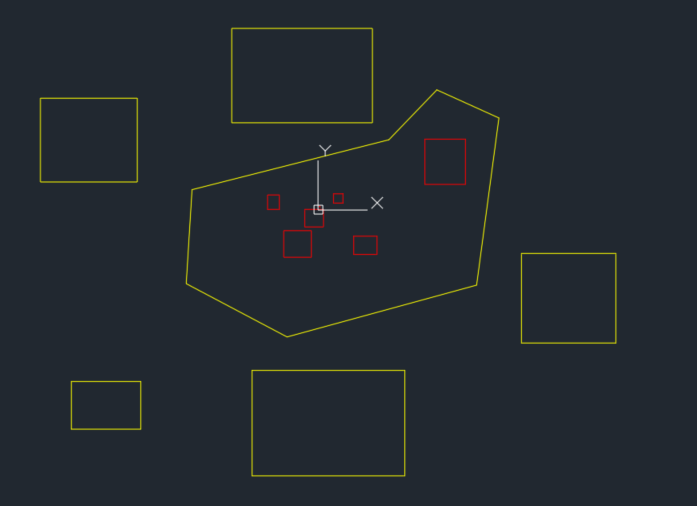
Hi, can anyone help with this? I need a polyline to be created automatically. I draw a line, then I select an existing polyline, and wherever I drop the point, a new polyline should be created. Sample CAD file is attached. Each line distance should be 0.1 ft. Please help with this. Routes.dwg
-

Moving objects within polyline to different layer
nod684 replied to Hsanon's topic in AutoLISP, Visual LISP & DCL
I tried @aridzv first lisp and it's working fine on my end. Yellow ones are moved to layer "Site", the Red ones are moved to "exist" layer as what he mentioned. Though these are all just rectang and PL. haven't tried it with blocks.
-

Moving objects within polyline to different layer
aridzv replied to Hsanon's topic in AutoLISP, Visual LISP & DCL
@Hsanon last try... I used @BIGAL approch for layer criation code to force "exist" layer creation. Beyond that, there's nothing I can think of... see attached code: (defun c:chglyobjpl (/ acdoc p_list p_coord sset ent obj newLayerName newLayerName1 i) (vl-load-com) (setq acdoc (vla-get-ActiveDocument (vlax-get-acad-object))) (if (not (tblsearch "layer" "site")) (command "-layer" "Make" "site" "c" 3 "" "") ) (if (not (tblsearch "layer" "exist")) (command "-layer" "Make" "exist" "c" 50 "" "") ) (princ "\nSelect All Objects To Proccess") (setq ssall (ssget)) (setq p_list (entget (car (entsel "\nSelect the Polyline Boundery For ''exist'' Layer: ")))) (setq i 0) ;;;;;;;;;;;;;;;;;;;;;;;;;;;Change Objects To site Layer;;;;;;;;;;;;;;;;;;;;;;;;;;;;;;;;;;;;;;;;;;;;;;;;;;;;;;;;;;;;;;;;;;;;;;;;;;;;;;;;;; (if ssall (progn (sssetfirst nil nil) (setq newLayerName1 "site");;(getstring T "\nEnter new layer name: ")) (repeat (setq i (sslength ssall)) (setq i (1- i)) (setq ent (ssname ssall i)) (setq obj (vlax-ename->vla-object ent)) (vla-put-Layer obj newLayerName1) );;repeat (vla-Regen acdoc acAllViewports) (sssetfirst nil nil) );;progn (princ "\nNo objects found in the drawing.") );;if ;;;;;;;;;;;;;;;;;;;;;;;;;;;Change Objects To site Layer;;;;;;;;;;;;;;;;;;;;;;;;;;;;;;;;;;;;;;;;;;;;;;;;;;;;;;;;;;;;;;;;;;;;;;;;;;;;;;;;;; (setq ent nil) (setq obj nil) (setq i 0) ;;;;;;;;;;;https://forums.autodesk.com/t5/visual-lisp-autolisp-and-general/selection-set-using-existing-polygon/td-p/11307274 ;;;;;;;;;;;calderg1000 msg-7 (if (setq p_coord (mapcar 'cdr (vl-remove-if-not '(lambda (x) (= (car x) 10)) p_list) );;end setq p_coord );;end if condition (sssetfirst nil (setq sset (ssget "_wp" p_coord))) ) ;;;;;;;;;;;;;;;;;;;;;;;;;;;;Select Objects In polygon;;;;;;;;;;;;;;;;;;;;;;;;;;;;;;;;;;;;;;;;;;;;;;;;;;;;;;;;;;;;;;;;;;;;;;;;;;; ;;;;;;;;;;;;;;;;;;;;;;;;;;;;Change Objects Layer;;;;;;;;;;;;;;;;;;;;;;;;;;;;;;;;;;;;;;;;;;;;;;;;;;;;;;;;;;;;;;;;;;;;;;;;;;;;;;;; (if sset (progn (sssetfirst nil nil) (setq newLayerName "exist");;(getstring T "\nEnter new layer name: ")) (repeat (setq i (sslength sset)) (setq i (1- i)) (setq ent (ssname sset i)) (setq obj (vlax-ename->vla-object ent)) (vla-put-Layer obj newLayerName) );;repeat (vla-Regen acdoc acAllViewports) (sssetfirst nil nil) );;progn (princ "\nNo objects found in the drawing.") );;if ;;;;;;;;;;;;;;;;;;;;;;;;;;;;Change Objects To exist Layer;;;;;;;;;;;;;;;;;;;;;;;;;;;;;;;;;;;;;;;;;;;;;;;;;;;;;;;;;;;;;;;;;;;;;;;;;;;;;;;; (sssetfirst nil nil) (princ) );;end defun -

Moving objects within polyline to different layer
Hsanon replied to Hsanon's topic in AutoLISP, Visual LISP & DCL
Dear Aridzv, The layer was made..... the initial program was working fine, all objects were being moved to layer "site" The second part was having an issue .... I feel it was not selecting the objects within the window / crossing polygon to convert the layer. I did put a video (as an attachment ) ..... Shall do so again.... hope you can view it. changing layers.mp4 -
 Ikkukp joined the community
 -
Hi all, I’m looking for a custom AutoLISP script (for batch freezing/thawing layers before printing). some particular layer i need for drawing internal circulation. bet they are not required during submission. is there any other method ther?
-
 ervanthee joined the community
 - Yesterday
-

Multiple polyline viewport from model to layout
BIGAL replied to iztok14's topic in AutoLISP, Visual LISP & DCL
Thanks Steven added the C :, I normally load lisps like this so last line could be (C:rec2lays) so it runs on load. I don't understand @iztok14 why your bothering making a layout that reflects the rectangs in "Model", you can say plot all rectangs in Model without having to select. Plenty of sample plot lisps out there. -

Anatomy of an AcDbObject in Python.
Danielm103 replied to Danielm103's topic in .NET, ObjectARX & VBA
More in AcDbObject open state AcDbObjects baslically live in three different states, Closed, ForRead, ForWrite In Python (most) every DBObject has a minimum of four constructor overloads # is a new line that does not belong to the database yet dbo = Db.Line() # or dbo = Db.Line(Ge.Point3d(0,0,0),Ge.Point3d(100,0,0)) # is an existing line opened for read dbo = Db.Line(id) # or explicit dbo = Db.Line(id, Db.OpenMode.kForRead) # is an existing line opened for write dbo = Db.Line(id, Db.OpenMode.kForWrite) You can also change the state of the object # upgradeOpen dbo to write dbo = Db.Line(id, Db.OpenMode.kForRead) dbo.upgradeOpen() # upgradeOpen dbo to write dbo = Db.Line(id, Db.OpenMode.kForWrite) dbo.downgradeOpen() -
Select objects inside a boundary, where the boundary can be any curve. In this example, I use AcGeCurve3d::getSamplePoints to build a window, the points are equally spaced by parameter value. You can also use the same technique to build a custom selection fence # see https://github.com/CEXT-Dan/PyRx import traceback from pyrx import Db, Ap, Ed @Ap.Command() def doit(): try: ps, id, _ = Ed.Editor.entSel("\nSelect boundary: ") if ps != Ed.PromptStatus.eOk: raise RuntimeError("Selection Error! {}: ".format(ps)) dbcrv = Db.Curve(id) gecrv = dbcrv.getAcGeCurve() smpls = gecrv.getSamplePoints(100) ps , ss = Ed.Editor.selectWindowPolygon(smpls[0]) if ps != Ed.PromptStatus.eOk: raise RuntimeError("Selection Error! {}: ".format(ps)) for _id in ss.objectIds(): ent = Db.Entity(_id,Db.OpenMode.kForWrite) ent.highlight() except Exception as err: traceback.print_exception(err)
-

i need help in this piece, i need to Create the necessary views. Dimension the part and distribute the dimensions across the drawn views, Create a section cut in the indicated area so you don't have to dimension this radius as a hidden line (use whiche
ReMark replied to Manuel Marroquín's topic in Student Project Questions
Well, it's been five days since you asked for assistance. Have you made any progress at all? I would be willing to show you what I have accomplished but not before I see what you have done. -
There lies the main issue with this, the last sentence is actually incorrect. Unless you have 2 exactly parallel lines/polylines the result is always going to be an approximation, the less different the better, but still just an approximation, even if you compare every conceivable point, if they are different lengths it's odd man out. If it's a very complicated pair of lines, you would need a lot of points to calculate, hence very slow. Jeffery P Sanders Rolling_Ball.lsp appears to get pretty close. This issue comes up all the time, just go to anything related to Civil 3D, GIS, etc. Example https://discourse.mcneel.com/t/finding-the-average-curve-between-two-curves/149668 If you want some unattainable perfection, I suggest you invest in modern software.
-
Multiple polyline viewport from model to layout
Steven P replied to iztok14's topic in AutoLISP, Visual LISP & DCL
try: (rec2lays) Include the ( ) - looks like BigAl has done it all 'wrong' - or it is a part of a more complex thing (a lot more likely) and has forgotten to add the c in the function name, Could also alter first line to be: (defun c:rec2lays ( / ss en..... -
Moving objects within polyline to different layer
aridzv replied to Hsanon's topic in AutoLISP, Visual LISP & DCL
@Hsanon the only way I can reproduse what you show is if "exist" layer dosen't exist. I don't see that layer in the video you shared. MAKE THIS LAYER BEFORE RUNNING THE LISP AS SHOWN IN MY VIDEO. -
Moving objects within polyline to different layer
Hsanon replied to Hsanon's topic in AutoLISP, Visual LISP & DCL
And its not happening on my machine......am i doing anything wrong ???? is it an autocad issue ??? attaching a screen recording... sorry to be such a bother !!!!! changing layers.mp4 -
 hitechcreator joined the community
 -

Multiple polyline viewport from model to layout
iztok14 replied to iztok14's topic in AutoLISP, Visual LISP & DCL
Sorry fot late answer, i was away for weekend. I tried "rec2lays" lisp but doesnt work for me ? noting hapend when i type command "rec2lays". Yes i d like to have vieports in only one layout side by side ? The scale is 1:1 model layout. thy, Iztok -
Moving objects within polyline to different layer
aridzv replied to Hsanon's topic in AutoLISP, Visual LISP & DCL
@Hsanon I tried both lisps and they work. @BIGAL lisp works - after you run the command you need to select the boundery polygon. with my lisp - before runnig it you need to make sure both "exist" and "site" layers exist. in your case you need to create "exist" layer. See attached Video using my lisp. Recording 2025-11-10 110909.mp4 -
Moving objects within polyline to different layer
Hsanon replied to Hsanon's topic in AutoLISP, Visual LISP & DCL
Hi, many thanks for your help Aridzv and BigAl, But, all entities are being converted to layer "site". The ones inside the pline are not being moved to layer "exist" I'm attaching the drawing on which I am testing. surveytest.dwg -
 Bahour joined the community
 -
"Plines in same direction", Yes Lee-Mac has a method also. Note the use of Pedit as Bricscad does not have a "Reverse" command, as at V25. ; Checking if pline is CW or CCW and set to CCW ; Orignal idea by Kent Cooper, 1 August 2018 Offsetinorout.lsp ; By Alan H July 2020 (defun AH:chkcwccw (ent / objnew area1 area2 obj minpoint maxpoint) (setq obj (vlax-ename->vla-object ent)) (vla-GetBoundingBox obj 'minpoint 'maxpoint) (setq pointmin (vlax-safearray->list minpoint)) (setq pointmax (vlax-safearray->list maxpoint)) (setq dist (/ (distance pointmin pointmax) 20.0)) (vla-offset obj dist) (setq objnew (vlax-ename->vla-object (entlast))) (setq area1 (vlax-get objnew 'Area)) (vla-delete objnew) (vla-offset obj (- dist)) (setq objnew (vlax-ename->vla-object (entlast))) (setq area2 (vlax-get objnew 'Area)) (vla-delete objnew) (if (> area1 area2) (command "Pedit" ent "R" "") ) (princ) ) (defun c:CWCCW ( / *error* x ent oldsnap doc ss) (setq doc (vla-get-activedocument (vlax-get-acad-object))) (vla-startundomark doc) (setq oldsnap (getvar 'osmode)) (setvar 'osmode 0) (prompt (strcat "\nSelect Plines to check")) (if (setq ss (ssget '((0 . "*POLYLINE")))) (progn (repeat (setq x (sslength ss)) (setq ent (ssname ss (setq x (- x 1)))) (AH:chkcwccw ent) ) ) ) (vla-endundomark doc) (alert (strcat (rtos y 2 0) " Plines reversed")) (setvar 'osmode oldsnap) (princ) ) (vl-load-com) (prompt "\nType CWCCW to set plines to CCW") (c:CWCCW)
-
 tranbao17 joined the community
 - Last week
-
 Craig Rathke joined the community
 -
@BIGAL You lisp works very well, but I spend alot of time having to delete offsets if I'm not sure where the true start of line is....especially with close polylines. It will always seems to offset the wrong direction and I end up having to reverse the original closed polyline. (FYI I am trying to use a slightly altered version of your code, using a -0.5' offset for the back of curb since I want to offset to both sides based on the initially drawn face of curb for parking lots.) Is there any way the code can be altered in this way: Instead of selecting the beginning point of the object, you just select the object normally, then it prompts you to select the side of the back of curb (in your code, that would be the off1) and then I get an offset to both sides of the selected line..a BOC (off1) and an EOP (off2). This adds an extra click but makes sure I offset the correct direction. I'm not sure how to begin to do this. Any help would be appreciated. Thanks!!! -Craig