All Activity
- Past hour
-
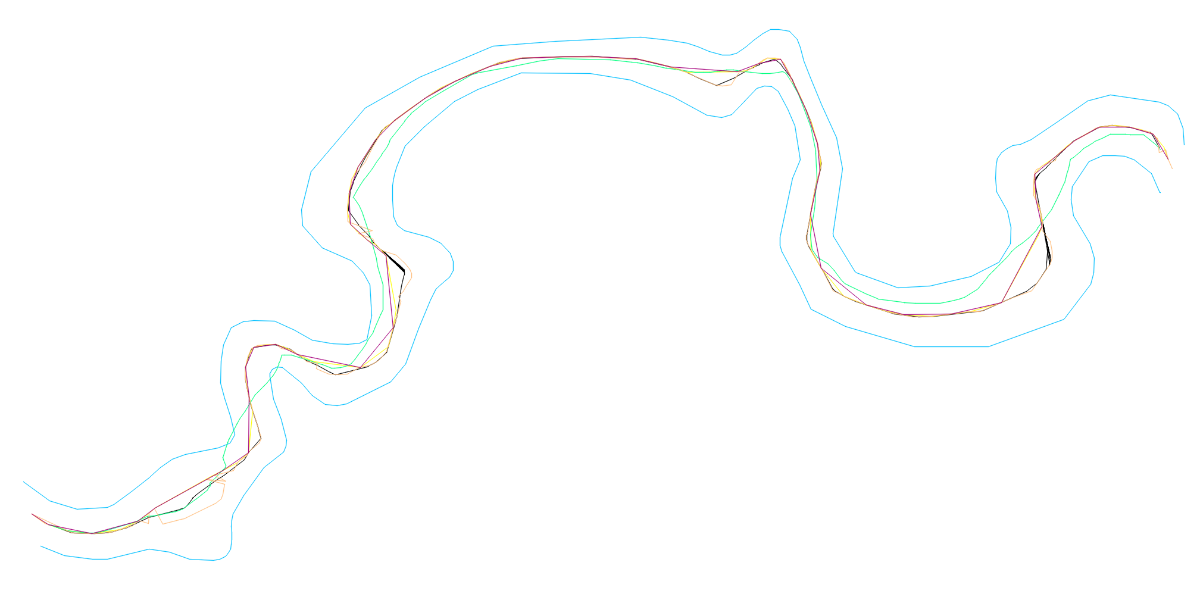
I’ve always thought that a centerline should keep the same distance to the left and right, in the direction of travel. But from a geometric standpoint, maybe it should be as you say.I won’t get into that controversy. Perhaps that approach does make it possible to obtain the centerline in more situations. Regarding @SLW210’s suggestion that I upload a drawing to put the proposed Lisp codes to the test, I think the most appropriate example is the bank of a small river. I trimmed a section and ran the codes by @dexus, @Lee Mac, @SLW210, @mhupp, and @GP_ on it. The geometry of the riverbanks seems to be quite stressful for all the codes, although Dexus’s code only loses control in a couple of areas. I’m attaching the file with all of this for anyone who wants to take a look. AxisExple2.dwg

- Today
-

I can no longer put the autocad bar back like the one in the image, how can I go? Thank you
oddssatisfy replied to Giovannino60's topic in Hardware & Operating Systems
Type RIBBON in the command line and press Enter to restore the toolbar. If that doesn’t work, type WORKSPACE and select “Drafting & Annotation.” If it’s still missing, close AutoCAD and use “Reset Settings to Default – AutoCAD 2021” from the Windows Start menu to fully restore all toolbars. -
@PGia Thanks for the encouragement and checking the results. I measure from the vertices instead of the lines. Those are calculated and the lines are just to connect the points. So perpendicular to the middle of segments of the centerline will always be a bit off, but if you measure from the vertices it should be centered correctly. Just like @GP_ said. I kept going in the same direction and I have made some improvements and got rid of some bugginess: The centerline should be a little more accurate now because of extra measurements (blue line) Crossing polylines get sharp corners on negative side Corner checks are done on all intersections of temporary line now (red line) More error checking so it doesn't crash on some of the example lines I left all of the 'animation' code commented out so you can give it a try ;| ; Calculate centerline between two polylines - dexus ; Function checks intersections of the offsets of two lines to create a middle/avarage line. ; https://www.cadtutor.net/forum/topic/98778-hybrid-parallel/page/6/#findComment-677246 ; Version 0.1 - Initial release 19-11-2025 ; Version 0.2 - Added corner support on negative side of crossing polylines 27-11-2025 ; Version 0.3 - Extra check using distance between vertex and closest point 28-11-2025 ; Version 0.4 - Added error handler 28-11-2025 |; (defun c:cl (/ corners ent1 ent2 loop maxlen offset offsetdistance pts s1 s2 ss start te0 te1 te2 LM:ProjectPointToLine LM:intersections _addPoints _avarageAngle _cornerOffset _doOffset _getAnglesAtParam _getLength _polyline _side _wait *error*) (defun *error* (st) (if (wcmatch (strcase st t) "*break,*cancel*,*exit*") (redraw) (progn (vl-bt) (princ (strcat "\nOops! Something went wrong: ") st) ) ) (if (not (vlax-erased-p te0)) (entdel te0)) (if (and te1 (not (vl-catch-all-error-p te1))) (mapcar 'vla-delete te1)) (if (and te2 (not (vl-catch-all-error-p te2))) (mapcar 'vla-delete te2)) (princ) ) ;| ; Draw Polyline - dexus ; Draw a polyline from a list of points, but filter out colinear points ; @Param lst list of points ; @Returns ename of polyline |; (defun _polyline (lst closed / prev pts) (while lst (cond ( (and (cdr lst) prev (or (equal (cdr lst) prev 1e-8) ; Remove duplicate points (null (inters prev (car lst) prev (cadr lst))) ; Remove collineair points ) ) ) ((setq pts (cons (cons 10 (setq prev (car lst))) pts))) ) (setq lst (cdr lst)) ) (entmakex (append (list (cons 0 "LWPOLYLINE") (cons 100 "AcDbEntity") (cons 100 "AcDbPolyline") (cons 90 (length pts)) (cons 8 (getvar 'clayer)) (cons 70 (if closed 1 0)) ) (reverse pts) ) ) ) (defun _side (pline pnt / cpt end target der) ; https://www.theswamp.org/index.php?topic=55685.msg610429#msg610429 (setq cpt (vlax-curve-getClosestPointTo pline pnt) end (vlax-curve-getEndParam pline) target (vlax-curve-getParamAtPoint pline cpt) der (if (and (equal target (fix target) 1e-8) (or (vlax-curve-isClosed pline) (and (not (equal (vlax-curve-getStartParam pline) target 1e-8)) (not (equal end target 1e-8))) ) ) (mapcar '- (polar cpt (angle '(0 0) (vlax-curve-getFirstDeriv pline (rem (+ target 1e-3) end))) 1.0) (polar cpt (angle (vlax-curve-getFirstDeriv pline (rem (+ (- target 1e-3) end) end)) '(0 0)) 1.0) ) (vlax-curve-getFirstDeriv pline target) ) ) (minusp (sin (- (angle cpt pnt) (angle '(0.0 0.0) der)))) ) ;; Intersections - Lee Mac ;; mod - [int] acextendoption enum of intersectwith method (defun LM:intersections ( ob1 ob2 mod / lst rtn ) (if (and (vlax-method-applicable-p ob1 'intersectwith) (vlax-method-applicable-p ob2 'intersectwith) (setq lst (vlax-invoke ob1 'intersectwith ob2 mod)) ) (repeat (/ (length lst) 3) (setq rtn (cons (list (car lst) (cadr lst) (caddr lst)) rtn) lst (cdddr lst)) ) ) (reverse rtn) ) (defun _getLength (ent) (- (vlax-curve-getDistAtParam ent (vlax-curve-getEndParam ent)) (vlax-curve-getDistAtParam ent (vlax-curve-getStartParam ent)) ) ) (defun _wait (msec) (not ( (lambda (start) (while (< (- (getvar 'millisecs) start) msec)) ) (getvar 'millisecs) ) ) ) (defun _addPoints (lst ent pts / len) (setq len (_getLength ent)) (setq lst (mapcar (function (lambda (pt) (list (/ (vlax-curve-getDistAtPoint ent pt) len) pt))) lst)) (setq pts (append lst pts)) ; Animation ; (setq pts (vl-sort pts (function (lambda (a b) (< (car a) (car b)))))) ; (redraw) ; ( ; (lambda (lst) ; (while (cadr lst) ; (grdraw (cadar lst) (cadadr lst) 3) ; (setq lst (cdr lst)) ; ) ; ) ; pts ; ) ; (vla-update ent) ; (_wait 40) ; End animation pts ) (defun _doOffset (offset / lst rtn) ; Global vars: pts ent1 ent2 s1 s2 te1 te2 (setq te1 nil) (setq te2 nil) (setq rtn (cond ((equal offset 0.0 1e-8) (if (setq lst (LM:intersections ent1 ent2 acExtendNone)) (setq pts (_addPoints lst ent1 pts)) ) lst ) ( (or ; Make offset (vl-catch-all-error-p (setq te1 (vl-catch-all-apply 'vlax-invoke (list ent1 'Offset (if s1 offset (- offset)))))) (vl-catch-all-error-p (setq te2 (vl-catch-all-apply 'vlax-invoke (list ent2 'Offset (if s2 offset (- offset)))))) ) (princ "\nOffset failed. ") nil ) ((setq lst (LM:intersections (car te1) (car te2) acExtendNone)) (setq pts (_addPoints lst (car te1) pts)) lst ) ) ) (if (and te1 (not (vl-catch-all-error-p te1))) (mapcar 'vla-delete te1)) (if (and te2 (not (vl-catch-all-error-p te2))) (mapcar 'vla-delete te2)) rtn ) ;| ; Project Point onto Line - Lee Mac ; @Param pt point to project ; @Param p1 first point of line ; @Param p2 second point of line ; @Returns projected point |; (defun LM:ProjectPointToLine ( pt p1 p2 / nm ) (setq nm (mapcar '- p2 p1) p1 (trans p1 0 nm) pt (trans pt 0 nm)) (trans (list (car p1) (cadr p1) (caddr pt)) nm 0) ) (defun _getAnglesAtParam (ent pa / ang1 ang2) (if (and (vlax-curve-isClosed ent) (= pa 0)) ; Special case for closed Polyline (setq ang1 (vlax-curve-getFirstDeriv ent 1e-14) ang2 (vlax-curve-getFirstDeriv ent (- (fix (vlax-curve-getEndParam ent)) 1e-14))) (setq ang1 (vlax-curve-getFirstDeriv ent (+ pa 1e-14)) ang2 (vlax-curve-getFirstDeriv ent (- pa 1e-14))) ) (if (and ang1 ang2) (list (angle '(0 0 0) ang1) (angle '(0 0 0) ang2) ) ) ) ;| ; Avarage Angle - dexus ; Get angle of a line between two angles ; @Param ang1 real - Angle in radians ; @Param ang2 real - Angle in radians ; @Returns real - Angle in radians |; (defun _avarageAngle (ang1 ang2) (if (< (rem (+ ang1 pi) (+ pi pi)) (rem (+ ang2 pi) (+ pi pi)) ) (+ (* (- ang2 ang1) 0.5) ang1) (+ (* (- ang1 ang2) 0.5) ang2) ) ) ;| ; Calculate exact offset distance on a corner - dexus ; pt1 - Point on corner ; pt2 - Point on other side ; pt3 - Center for bisector ; pt4 - Target for corner of the offset ; pt5 - Find perpendicular point for offset distance ; / ; / ; -------- pt1 pt5 ; \ / ; pt4 ; \ ; ---- pt3 ----- pt2 ----- ; ; @Param ent1 Line to check corners ; @Param ent2 Opposing line ; @Returns List of offset distances (pt1 -> pt5) to calculate |; (defun _cornerOffset (ent1 ent2 / ang1 ang2 ang3 index pt1 pt2 pt3 pt4 pt5 rtn) (setq index 0) (repeat (fix (vlax-curve-getEndParam ent1)) (and (setq pt1 (vlax-curve-getPointAtParam ent1 index)) ; Point on corner (setq ang1 (_getAnglesAtParam ent1 index)) ; Angles of pt1 (setq ang1a (_avarageAngle (car ang1) (cadr ang1))) (setq te0 (entmakex (list (cons 0 "line") (cons 10 pt1) (cons 11 (polar pt1 (- ang1a halfPi) 1))))) ; Temp line for finding the angle on the other side (foreach pt2 (LM:intersections (vlax-ename->vla-object te0) ent2 acExtendThisEntity) ; Point on other side (and (setq ang2 (_getAnglesAtParam ent2 (vlax-curve-getParamAtPoint ent2 pt2))) ; Angle of pt2 (if (equal (rem (car ang1) pi) (rem (car ang2) pi) 1e-8) ; Is parallel? (and (setq pt3 (mapcar (function (lambda (a b) (* (+ a b) 0.5))) pt1 pt2)) ; Midpoint (setq ang3 (car ang1)) ; Same angle als ang1 ) (and (setq pt3 (inters pt1 (polar pt1 (car ang1) 1) pt2 (polar pt2 (car ang2) 1) nil)) ; Find center for bisector (setq ang3 (_avarageAngle (angle pt1 pt3) (angle pt2 pt3))) ; Angle of bisector ) ) (setq pt4 (inters pt3 (polar pt3 ang3 1) pt1 (polar pt1 (+ ang1a halfPi) 1) nil)) ; Find target for corner of the offset (setq pt5 (LM:ProjectPointToLine pt4 pt1 (polar pt1 (+ (car ang1) halfPi) maxlen))) ; Find perpendicular point for offset distance (setq rtn (cons (distance pt1 pt5) rtn)) ; Return offset distance ; Animation ; (progn ; (redraw) ; (grdraw pt1 pt2 1) ; (grdraw pt4 pt5 2) ; (grdraw pt1 pt5 2) ; (vla-update ent1) ; (_wait 120) ; ) ; End Animation ) ) ) (if (not (vlax-erased-p te0)) (entdel te0)) (setq index (1+ index)) ) rtn ) (if (and (not (while (cond ((not (setq ss (ssget '((0 . "LWPOLYLINE"))))) (princ "\nNothing selected. Try again...\n") ) ((/= (sslength ss) 2) (princ "\nSelect 2 polylines! Try again...\n") ) ((and (setq ent1 (ssname ss 0)) (setq ent2 (ssname ss 1)) (setq ent1 (vlax-ename->vla-object ent1)) (setq ent2 (vlax-ename->vla-object ent2)) ) nil ; Stop loop ) ) ) ) ent1 ent2 ) (progn (setq s1 (_side ent1 (if (< ; Check closest point for edgecase with crossing lines in oposite directions (distance (vlax-curve-getStartPoint ent1) (vlax-curve-getEndPoint ent2)) (distance (vlax-curve-getEndPoint ent1) (vlax-curve-getEndPoint ent2)) ) (vlax-curve-getEndPoint ent2) (vlax-curve-getStartPoint ent2) ) ) ) (setq s2 (_side ent2 (vlax-curve-getStartPoint ent1) ) ) (if (not (numberp halfPi)) (setq halfPi (* pi 0.5))) (setq maxlen (* 1.1 (max (_getLength ent1) (_getLength ent2) ( (lambda (ent1 ent2 / step de1 div p_step dis dmax) (setq step (/ (setq de1 (vlax-curve-getDistAtParam ent1 (vlax-curve-getEndParam ent1))) 500) div step dmax 0.00) (while (< div de1) (setq p_step (vlax-curve-getPointAtDist ent1 div) dis (distance p_step (vlax-curve-getClosestPointTo ent2 p_step))) (if (> dis dmax) (setq dmax dis)) (setq div (+ div step)) ) dmax ) ent1 ent2 ) ) ) ) (mapcar ; Add half distances from closest point to every vertex (function (lambda (ent1 ent2 / index pt) (setq index 0) (repeat (fix (vlax-curve-getEndParam ent1)) (setq pt (vlax-curve-getPointAtParam ent1 index) corners (cons (* (distance pt (vlax-curve-getClosestPointTo ent2 pt)) 0.5) corners) index (1+ index)) ; Animation ; (redraw) ; (grdraw pt (vlax-curve-getClosestPointTo ent2 pt) 4) ; ( ; (lambda (mid) (grdraw mid (polar mid (+ (angle pt (vlax-curve-getClosestPointTo ent2 pt)) halfPi) (car corners)) 2)) ; (mapcar (function (lambda (a b) (* (+ a b) 0.5))) pt (vlax-curve-getClosestPointTo ent2 pt)) ; ) ; (vla-update ent1) ; (_wait 120) ; End animation ) )) (list ent1 ent2) (list ent2 ent1) ) (setq corners (vl-sort (append corners (_cornerOffset ent1 ent2) (_cornerOffset ent2 ent1)) '<) offsetdistance (/ maxlen 1024.0)) (if (LM:intersections ent1 ent2 acExtendNone) ; For crossing polylines, add negative values (setq offset (- maxlen) corners (append (mapcar '- (reverse corners)) corners)) (setq offset 0.0) ) (while (progn (while (and corners (> offset (car corners))) ; Calculated offset values to check (_doOffset (car corners)) (setq corners (cdr corners)) ) (setq loop ; Incremental check (cond ((> offset maxlen) nil) ((_doOffset offset) (setq start t)) ((not start) t) (start nil) ) ) (setq offset (+ offset offsetdistance)) loop ) ) (if pts ; Draw polyline (_polyline (mapcar 'cadr (vl-sort pts (function (lambda (a b) (< (car a) (car b)))))) (and (vlax-curve-isClosed ent1) (vlax-curve-isClosed ent2)) ) ) ) ) (redraw) (princ) ) And here is an animation of it working just because they are fun to look at :
-
 sondovan joined the community
 -
 alan helling joined the community
 -
 Keith Kaseke joined the community
 -
Use code tags when posing. The stuff you posted works for me have you upgraded recently? are the layers locked from an xref? maybe (vl-load-com) hasn't been called yet and you seeing any errors when the code runs? Or might just be a typo in your function name? (AlteraCaixaNomesLayers 0) FlagCaixa= 0 (abcde.....) FlagCaixa= anything else (ABCDE.....) renamed to use an a so its "Names" (defun AlteraCaixaNamesLayers (FlagCaixa / doc layers lay old new) (vl-load-com) (setq layers (vla-get-Layers (setq doc (vla-get-ActiveDocument (vlax-get-acad-object))))) (vla-startundomark doc) (vlax-for lay layers (setq old (vla-get-Name lay)) (if (not (member old '("0" "DEFPOINTS"))) (progn (if (= FlagCaixa 0) ;dont need progn if you only have two lines of code. (vla-put-name lay (strcase old)) ;if true run this line (vla-put-name lay (strcase old T)) ;if false run this line ) ) ) ) (vla-EndUndoMark doc) (princ) ) if you only want 0 or 1 as the only two options use cond. also allows you to have more options in the future if you want. (defun AlteraCaixaNamesLayers (FlagCaixa / doc layers lay old new) (vl-load-com) (setq layers (vla-get-Layers (setq doc (vla-get-ActiveDocument (vlax-get-acad-object))))) (vla-startundomark doc) (vlax-for lay layers (setq old (vla-get-Name lay)) (if (not (member old '("0" "DEFPOINTS"))) (cond ((= FlagCaixa 0) (vla-put-name lay (strcase old))) ((= FlagCaixa 1) (vla-put-name lay (strcase old T))) ) ) ) (vla-EndUndoMark doc) (princ) ) nice tutorial on cond here also cond's don't need (progn if they have multiple lines of code.
- Yesterday
-
I think that the only way to do reliably is to look at every character in the string, so A-Z = 65-90 and a-z =97-122 so using (chr x) can rebuild string. ; https://www.cadtutor.net/forum/topic/98847-problem-renaming-layers/ ; Convert layers to upper or lower case-insensitive ; By AlanH Nov 2025 (defun AlteraCaixaNomesLayers ( FlagCaixa / CollLayDwg ObjVlaLay TxtNomLay char nchar str) (setq CollLayDwg (vla-get-Layers (vla-get-ActiveDocument (vlax-get-acad-object)))) (vlax-for ObjVlaLay CollLayDwg (setq TxtNomLay (vla-get-name ObjVlaLay)) (if (or (= TxtNomLay "0") (= TxtNomLay "Defpoints")) (princ) (progn (if (= FlagCaixa 1) (vla-put-name ObjVlaLay (strcase TxtNomLay)) (progn (setq x 1) (setq str "") (repeat (strlen TxtNomLay) (setq char (ascii (substr txtnomlay x 1))) (cond ((and (> char 64)(< char 91)) (progn (setq nchar (chr (+ char 32))) (setq str (strcat str nchar)) ) ) ((or (< char 65)(> char 90)) (progn (setq nchar (chr char)) (setq str (strcat str nchar)) ) ) ) (setq x (1+ x)) ) (vla-put-name ObjVlaLay str) ) ) ) ) ) (princ) ) (AlteraCaixaNomesLayers 0)
-
 BC_CAD joined the community
 -

CIVIL 3D - CONVERT POINT CLOUD INTO SURFACE
BIGAL replied to Carlo Point Cloud's topic in Civil 3D & LDD
Ok taking that you know about how make a surface and alignments as 1st step. You should be able to make contours 2nd step, this will give some idea of surface patterns at low intervals. Make multiple long sections along the road so can see ups and downs. Make Cross sections. If you answered don't know how to any of above you have a problem and we can not teach you from here. Back to point clouds, they can be very useful but have 2 problems, lack that human can see a problem, re Cracks, the other is the size of the TIN can be massive, If you do 1m grids v;'s say 300mm grids the smaller spacing will show way more up and downs. Just a comment we compared a LAS aerial survey of a road to a true survey instrument survey, we found around +-20mm on points compared, it showed that for concept design it would be useful, in very flat areas it would be a problem. Oh yeah las was flown by plane. I take it you used a drone a better result. -
Hello I created these functions, but neither of them can change the layer names to uppercase or lowercase. The strange thing is that this routine has been used for a long time. FlagCaixa= 0 (abcde.....) FlagCaixa= 1 (ABCDE.....) ;sample 01 (defun AlteraCaixaNomesLayers ( FlagCaixa / CollLayDwg ObjVlaLay TxtNomLay LstLayDwgNew ) (setq CollLayDwg (vla-get-Layers (vla-get-ActiveDocument (vlax-get-acad-object)))) (vlax-for ObjVlaLay CollLayDwg (setq TxtNomLay (vla-get-name ObjVlaLay)) (if (and (/= TxtNomLay "0") (/= TxtNomLay "Defpoints")) (progn (if (= FlagCaixa 0) (progn (vla-put-name ObjVlaLay (strcase TxtNomLay)) ) (progn (vla-put-name ObjVlaLay (strcase TxtNomLay T)) ) ) ) ) ) ) ;sample 02 (defun AlteraCaixaNomesLayers ( FlagCaixa / TxtNomLay LstLayDwgNew NomObjLayDwg LstNomObjLayDwg ) (setq LstNomLayersDwg (GeraListaNomeLayersDoDesenho)) (foreach TxtNomLay LstNomLayersDwg (if (= FlagCaixa 0) (progn (vl-cmdf "rename" "la" TxtNomLay (strcase TxtNomLay)) ) (progn (vl-cmdf "rename" "la" TxtNomLay (strcase TxtNomLay T)) ) ) ) (vl-cmdf "regen") ) (defun GeraListaNomeLayersDoDesenho ( / for-item LstNomeLayers Layer_name ) (vlax-for for-item (vla-get-Layers (vla-get-ActiveDocument (vlax-get-acad-object))) (if (and (vlax-property-available-p for-item 'Name) (/= (vla-get-Name for-item) "0") (vlax-property-available-p for-item 'Freeze) (= (vla-get-freeze for-item) :vlax-false) (vlax-property-available-p for-item 'LayerOn) (= (vla-get-layerOn for-item) :vlax-true) (vlax-property-available-p for-item 'Lock) (= (vla-get-lock for-item) :vlax-false) (not (member (setq Layer_name (vla-get-Name for-item)) LstNomeLayers)) ) (progn (setq LstNomeLayers (cons Layer_name LstNomeLayers)) ) ) ) (vl-sort LstNomeLayers '<) ) Thank you if anyone can help me.
-
The concept is incorrect. To be equidistant, every point on the centerline must be the same distance (perpendicular) from the two margins.
-

Need help reducing multiple oversized dimension text boxes at once
SanganakSakha replied to 0misclose's topic in AutoCAD 2D Drafting, Object Properties & Interface
I know its late by few months. May be, somebody in future will find it useful. I accidentally came across this post while browsing and found it interesting. So, I decided to have a go at it. After spending about 10 hours over 2 days (I am little out of touch with AutoCAD currently) exploring various options, I came out with following AutoLISP code that does the job. It assumes that every dimension embeds exactly one and and only one Mtext object. (defun c:DimMTextWidSetZero () ;;;;; Sets fixed width of MText (embedded in dimensions) in all dims to 0. No user interaction requred. ;;;;; Disclaimer: No error-checking or validation is included. (vl-load-com) (setq reqdObjName "MTEXT") (setq dims (ssget "X" '((0 . "DIMENSION")))) ;;;; Create a selection set of all dims in the drawing. (setq kounter 0) (while (< kounter (sslength dims)) (setq enameDim (ssname dims kounter)) ;;;; Process the dims one by one (setq nameBlkDin (cdr (assoc 2 (entget enameDim)))) (setq eNameBlkDim (tblobjname "Block" nameBlkDin)) (setq reqdEnt (entnext eNameBlkDim)) (setq objName (cdr (assoc 0 (entget reqdEnt)))) (while (/= objName reqdObjName) (setq reqdEnt (entnext reqdEnt)) (setq objName (cdr (assoc 0 (entget reqdEnt)))) ) (if (= objName reqdObjName) ;;;;; If it is mtext (progn (setq objMtxt (vlax-ename->vla-object reqdEnt)) (vlax-put-property objMtxt 'Width 0) (vla-Update objMtxt) (vla-Update (vlax-ename->vla-object enameDim)) ) ) (setq kounter (1+ kounter)) ) ) A couple of interesting points: 1. Nobody mentioned about DimStyle used - Dowels. If you insert a new dimension using the same dimstyle, there are no spaces. In fact there is no access manually to the 'Fixed Width' of MText embedded in a dimension. 2. I could not manually create a similar dimension, So it seems that the problem has been created by translation or the fixed width of the MText is modified using code AFTER dimensions have been inserted. 3. There does not seem to be reliable / consistent method to manually modify the fixed width of the MText. I have attached the drawing file generated after running the code. Enjoy! dim_test_file_OUT.dwg -
I have a few doing pretty good, but as you show, there is no one perfect way. I broke your Axis Example.dwg into one bend area per section and several of the LISPs did a lot better. If you have a .dwg with any more difficult sections like the one shown, please post it. I'm not back to work until Monday, but will try to find time at home to fine tune a LISP solution.
-

CIVIL 3D - CONVERT POINT CLOUD INTO SURFACE
SLW210 replied to Carlo Point Cloud's topic in Civil 3D & LDD
I have moved your thread to the Civil 3D & LDD Forum, please post in the most appropriate forum. -
 Carlo Point Cloud joined the community
 -
I have a point cloud (RCP) file that I attached in Civil 3D. This point cloud (RCP file) contains numbers of LAS files (individual scans of road pavement). My manager wants me to use civil 3d to measure the cracks/damages/distress of the road by working on this point cloud file in Civil 3D. I dont know what to do. What should I do? What should be my workflow (step by step procedure) to be done in Civil 3D. What commands should I use? I badly need your advise/mentoring on this one guys. Thanks in Advance.
-
 purushottampal29 joined the community
 -

AutoLISP: loop through selected objects and do something
hosneyalaa replied to Vittorio's topic in AutoLISP, Visual LISP & DCL
-
AutoLISP: loop through selected objects and do something
hosneyalaa replied to Vittorio's topic in AutoLISP, Visual LISP & DCL
-
AutoLISP: loop through selected objects and do something
hosneyalaa replied to Vittorio's topic in AutoLISP, Visual LISP & DCL
COGO Plants - Metric.dwg -
 mcm joined the community
 - Last week
-
Anyway, the result obtained by Dexus's code is one of the best (perhaps the best) I've found on the web. Thanks for that, Dexus
-
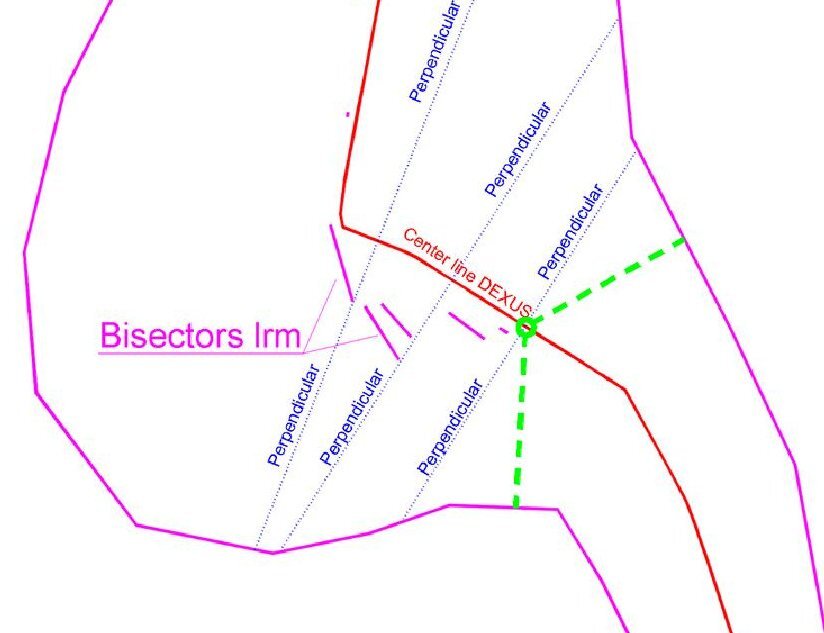
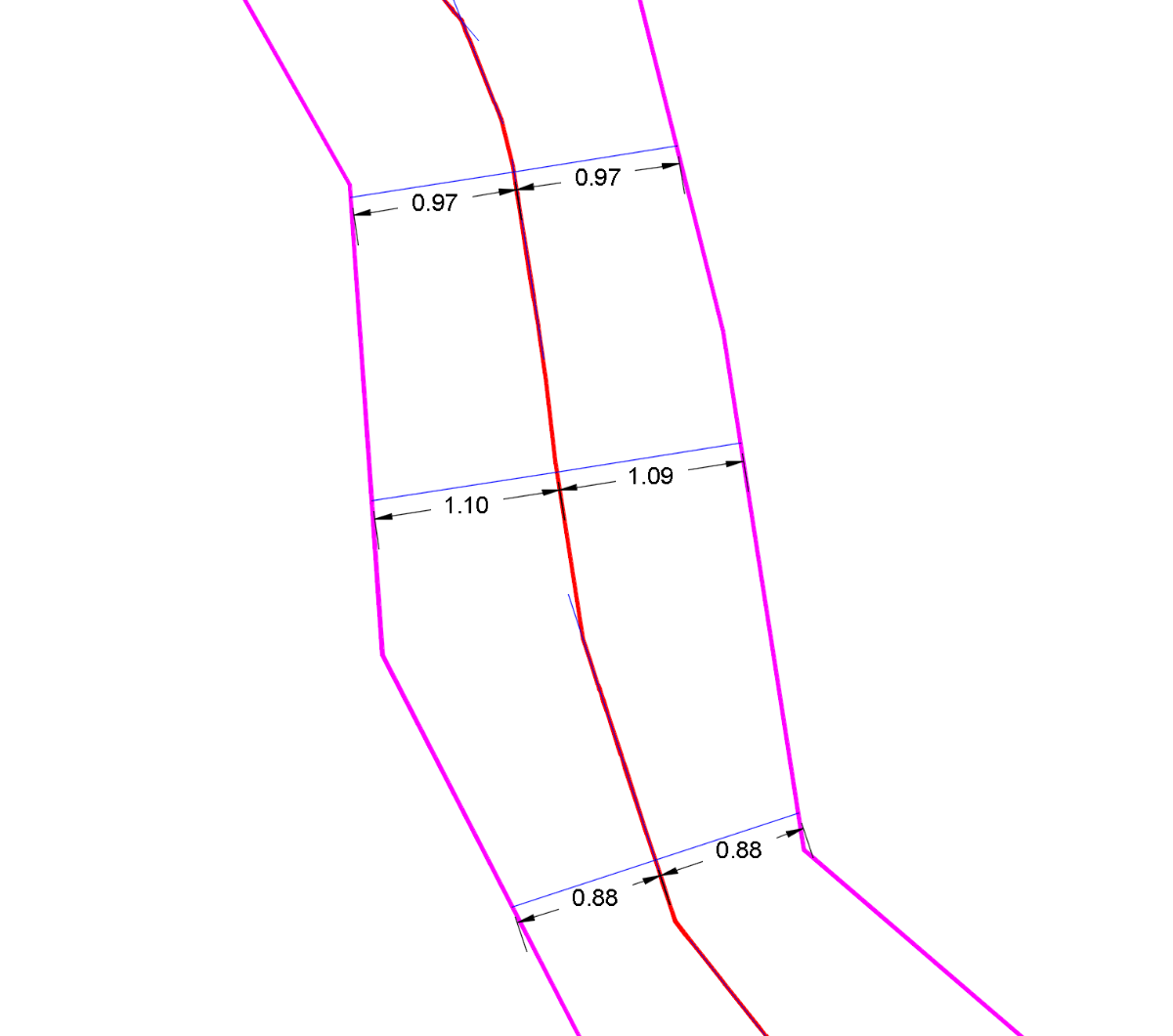
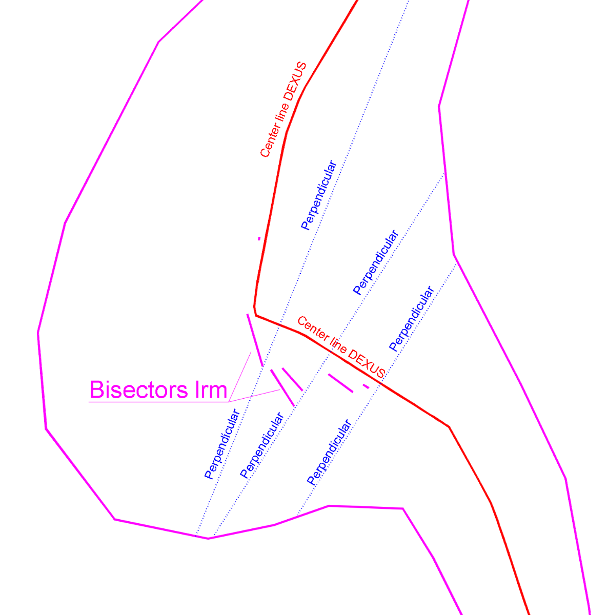
Hi, I’ve tested @dexus's code and it’s definitely the best one that has appeared so far. I only found a small discrepancy in one area where it seems that obtaining the correct centerline is actually possible (see the first image). Everywhere else, the centerline seems to have been achieved whenever it was geometrically feasible. One small point that might be improved is in the area where the margins widen (as shown in the second image). Although getting a truly equidistant centerline is impossible there, it might still be worth trying to ensure that the perpendiculars to the centerline hit each margin at distances that aren’t too different from each other. As you can see in the image, there’s a section of the centerline (near the point where it turns north) where the right margin falls outside the acceptable range. I think @lrm's bisectors give a good hint of the path the centerline should follow in order to avoid this.
-
AutoLISP: loop through selected objects and do something
BIGAL replied to Vittorio's topic in AutoLISP, Visual LISP & DCL
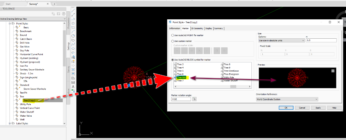
Rather than explode the COGO point what are you trying to do ? I have for example write the RL of a cogo point as text next to the point. We used this as a quick reference when designing, we would select only the points that we want to see the RL. It could be expanded to say label XYZ, PtXYZD etc. The tree block should be on the correct layer according to your Description key Sets. A side note it's possible to update a cogo point dynamic block, I have something that does just that, it looks at the description, so TR6*300, dynamic block has a trunk and spread 2 objects, running my lisp would get a 6m spread with a 300 mm trunk. @Steven P the COGO points in Civ3D are proxy objects. In a dwg if labels are off can not turn on in ACAD. I am looking at talking to Bricsys about getting at "AeccXUiLand.AeccApplication." when a civ3D dwg is opened in Bricscad. Getting at CIV3D objects via lisp can be easy or difficult. -
 quangtrung.utt joined the community
 -

AutoLISP: loop through selected objects and do something
Steven P replied to Vittorio's topic in AutoLISP, Visual LISP & DCL
Up load your LISP so we can have a look. I suspect you will want to explode the block and then use entlast select it ready to move it to the correct layer - that might be enough of a hint? Since you have the entity name, I would just use entmod to change the layer -

AutoLISP: loop through selected objects and do something
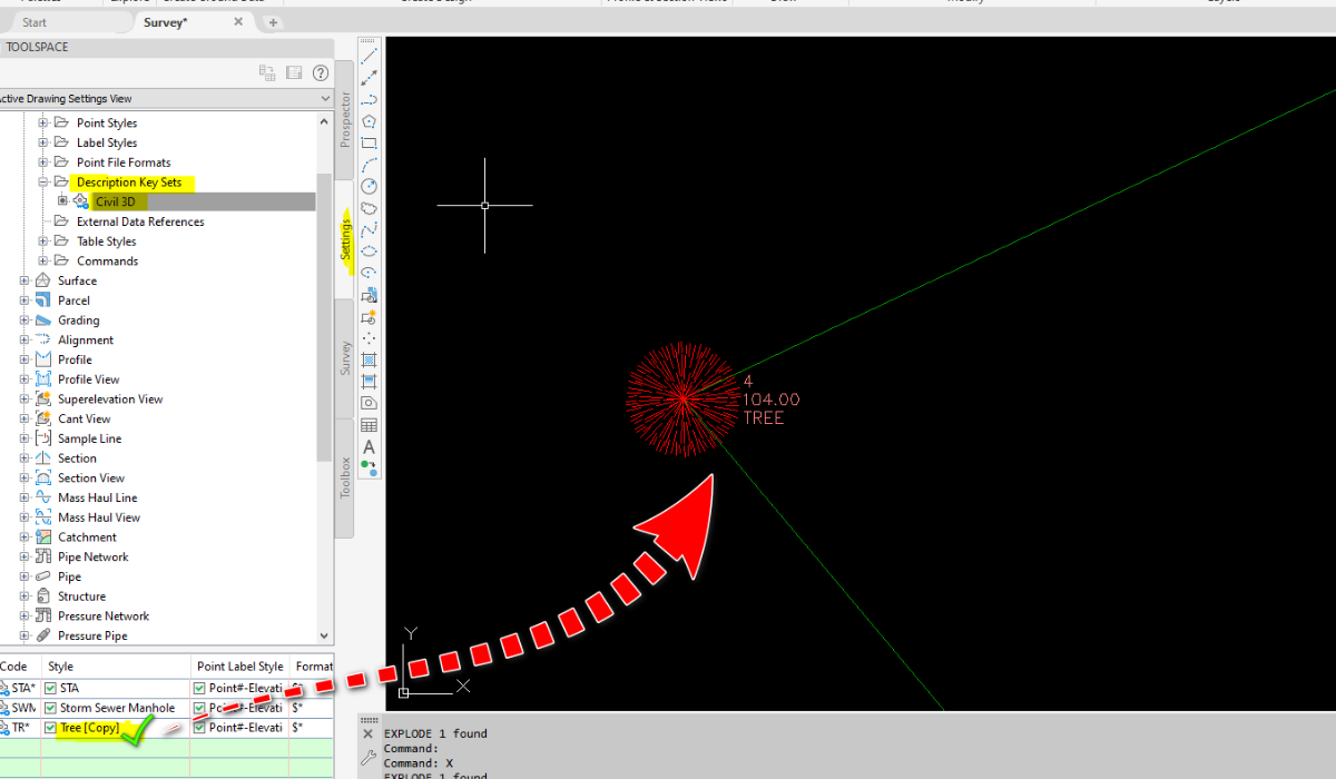
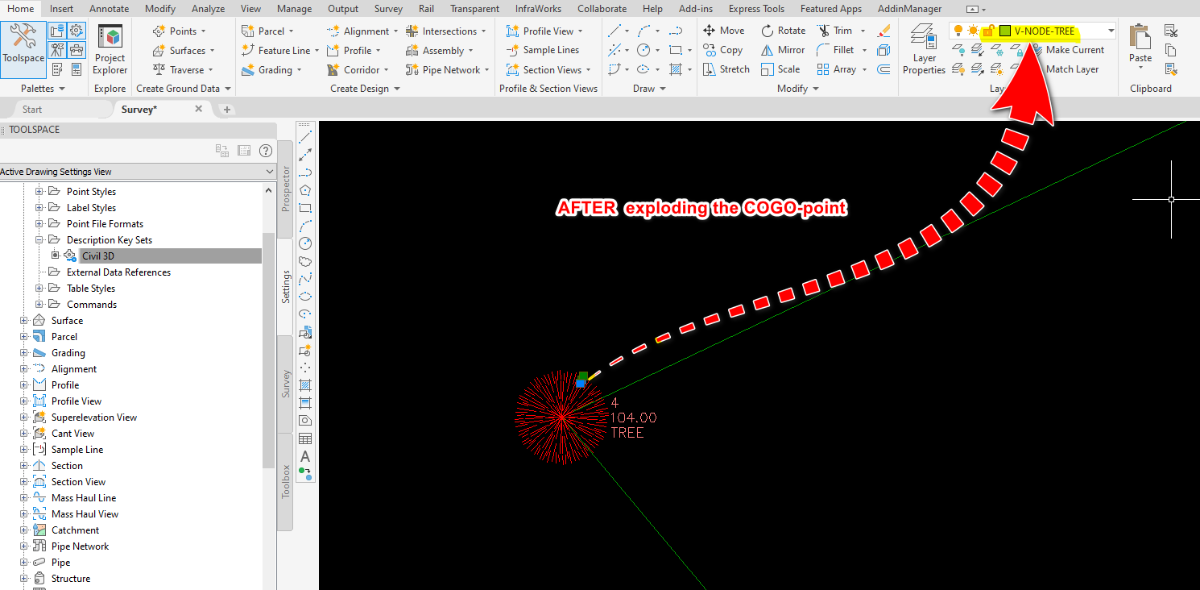
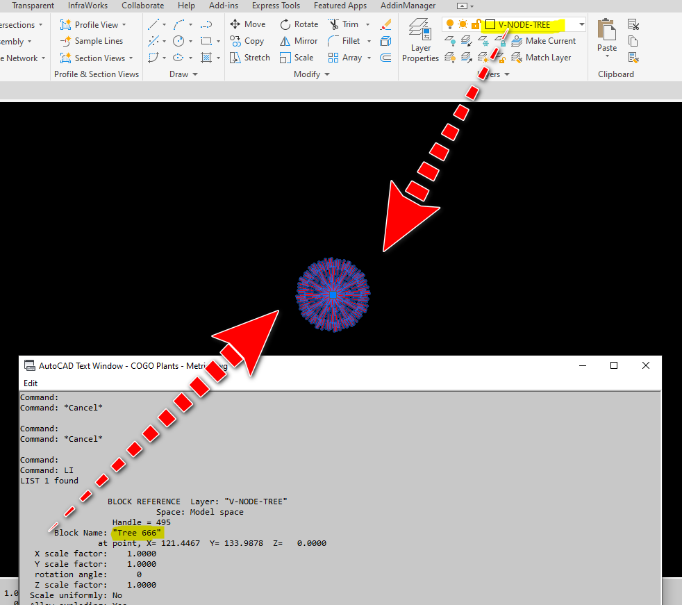
Vittorio posted a topic in AutoLISP, Visual LISP & DCL
Hi everyone, I'm currently trying to write a routine that handles multiple selected objects. In my drawing imported survey points are automatically stored as COGO-points with a specific point label style (a block reference defined by description sets). The problem is upon exploding the COGO-point (twice) it's layer is reverted to 0. Therefore I need a routine to change the layer back to the one defined by the corresponding description key. This routine should: prompt for selecting object(s) - COGO-points only for each COGO-point do the following store its layer to a variable (eg. "XX_TOPO_TREE") explode the COGO-point - which will result in a block reference with name *Uxxx (eg. *U123) explode the block - will result in a named block on layer 0 (eg. "sym_topo_tree") change the block layer to the one stored before After trying to teach myself AutoLISP over a year ago I almost forgot anything I've read due to a longer break. Now I am starting from the beginning again. Since it would take some time until I get this on my own, I hereby ask for a solution / a lisp routine. Best regards -
Yes Civil Site Design is a full Civil design package, Surfaces, Roads, Gradings, Drainage and Sewerage. It is sold world wide, in particular in available for CIV3D and Bricscad. They do a OEM Acad as well. https://civilsitedesign.com.au/ There is numerous YouTube videos showing features and how to's. https://www.youtube.com/@CivilSurveyApplications If you have a particular design task let me know I can make enquiries for you, but they are very helpful. I have known the Director for like 40 years so its a product that has that type of on going improvement history. It uses much more intelligent DCL's for data input than CIV3D. Look at the Youtubes.
-
Polyline Elevation Propertie in UCS
lrm replied to Oscar Fuentes's topic in AutoCAD 3D Modelling & Rendering
The polylines that are on planes that pass through the world point 0,0,0, will have an elevation of 0. Planes that do not include 0,0,0 will have a non zero elevation value. 92.8477 is the distance from the plane of the polyline to world 0,0,0 measured in a direction perpendicular to the plane. Review my previous post then try the following: Create a point at world 0,0,0 Create a UCS that contains the polyline that hast the 92.8477 elevation so that it is on the XY plane of the UCS. Select the point and note that it z coodinate is + or - 92.8477 -

Polyline Elevation Propertie in UCS
Oscar Fuentes replied to Oscar Fuentes's topic in AutoCAD 3D Modelling & Rendering
The image... -
Polyline Elevation Propertie in UCS
Oscar Fuentes replied to Oscar Fuentes's topic in AutoCAD 3D Modelling & Rendering
In the attached DWG file, a truncated pyramid was drawn with a unit of constants (UCS) on each face. The elevation of one of the polylines is 92.8477 and the other is 0.00, which does not correspond to the observations. UCS x Polyline problem1.bmp -
Polyline Elevation Propertie in UCS
lrm replied to Oscar Fuentes's topic in AutoCAD 3D Modelling & Rendering
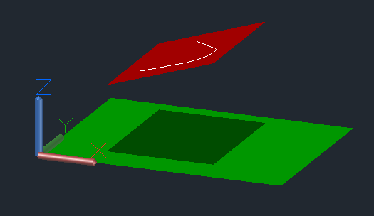
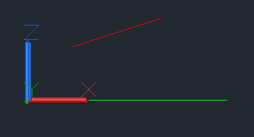
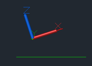
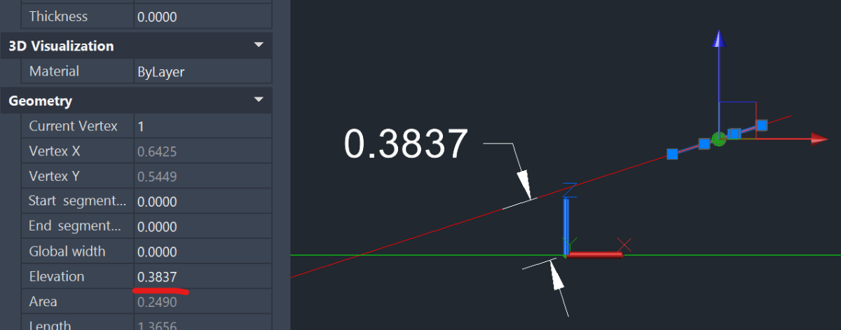
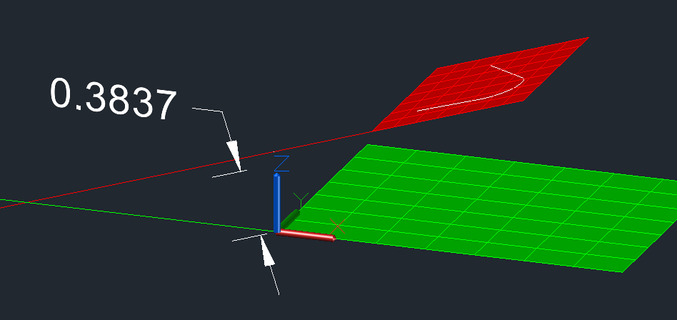
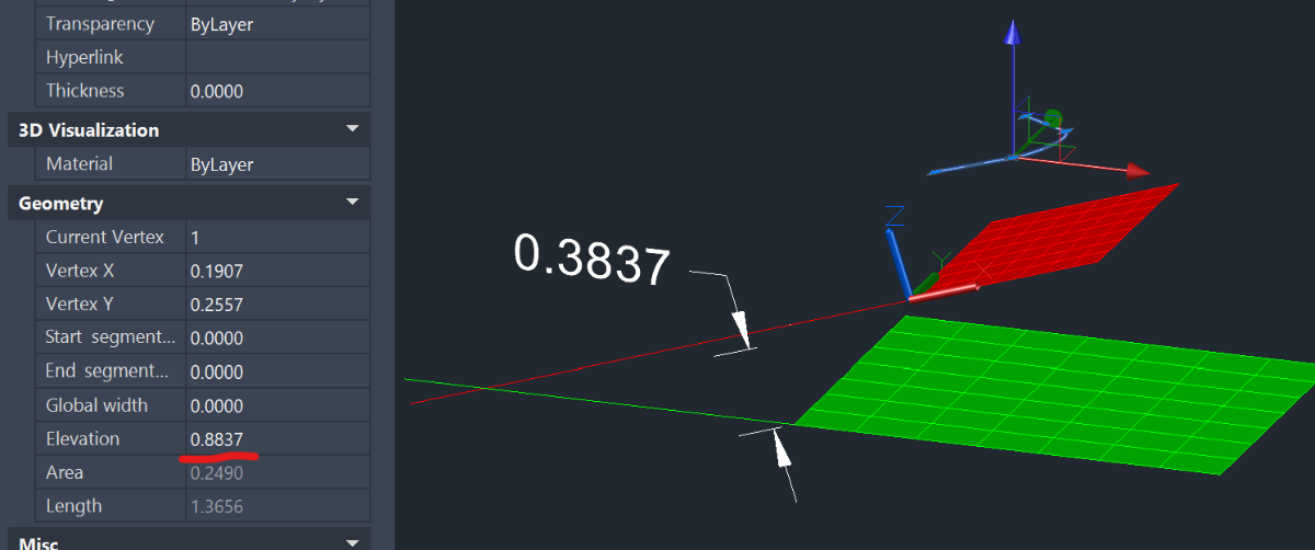
In the following image the green plane lies on the World XY plane while the red plane is above it and tilted. The white polyline was drawn on the red plane by setting the ucs so that it's Xand Y axes were coincident with it. Here's a front view with the World ucs active. Same view but with the UCS of the red plane active. The perpendicular distance from the plane of the polyline to World (0,0,0) is the polyline's elevation. Note that if the polyline is moved by 0.5 in the z direction of the red plane the elevation changes by 0.5. So the anser to the question "Can I change a polyline in my new coordinate system so that it has an elevation that conforms with the World system?" is, It Depends. The UCS of the polyline must be parallel to the world ucs but you would need to also make it coincident to the World UCS!