All Activity
- Past hour
-
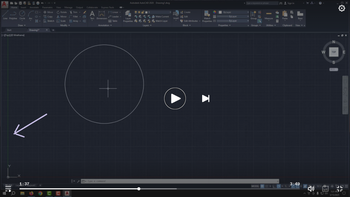
If that green line is the Y axis, it's not part of your drawing, it's part of the environment. Where and how it appears will depend on the local settings. That's probably why it looks different when you reopen the drawing. If you need that axis as part of your drawing, consider drawing a line there. At least then it will become part of the extents.
-
.thumb.jpg.615654602253be56b2fbd5d064834780.jpg)
Getting a 2D section from a 3D model
indiancad replied to indiancad's topic in AutoCAD 3D Modelling & Rendering
I was mainly thinking of SECTIONPLANE as a quick way to inspect a 3D model interactively. I wasn't considering the other section workflows such as SECTION, SOLVIEW, and VIEWBASE. Thanks for pointing that out — there are clearly several ways to approach sections depending on the drawing workflow. -

Why does a 3D solid become difficult to edit after using UNION?
SLW210 replied to indiancad's topic in AutoCAD 3D Modelling & Rendering
I use SOLIDEDIT tools, they work well for what AutoCAD actually is to be used for. There are lots of 3D modelling software and 3D CAD that is better at handling 3D model changes, but they all have pretty good learning curves. -
A 3D model can look perfect on screen and still contain small errors that cause problems during manufacturing.
SLW210 replied to indiancad's topic in AutoCAD 3D Modelling & Rendering
If you create the proper 2D views and provide all of the pertinent dimensions, any issues should come to light at that point. I usually double check the 3D model with actual Dimensions as well, often set to 8 decimal places as I am modelling. Sometimes (MEA)SUREGEOM is quite handy. - Today
-
How do you handle very small details in a 3D model?
SLW210 replied to indiancad's topic in AutoCAD 3D Modelling & Rendering
It was meant more as a polite unofficial warning than a "point' or feedback. Pertaining to "point", that brings up the question, what is your point in these posts? Asking a lot of questions, then not responding to those who have engaged the issue is generally seen as disrespectful and discourteous. -

Why does FILLETEDGE fail on some 3D solid edges?
ReMark replied to indiancad's topic in AutoCAD 3D Modelling & Rendering
An image might help. -
Why does FILLETEDGE fail on some 3D solid edges?
SLW210 replied to indiancad's topic in AutoCAD 3D Modelling & Rendering
Can you provide such a case? FILLETEDGE and FILLET seem to act as expected as best I have noticed, barring a mistake by the user. CHAMFER seems to make weird corners at times, but with both, you just need a logical selection order and learn to use LOOP and CHAIN options. -
Just post the drawing and people can stop guessing.
-
Getting a 2D section from a 3D model
SLW210 replied to indiancad's topic in AutoCAD 3D Modelling & Rendering
Do you have actual statistics on whether beginners use this feature very often? I actually used it a lot more long ago when I had a different type of work load, these days I don't need it as much. You can create a hatched section for your detail with SOLVIEW and VIEWBASE, so I am not so sure too many are drawing these manually. There is also SECTION. -
One useful feature I don't see beginners using very often is SECTIONPLANE . Instead of manually drawing the internal edges of a 3D part, you can place a section plane through the model and use Live Section to inspect the inside. You can then generate a section block from the result for use in a drawing. I find this especially useful when checking what is actually inside a complicated 3D model before creating the final 2D documentation.
-
 FMA joined the community
 -
 Anindita joined the community
 - Last week
-

How do you handle very small details in a 3D model?
BIGAL replied to indiancad's topic in AutoCAD 3D Modelling & Rendering
@SLW210 yes lots of posts maybe need a "How do you" sub section. Maybe all posts should be in the "Autocad Beginners Area". -
Maybe this UCSORG set origin point to say a object point. UCSICON ON will display corner icon for current UCS.
-
Why does a 3D solid become difficult to edit after using UNION?
indiancad replied to indiancad's topic in AutoCAD 3D Modelling & Rendering
You're so welcome! It’s one of those things where having a few different workflows in your back pocket makes a huge difference, especially when a Boolean operation doesn't quite give you what you expected. -
Why does FILLETEDGE fail on some 3D solid edges?
indiancad replied to indiancad's topic in AutoCAD 3D Modelling & Rendering
Yeah ! but I was referring more to cases where the operation still fails despite adjusting the radius, particularly around complex geometry. I also see your point about using FILLET for regular edges. Thanks for the clarification. -
How do you handle very small details in a 3D model?
indiancad replied to indiancad's topic in AutoCAD 3D Modelling & Rendering
I understand your point. I can see that my posts have been repetitive in style, and I apologise for that. I'll take more care to contribute genuine experiences and useful technical information rather than creating similar discussions. Thank you for the feedback. -
Why does LOFT sometimes twist or fail unexpectedly?
indiancad replied to indiancad's topic in AutoCAD 3D Modelling & Rendering
I apologize for this and I can see how my repeated posts have come across as repetitive and spam-like. That wasn't my intention, but I understand the concern. I'll stop creating new threads for now and be much more careful about checking existing discussions before posting again. and thanks for pointing this out. -
Before sharing a model, I find it useful to check critical dimensions with MEASUREGEOM, inspect the part from multiple views, and verify that the geometry is suitable for the intended process. A visual check alone may not catch every issue. What checks do you normally perform before releasing a 3D model for manufacturing?
-
 Teduap joined the community
 -
 DPE4JC joined the community
 -
 anfinton254 joined the community
 -
Using the folding grip in notepad++ does work. However you cannot select that way on any line, only the one with a grip. So the AHK routine, does not break any of the native N++ shortcuts and let you highlight any code or portion of code as long as it is between brackets. (Brackets ( ), { }, [ ] ) ymg
-
Looks like your 1st dwg might not be in plan and 2d wire view. Try this sequence of command: _.VSCURRENT 2 _.Plan _W
-

Lisp Code for transforming list number to numbered block?
dber replied to dber's topic in AutoLISP, Visual LISP & DCL
This looks amazing! Thank you so much! I did notice a couple random multi-line blocks were placed on the 1st line, but other than that this is amazing!
-
that is green line , after zoom Extents application , this shows away from ucs ( y-axis ). what to do to solve it ?
-
Yes, that's right, in this case it's a car roof that needs to be made without defects. I have been using Solidworks relatively recently, I am not a professional, but I am interested in 3D modeling and I want to develop in this. I decided to contact the forum because this is not the first time I have encountered the problem of creating and controlling just such a form (examples p1.jpg, p2.jpg) and I have not been able to understand how such a form can be made without defects. In this case, the roof has a shape: D1.jpg, mesh v2.The SLDPRT is based on this drawing, but as I now understand it, this construction approach is not correct. The video presents how I understand polygonal modeling. I would like to understand how this form can be done in the classic Solidworks approach
-
green line is line of y-axis of ucs , it is not a separate object. i have to bring this view in a form as that of new drawing, where green line ( of ucs ) is normal,
-
See if it makes a difference if you completely docked the command prompt instead of having it floating at the bottom
-
What's the "green line"? Hard to tell anything from an image. Please explain better or post the .dwg.