All Activity
- Today
-

My drawing disappeared — what do you check first?
BIGAL replied to indiancad's topic in AutoCAD 2D Drafting, Object Properties & Interface
My $0.05. ZOOM E zoom c (getvar 'extmax) 100 May need a different scale than 100 If ok then zoom c (getvar 'extmin) 100 -
 EduLos joined the community
 -
.thumb.jpg.615654602253be56b2fbd5d064834780.jpg)
My drawing disappeared — what do you check first?
indiancad posted a topic in AutoCAD 2D Drafting, Object Properties & Interface
Have you ever opened a DWG and suddenly thought, “Where did my drawing go?” The objects may still be there, but they could be far from the current view, on a turned-off layer, or hidden inside another location. Here are a few quick things I usually check: Zoom Extents to see if the drawing is just far away from the current view. Layer visibility (make sure layers are not frozen or turned off). Check if objects are on a hidden or locked layer. UCS / View settings in case the view is rotated or shifted. Drawing units & scale to ensure objects aren’t extremely small or large. Use SELECT ALL to confirm objects still exist in the file. I usually start with Zoom Extents first, then move through the rest. I usually start with Zoom Extents first, then move through the rest. What do you check first when your drawing suddenly disappears? - Yesterday
-

AutoCAD Layer Properties Manager Tools: Tuesday Tips With Frank
The AutoCAD Blog posted a topic in AutoCAD Blogs
It’s time to revisit the Layer Properties Manager Palette. There are so many things to discuss in this palette, many of which are overlooked. From our training days to our daily work, we’re generally focused on the table of layers and properties. Oh, but there’s so much more. Previously in this blog, I’ve discussed the tools found to the left of the table. One was about creating and using Layer Filters, and then another about Layer States (links included for your convenience). Today’s post focuses on the columns of the table. I’m again using the Floor Plan sample file and in a Layout Tab so that all of the VP columns are displayed. Property Column Tools By default, the layer property columns appear as they do in the image below. They appear condensed and generally hard to read. You’ve probably already figured out that you can sort the table in an ascending or descending manner based on a column. Simply click that column header (as shown below) to sort. The up or down arrow will be your visual cue. Also, double-clicking on the right edge of a column will expand that column to its optimized state. I’ll get back to what that means in a moment, but again, the animation below shows it in action. The Right-Click Menu That last nugget is indeed handy, but in a layout view, there are 19 columns – hardly an efficient way to handle the task. That’s where the right-click menu comes in. Just hover over any column header and right-click. You’ll be presented with the menu as shown in the following image. In the top and bottom sections, you’ll see each column with a check mark beside it, indicating it’s displayed (the bottom VP columns won’t appear in Model Space). Don’t need a property column? Turn it off by clicking on the name. Are you a CTB office? If so, the Plot Style column just takes up space, so you can turn it off here. Let’s turn our focus to the middle section of the menu. Here, we have tools to Maximize or Optimize all columns, or only the one you right-clicked on. What’s the difference? Maximize changes the width of all columns to fit the column headers and the data content. Optimize changes the width of all columns to fit the content in each column. You can see the effect of each in the image below. Below these four tools is one more that is labeled as either Freeze or Unfreeze column. Please note that with this command, it does matter which column header you right-clicked on, so keep that in mind. Also note that by default, the Status and Name columns are frozen. What does this mean exactly? Freeze keeps the column, and any columns to the left, visible while scrolling. Unfreeze it so that all columns scroll. Let’s say I need to see the On and Frozen status while I’m way off in the far right side of the palette. The animation below will show you the workflow and the results. That’s a lot of power, and since these tools aren’t used all the time, you might forget about what they do exactly and royally mess up your palette. Don’t worry, there’s also a restore all to default tool for just such an occasion. There’s just one more tool on the right-click menu. You may have noticed one called Customize… right below the standard column names. Clicking it will display the dialog shown below. Now, here at Tuesday Tips HQ, we pride ourselves on minimizing picks and clicks. My tip for you then is to use the method described above to display your desired columns. Otherwise, you’re just adding unnecessary clicks to your workflow. I guess if you wanted to turn off multiple columns at once, this would be more efficient, as the right-click menu dismisses once you select one to display or not, but since I’ve never done that in my four decades of using AutoCAD, I doubt you will either. Or I might be wrong – that I do know that I’ve done in that time frame. Until Next Time It’s not unlikely that I’ll see you again in the future with even more AutoCAD Layer Properties Manager tips, as there’s a lot of functionality in there. Meanwhile, don’t forget to review the Layer Filters and Layer States tips. There’s a lot there that can improve your overall efficiency. More Tuesday Tips Check out our whole Tuesday Tips series for ideas on how to make AutoCAD work for you. The post AutoCAD Layer Properties Manager Tools: Tuesday Tips With Frank appeared first on AutoCAD Blog. View the full article -

Does anybody else have this DIMBREAK issue?
SLW210 replied to SLW210's topic in AutoCAD Bugs, Error Messages & Quirks
DIMBREAK>Remove works but is tedious, then I have to rebreak them. Still stumped on what caused this in these drawings, not all of the dimensions with DIMBREAKs froze like this. I came up with a LISP to remove all DIMBREAKs in a drawing, now I just need redo the dimensions that need breaks. Also, I believe all of the dimensions with issues were broken by an object, those that were not having issues were broken by other dimensions. - Last week
-
Does anybody else have this DIMBREAK issue?
SLW210 posted a topic in AutoCAD Bugs, Error Messages & Quirks
I have some drawings with issues with DIMBREAK. While working in the drawing and creating the dimensions, then breaking them, I have no issues, but after saving and closing then opening these drawings I did a few weeks ago and modifying, moving, deleting objects that break the dimension, the gaps remain. So far it's just been these few drawings I am modifying, I haven't reproduced the issue yet. Probably a long shot that it's happened to anybody else, but it has me stumped as to how this happened. I have just created new dimensions and all is fine now. I guess just a weird fluke. DIMBREAK Issue R14.dwg DIMBREAK Issue.dwg
-

Generating a Profile for a 147km Project
CyberAngel replied to Butterstone's topic in Civil 3D & LDD
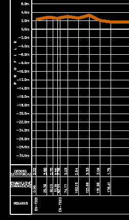
I've done this before, when I had centerline elevations but not much else. Import the points. Connect them with a polyline (the CNCPT command may help). This polyline will be helpful in the next step, so don't erase it when you create your alignment. Offset the centerline (that polyline we talked about) about two feet. Connect one end, Join it to the sides, and Close the polyline so you have a border. Create a surface using your points and that border. Define a profile with the new surface and the alignment. When you have styles for the profile view and the labels the way you want them, add them to a template so you don't have to go through that process again. Edit: Sorry, the CNCPT command is a third-party product, i.e. it costs money. That was the first result from Goggle. You can use the 'PN command instead (don't forget the quote) if your points are numbered to match the progress of the path. -
Azimuth and Distance with Drawn out Leaders Dimensioning on Civil 3D 2018
CyberAngel replied to Butterstone's topic in Civil 3D & LDD
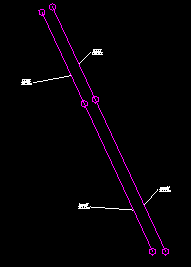
You can create a label style that looks like what you want. You can use Annotation | Add Multipurpose Labels | Multiple Segment to create labels, all at once, for every segment of a polyline. How you drag them away from their segments, I don't know. Maybe isolate them and use the stretch command on a linear bunch at a time. -
 SionCV joined the community
 -
Reload LineTypes in AutoCAD 2027 not working?
SLW210 replied to Aftertouch's topic in The CUI, Hatches, Linetypes, Scripts & Macros
So instead of fixing this issue, there's a workaround. Thanks for getting back! -

Reload LineTypes in AutoCAD 2027 not working?
Aftertouch replied to Aftertouch's topic in The CUI, Hatches, Linetypes, Scripts & Macros
Feedback from Autodesk: https://www.autodesk.com/support/technical/article/caas/sfdcarticles/sfdcarticles/Complex-linetype-still-shows-shape-symbols-after-reload-in-AutoCAD-2025-and-later.html -
 rush77 joined the community
 -
 goldberg joined the community
 -
Azimuth and Distance with Drawn out Leaders Dimensioning on Civil 3D 2018
BIGAL replied to Butterstone's topic in Civil 3D & LDD
Post a sample dwg. CIV3D has a lot of labelling stuff, usually though have to move the label when applied automatically, you may need a custom lisp. There is maybe label Pline legs lisp out there but they would be parallel to each leg. Search Kent Cooper forums/autodesk pretty sure he has something. -
A couple of ways to achieve this as it sounds like you only have the single Profile points, you can make a pline of the points ie XYZ, copy that pline left and right, you can use the points to make a TIN, using the central pline as an Alignment you can walk along the pline and make your Long section using the normal CIV3D road plot commands.
-

Beyond APPLOAD: A local script manager for those of us with too many LISPs
VicoWang replied to VicoWang's topic in AutoLISP, Visual LISP & DCL
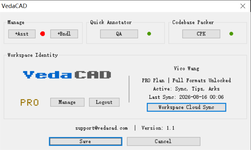
Hi zaphod, Thank you for your suggestion. I have updated the function of [Automatically populate the asset name from the file name] to version 1.1. You can check the update in the client, or download the latest version directly on our official website ( https://www.vedacad.com ) to replace it. Thank you again for your suggestion. -
VedaCAD - Technical Support, Updates & Community VCIDs
VicoWang replied to VicoWang's topic in AutoLISP, Visual LISP & DCL
v1.1 Aug 16, 2026 Download link: https://www.vedacad.com - Auto-filling Asset Name from File Name (Thanks to zaphod's suggestion) - Enhanced Network Stability - Fix known bugs
-

Testing DWG compatibility with different CAD applications
Danielm103 replied to indiancad's topic in Catch All
BricsCAD and others can manipulate dynamic blocks created with AutoCAD, if you use/purchased the software outside of the US. Gemini says the core patent expires in April 2027. I don’t think the intellicads will have the grips and bedit ready by then, maybe. You probably could roll some utilities for some common blocks, with lisp/python/etc to make changes, I.e. visibility -
Testing DWG compatibility with different CAD applications
SLW210 replied to indiancad's topic in Catch All
One more question. From what CAD platform did the tested drawing originate? Only AutoCAD can successfully manipulate Dynamic Blocks created with AutoCAD as they have a patent on theirs and others just try to have Advanced Blocks. I gathered this information, not sure if relevant to the most current releases of IntelliCAD products... -
Azimuth and Distance with Drawn out Leaders Dimensioning on Civil 3D 2018
SLW210 replied to Butterstone's topic in Civil 3D & LDD
Welcome to CADTutor! -
I have moved your thread to the Civil 3D & LDD Forum, please post your Civil 3D questions in this forum.
-
Dear All, Excited to join this Forum. I would appreciate guidance on how to achieve the below for a 147km Topographical Survey Project. I want to generate a Profile in civil 3d 2018. I have a center line with elevations along the line at 24-25m intervals. I also have the CSV file with the Eastings and Northings coordinates of each of the points The process should be automatic.. I have attached an image of what the profile should look like. Your help is appreciated. Thank You.
-

Azimuth and Distance with Drawn out Leaders Dimensioning on Civil 3D 2018
Butterstone posted a topic in Civil 3D & LDD
Dear All, Excited to join this Forum. I would appreciate guidance on how to achieve the below for a 147km Topographical Survey Project. I want to Auto Annotate a polyline in civil 3d 2018 with Azimuth bearing showing only degrees and minutes and distance with a leader and arrow head pointing to each segments between points, but with the leader line drawn away from the line as shown on the attached image using civil 3d and i want azimuth and distance split into two stacked lines separated by a divider? The process should be automatic when I click the Polyline, so i don't have to manually click each segment. I have attached an image of what it should look like. Your help is appreciated. Thank You. 14:30 To achieve this automa
-
Butterstone joined the community
-
 tariq9835 joined the community
 -
VedaCAD - Technical Support, Updates & Community VCIDs
VicoWang replied to VicoWang's topic in AutoLISP, Visual LISP & DCL
TIPS: Why is VedaCAD called a modern CAD package management tool? As a developer or curator, you can publish your plugins on the client side, or combine plugins from other developers into a professional bundle for sharing. The web dashboard will provide statistics and displays for these plugins or bundles, allowing you to accurately grasp each asset's downloads. You no longer need to guess whether anyone is using your tools. Your web dashboard will provide you with precise, real-time telemetry data: global download volume, physical device installations, and most importantly—how many enterprises have officially adopted your VCID as their corporate standard, among other data metrics. Even for free-tier users, the web dashboard is fully provided. -

Updated AISC Shapes for STL.LSP
Carlos Melchor replied to gtwatson's topic in AutoLISP, Visual LISP & DCL
Buenas tardes Catascuro, estuve revisando sus archivos y están interesantes, se agradece por el aporte. Una consulta el archivo indica 2013, su actualización fue en el 2024?. Gracias -
Carlos Melchor joined the community
-
 mathjunkie joined the community
 -
Testing DWG compatibility with different CAD applications
SLW210 replied to indiancad's topic in Catch All
I did see where ActCAD was on release 14.1 and would expect that may be the case with CMS. CMS released 14 about 1 year ago, so maybe the latest updates may come here shortly. Some of the prices to join the IntelliCAD consortium see a bit steep, you would have to sell a lot of seats to get your fee and cover your own cost to create a program and break even much less a profit. Kudos to the companies having a good price. It seems Carlson Survey, Leica, and some others are on IntelliCAD. I'll try to start in the coming days doing a little dabbling and comparing. I plan to actually do real testing and maybe a Pro/Con review, I'll see how my time goes. -
Testing DWG compatibility with different CAD applications
Danielm103 replied to indiancad's topic in Catch All
Oh cool! I think down stream members are still on 14.1. I’ll have to kick the tires on CMS, or maybe ACTCAD once the update. I have not seen C++ SDKs for ACTCAD\ CMS uses the same version numbers -
When Should You Use Blocks, XREFs, and Overlays in Large CAD Projects?
indiancad posted a topic in Catch All
In larger CAD projects, performance and drawing organization often depend more on how external content is structured than on the number of objects in the drawing. Consider a typical building project where the architectural, structural, electrical, and mechanical teams are working on separate DWG files. The architectural floor plan is referenced into the MEP drawings, structural backgrounds are updated regularly, and several common elements such as title blocks, grids, and standard details are reused across multiple sheets. As the project progresses, revisions can quickly lead to multiple levels of XREFs and nested references. At that point, the choice between a block, XREF Attachment, or XREF Overlay can have a noticeable impact on coordination, file dependencies, and drawing performance. I’m interested in how experienced CAD users approach this in real projects: For a large multi-discipline project, what is your preferred strategy for keeping the drawing structure predictable, maintainable, and easy to troubleshoot as the project evolves? -
Testing DWG compatibility with different CAD applications
SLW210 replied to indiancad's topic in Catch All
They look very promising for a CAD alternative that can be upgraded with LISP, et al. I believe there is a list of CAD products that use IntelliCAD on their website. IntelliCAD® Technology Consortium: The intelligent alternative for CAD developers Here is the latest IntelliCAD update, though it would be nice to know which update the CAD Packages are using, maybe can be found on the individual websites. IntelliCAD 15.0 Release Details