All Activity
- Past hour
-

How to copy an object to a specified distance
BIGAL replied to sinergy2020's topic in AutoCAD Beginners' Area
Like @CyberAngel if you set your osnap to what you want then type "Osmode" a number will appear that is current osnaps settings. Ok part two in say chx you can add this code. Note 1 is End. 0 is off. Normal drafting for me is 47. Try it (setvar 'osmode 47) then type osnap. For say a circle use 4. put at start (setq oldsnap (getvar 'osmode)) (setvar 'osmode 1) .... code put at end (setvar 'osmode oldsnap) -

Add to the code the ability to create layouts for non-standard formats
Nikon replied to Nikon's topic in AutoLISP, Visual LISP & DCL
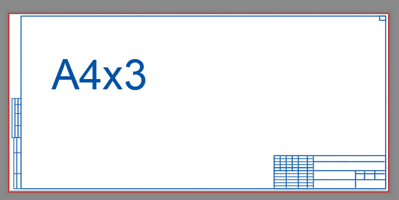
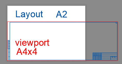
The layout is created correctly for this non-standard format. ((and (> Square 177755) (< Square 196466)) (vla-put-ConfigName Layout "DWG To PDF.pc3") (vla-put-CanonicalMediaName Layout "UserDefinedMetric (297.00 x 630.00мм)")) For this non-standard format (А4х4), the layout is set to A2_(594.00_x_420.00_MM), since the squares are the same (249480 и 249777), and therefore, the format that was previously written in the code is set. ((and (> Square 237006) (< Square 261954)) (vla-put-ConfigName Layout "DWG To PDF.pc3") (vla-put-CanonicalMediaName Layout "ISO_full_bleed_A2_(594.00_x_420.00_MM)")) ; А2 594.00x420.00=249480 ((and (> Square 237288) (< Square 262266)) (vla-put-ConfigName Layout "DWG To PDF.pc3") (vla-put-CanonicalMediaName Layout "UserDefinedMetric (297.00 x 841.00мм)")) ; А4х4 297.00x841.00=249777
-
Add to the code the ability to create layouts for non-standard formats
BIGAL replied to Nikon's topic in AutoLISP, Visual LISP & DCL
If you look at this snippet of code it is all the values required, insert correct title block and make a viewport. This is for one viewport, multiple title blocks. (cond ((= ntitle "A0_Landscape") (setq ht 780.0 wid 1160.0 xpt 878.0 xwid 62.0 yht 32.0)) ((= ntitle "A1_Landscape") (setq Ht 541.0 wid 831.0 xpt 542.0 xwid 62.0 yht 32.0)) ((= ntitle "A1_Portrait") (setq Ht 774.0 wid 571.0 xpt 229.0 xwid 62.0 yht 32.0)) ((= ntitle "A2_Landscape") (setq ht 367.0 wid 584.0 xpt 295.5 xwid 62.0 yht 32.0)) ((= ntitle "A2_Portrait") (setq ht 554.0 wid 410.0 xpt 209.5 xwid 41.0 yht 23.0)) ((= ntitle "A3_Landscape") (setq ht 247.0 wid 400.0 xpt 200.0 xwid 41.0 yht 23.0)) ) So for multiple viewport the cond would use a "list" of values, title block then the viewport say lower left X,Y then upper right X,Y, repeat for how many viewports required. You could pick correct title block from a dcl radio button you can have around 20 in vertical dcl. If I am understanding correct post a true title block with say 3 viewports and will post some sample code, -

How to copy an object to a specified distance
sinergy2020 replied to sinergy2020's topic in AutoCAD Beginners' Area
Thanks again @CyberAngel I just realized that I didn't check the boxes of the different snap settings - Today
-

Understanding 'Getenv Variable call denied'?
pkenewell replied to ScottMC's topic in AutoLISP, Visual LISP & DCL
@ScottMC I don't recommend you put the OSMODE change in the CMDACTIVE loop. Here is how I would do it; tested this and it works perfectly. (defun c:C2 (/ cr el *error* fp oe os p p2) (defun *error* (msg) (if oe (setvar "cmdecho" oe)) (if os (setvar "osmode" os)) (vla-endundomark (vla-get-activedocument (vlax-get-acad-object))) (princ (strcat "\n" msg)) ) (vla-startundomark (vla-get-activedocument (vlax-get-acad-object))) (setq oe (getvar "cmdecho") os (getvar "osmode") ) (setvar "cmdecho" 0) (while (and (setvar 'osmode (boole 7 os 512)) (setq fp (getpoint "\nSpecify 1st Point of 2P.Circle: ")) ) (command "._Circle" "_2P" "_non" fp "_per");; Add "PER" to overide OSNAP here. (princ "\nSecond Point: ") (while (= (logand (getvar "cmdactive") 1) 1) (command pause) ) (setvar "osmode" os) (setq el (entget (entlast)) p (trans (cdr (assoc 10 el)) (cdr (assoc 210 el)) 1) p2 (getvar "lastpoint") cr (getvar "circlerad") ) (entdel (entlast)); Delete the Circle (princ (strcat "\n Coordinates: " (setq C2:pp ;; Global Variable "C2:pp" (strcat (rtos (car p) 2 4) "," (rtos (cadr p) 2 4) "," (rtos (caddr p) 2 4) ) ) "\n Diameter: " (rtos (* cr 2) 2 4) " | Radius: " (rtos cr 2 4) "\n" ) ) (entmakex (list (cons 0 "POINT") (cons 10 p))) (entmakex (list (cons 0 "POINT") (cons 10 p2))) (entmakex (list (cons 0 "CIRCLE") (assoc 10 el) (assoc 8 el) (assoc 40 el))) ; Recreate the Circle ) (setvar "cmdecho" oe) (vla-endundomark (vla-get-activedocument (vlax-get-acad-object))) (princ) ) If you don't want PERP to be the only snap available, then try your method, but before the CMDACTIVE loop: (command ".circle" "2p" 1st) (setvar 'cmdecho 1) (setvar 'osmode (boole 7 (getvar 'osmode) 128)) ;; added 'perp (while (= 1 (logand 1 (getvar 'cmdactive))) (command "\\") ) -
 mitiamak joined the community
 -

How to copy an object to a specified distance
CyberAngel replied to sinergy2020's topic in AutoCAD Beginners' Area
According to the NanoCAD web site, there is a snap option (OSNAP) that works like AutoCAD's. The endpoint snap ought to pick up the corners of a rectangle, unless there's something weird about NanoCAD's rectangle. Assuming you can snap onto the bottom right corner of the existing rectangle, you should be able to give a displacement from there to the bottom left corner of the new rectangle. That seems to be what you want. The whole point of snap mode is to give you an exact location based on an object, not on your closest pick point. Is it possible that you have a grid option enabled at the same time? That would explain why you can't always snap to an object, if there are grid intersections all around it. According to NanoCAD again, there is a "Snap and Grid" tab in the Drafting Settings dialog. Disable the grid snap and see what happens. -
 norad joined the community
 -
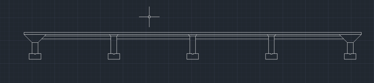
I'm assuming you created what is shown in the image above. You need to show the drain above the footing, the steel reinforcing rods, or rebar, as they are referred to in the concrete footings and columns, the baseplate at the foot of the columns, the columns themselves, etc., etc., etc. There are other threads about this project, in this forum, that contain word descriptions along with images that should prove useful to you. I suggest you research them as duplicating all that information here would be counterproductive.
-
 aniruddharaste changed their profile photo
 -
Add to the code the ability to create layouts for non-standard formats
Nikon replied to Nikon's topic in AutoLISP, Visual LISP & DCL
Thank you, is it possible to write this in the code so that the layout parameters are obtained automatically. I didn't understand this line: ("A3" "0,20" "140,190" "140,20" ""280,190" -
aniruddharaste joined the community
-
 cccc joined the community
 -

Hello everyone! Please take a look at this.
yangguoshe replied to sd2006's topic in AutoLISP, Visual LISP & DCL
(defun rh:dxf (code lst) (cdr (assoc code lst))) (defun c:aa ( / cmde ent e_typ e_lst area vtx x_lst y_lst z_lst x_pt y_pt z_pt c_lst v_lst ss sum sz) (cond ( (/= 0 (getvar 'cmdecho)) (setq cmde (getvar 'cmdecho)) (setvar 'cmdecho 0) ) ) (while (setq ss (ssget "_+.:E:S" '((0 . "POLYLINE,LWPOLYLINE") (-4 . "<OR") (70 . 1) (70 . 3) (70 . 5) (-4 . "OR>") ) )) (setq ent (ssname ss 0) e_typ (rh:dxf 0 (setq e_lst (entget ent))) area (getpropertyvalue ent "area") v_lst nil ) (cond ( (= e_typ "POLYLINE") (setq ent (entnext ent) vtx (rh:dxf 10 (entget ent)) ) (if (< (length vtx) 3) (setq vtx (reverse (cons 0.0 (reverse vtx))))) (while (/= "SEQEND" (cdr (assoc 0 (entget ent)))) (setq v_lst (cons vtx v_lst) ent (entnext ent) vtx (rh:dxf 10 (entget ent)) ) (if (< (length vtx) 3) (setq vtx (reverse (cons 0.0 (reverse vtx))))) ) (setq x_pt (/ (apply '+ (mapcar '(lambda (x) (car x)) v_lst)) (length v_lst)) y_pt (/ (apply '+ (mapcar '(lambda (x) (cadr x)) v_lst)) (length v_lst)) ) (if (= (setq sum (apply '+ (mapcar '(lambda (x) (caddr x)) v_lst))) 0.0) (setq z_pt 0.0) (setq z_pt (/ sum (length v_lst))) ) ) ( (= e_typ "LWPOLYLINE") (setq z_pt (rh:dxf 38 e_lst)) (foreach pr e_lst (if (= (car pr) 10) (setq v_lst (cons (cdr pr) v_lst))) ) (setq x_pt (/ (apply '+ (mapcar '(lambda (x) (car x)) v_lst)) (length v_lst)) y_pt (/ (apply '+ (mapcar '(lambda (x) (cadr x)) v_lst)) (length v_lst)) ) ) ) (setq c_lst (list x_pt y_pt z_pt)) (if(not sz) (progn (vla-getboundingbox (vlax-ename->vla-object ent) 'MinPT 'MaxPT) (setq p1 (vlax-safearray->list MinPT) p2 (vlax-safearray->list MaxPT)) (setvar 'textsize (* 0.05 (distance p1 p2))) (setq sz t) ) ) (entmakex (list (cons 0 "MTEXT") (cons 100 "AcDbEntity") (cons 100 "AcDbMText") (cons 10 c_lst) (cons 40 (getvar 'textsize) ) (cons 71 5) (cons 72 5) (cons 1 (strcat (rtos (/ area 1000000.0) 2 2) "m\U+00B2")) ) ) ) (if cmde (setvar 'cmdecho cmde)) ) -
Hello everyone! Please take a look at this.
yangguoshe replied to sd2006's topic in AutoLISP, Visual LISP & DCL
(defun rh:dxf (code lst) (cdr (assoc code lst))) (defun c:aa ( / cmde ent e_typ e_lst area vtx x_lst y_lst z_lst x_pt y_pt z_pt c_lst v_lst ss sum) (cond ( (/= 0 (getvar 'cmdecho)) (setq cmde (getvar 'cmdecho)) (setvar 'cmdecho 0) ) ) (while (setq ss (ssget "_+.:E:S" '((0 . "POLYLINE,LWPOLYLINE") (-4 . "<OR") (70 . 1) (70 . 3) (70 . 5) (-4 . "OR>") ) )) (setq ent (ssname ss 0) e_typ (rh:dxf 0 (setq e_lst (entget ent))) area (getpropertyvalue ent "area") v_lst nil ) (cond ( (= e_typ "POLYLINE") (setq ent (entnext ent) vtx (rh:dxf 10 (entget ent)) ) (if (< (length vtx) 3) (setq vtx (reverse (cons 0.0 (reverse vtx))))) (while (/= "SEQEND" (cdr (assoc 0 (entget ent)))) (setq v_lst (cons vtx v_lst) ent (entnext ent) vtx (rh:dxf 10 (entget ent)) ) (if (< (length vtx) 3) (setq vtx (reverse (cons 0.0 (reverse vtx))))) ) (setq x_pt (/ (apply '+ (mapcar '(lambda (x) (car x)) v_lst)) (length v_lst)) y_pt (/ (apply '+ (mapcar '(lambda (x) (cadr x)) v_lst)) (length v_lst)) ) (if (= (setq sum (apply '+ (mapcar '(lambda (x) (caddr x)) v_lst))) 0.0) (setq z_pt 0.0) (setq z_pt (/ sum (length v_lst))) ) ) ( (= e_typ "LWPOLYLINE") (setq z_pt (rh:dxf 38 e_lst)) (foreach pr e_lst (if (= (car pr) 10) (setq v_lst (cons (cdr pr) v_lst))) ) (setq x_pt (/ (apply '+ (mapcar '(lambda (x) (car x)) v_lst)) (length v_lst)) y_pt (/ (apply '+ (mapcar '(lambda (x) (cadr x)) v_lst)) (length v_lst)) ) ) ) (setq c_lst (list x_pt y_pt z_pt)) (vla-getboundingbox (vlax-ename->vla-object ent) 'MinPT 'MaxPT) (setq p1 (vlax-safearray->list MinPT) p2 (vlax-safearray->list MaxPT)) (entmakex (list (cons 0 "MTEXT") (cons 100 "AcDbEntity") (cons 100 "AcDbMText") (cons 10 c_lst) (cons 40 (* 0.02 (distance p1 p2)) );(getvar 'textsize)) (cons 71 5) (cons 72 5) (cons 1 (strcat (rtos (/ area 1000000.0) 2 2) "m\U+00B2")) ) ) ) (if cmde (setvar 'cmdecho cmde)) ) -
Understanding 'Getenv Variable call denied'?
ScottMC replied to ScottMC's topic in AutoLISP, Visual LISP & DCL
totally guessing but seems to crash on multi seq. here's the mods u suggested added. Guessing the: (while (= (logand (getvar "cmdactive") 1) 1) ;; <--- might be crash source didn't do a vlide source method yet. So many of my copy/erase/paste to be replaced! Thanks PK. (defun c:c2 ( / *error* el p oldsnap 1st) ;just 2 point.. //wasCIRCLE TANGENT RE: 19SEPT17 (princ "\n 2.Point Circle (M) <'CT for.tan !pp> ") (setq oldsnap (getvar 'osmode)) (setvar 'osmode (boole 7 (getvar 'osmode) 512)) ;; added 'nea for 1st point (defun *error* ( msg ) (setvar 'cmdecho 0) ;; 5.28.24 (vla-endundomark (vla-get-activedocument (vlax-get-acad-object))) (setvar 'osmode oldsnap) (if msg (prompt (strcat "\n" msg))) (setvar 'cmdecho 1) (princ) ) (initget 103) (setvar 'cmdecho 0) (while T ;; 'M' loop.. (setq 1st (getpoint "\n Specify 1st Point of 2P.Circle: ")) ;; get 1st edge of '2p.cir (command ".circle" "2p" 1st) (setvar 'cmdecho 1) (while (= 1 (logand 1 (getvar 'cmdactive))) (setvar 'osmode (boole 7 (getvar 'osmode) 128)) ;; added 'perp (command "\\") ) (setq p2 (getvar 'lastpoint)) ;; posted \/ y,n? (setq el (entget (entlast))) ;; <-- removed replaced copy/erase (setq p (trans (cdr (assoc 10 el)) (cdr (assoc 210 el)) 1)) ;; 210 for 'z' direction (entdel (entlast)); Delete the Circle for last ent selection.. (setvar 'osmode oldsnap) (setvar 'cmdecho 0) (princ "\n") (princ (setq pp ;; make/prints coords & paste usable (strcat (rtos (car p) 2 4) "," ;; 'p' -- vertex from pgm /\ getpoint,... (rtos (cadr p) 2 4) "," (rtos (caddr p) 2 4) ) ) ) (princ (strcat " | Ø: " (rtos (* (getvar 'circlerad) 2) 2 4)" | R: " (rtos (getvar 'circlerad) 2 4))) (entmakex (list (cons 0 "POINT") (cons 10 p))) ;; clean point (entmakex (list (cons 0 "POINT") (cons 10 p2))) ;; clean point (entmakex (list (cons 0 "CIRCLE") (assoc 10 el) (assoc 8 el) (assoc 40 el))) ; Recreate the Circle (setenv "pp" pp) ;; sys saved, restored at restart ) ;; end of while (setvar 'cmdecho 1) (*error* nil) ;; restore saved vars (princ) ) - Yesterday
-
 Marcelo Oliveica joined the community
 -
Add to the code the ability to create layouts for non-standard formats
BIGAL replied to Nikon's topic in AutoLISP, Visual LISP & DCL
Are you saying you want say a A3 sheet 420x297 but with 3 viewports, that can be done. To have a oversize sheet does not make sense to me. You just set up the sheet details and the location of each viewport, not hard to do. ("A3" "0,20" "140,190" "140,20" ""280,190" and so on) -

[Free LISP] Auto-mark revision clouds for design changes — compare two regions in same DWG
Beastt1992 replied to Beastt1992's topic in AutoLISP, Visual LISP & DCL
Hi Steven, spot on! The LISP definitely flags raw geometry changes, not design intent. I actually use it as a "first pass" safety net. It's much faster to let the script cloud everything that moved and simply delete the few "false positives" (like lines stretched for spacing) than to manually hunt for actual design changes. For the overlapping issue: the clouds are standard polylines on a dedicated layer. You can easily grip-stretch them out of the way, or use DFCT beforehand to increase the padding so they draw looser. It doesn't replace a drafter's eye, but it definitely handles the heavy lifting of finding the changes first! Thanks for checking it out. -

[Free LISP] Auto-mark revision clouds for design changes — compare two regions in same DWG
Steven P replied to Beastt1992's topic in AutoLISP, Visual LISP & DCL
I tend to do this manually - often stretching lines one way or another to make way for other details, but these are not changes that need to be recorded - your LISP would record that though? Adding a cloud myself allows me to position it so that it is not on top of other entities. -
I was told making multiple layouts for the seven sheets is acceptable So i manage to create the title block and did the sheet one. I'm now at Sheet/Plate 2 and i'm stuck. {"A 4″ drain is set around the outside of the building, with 3″ clear above the footings to the drain and 3″ clear from the piers to the drain. The rebar in the bottom and along the sides of the footings is #4 rebar (1⁄2″ diameter) at 8″ OC both ways. The rebar is located 3.5″ from the face of the footing on each edge. The rebar near the bottom of the footing extends up the sides of the footing by 6″. The callout for the rebar is #4 ∅ @ 8″ O.C. BOTH WAYS. Vertical and horizontal rebar is placed in the pier. Notice how the rebar from the pier extends down into the footing—use the same detail here but space the horizontal rebar at 8″ centers. The overlap detail at the bottom of the rebar is 2″ long. This rebar is #6 rebar (3⁄4″ diameter) at 8″ OC. Add a callout for this rebar. A steel sheet is centered over each footing at the top of the first-floor concrete slab. The sheet is 14 × 14 × 1⁄2. The W12 × 152 steel column is welded to the sheet. The weld is a 1⁄2″ fillet weld. The weld symbol—as it should also appear in a detail of the joint on your drawing—consists of an arrow, two triangular “fillets,” and the size designation. Note that the triangular shape appears on both sides of the horizontal line. The use of two triangles on the symbol indicates that the weld is made on the arrow side of the joint as well as on the opposite side. If the required weld were only on the arrow side of the joint, the triangle would appear on only the bottom part of the horizontal line."}
-
Add to the code the ability to create layouts for non-standard formats
pkenewell replied to Nikon's topic in AutoLISP, Visual LISP & DCL
NOTE: If your viewport frames do not match the paper size (for example: you put your borders in Paperspace and you only use the area internal to the border), Then use the area of the viewport frame to determine the size range, not the paper size. -
Add to the code the ability to create layouts for non-standard formats
Nikon replied to Nikon's topic in AutoLISP, Visual LISP & DCL
It is enough that the frames are just on one layer. I will try to add squares and formats to the code, but it seems to me that a different approach is needed for non-standard formats. -
Add to the code the ability to create layouts for non-standard formats
pkenewell replied to Nikon's topic in AutoLISP, Visual LISP & DCL
Are these the actual names of the Paper sizes in the pc3 file? The squares in your example file are just the paper sizes. You need to know the Frame layer, and the size range of the Frames that create your viewports. In any case - you should have all the information you need to do it yourself. as I said in the above to lay it out more clearly: 1) You need a range of AREA to be within on the frames. For example, on your "A4x3", (297 x 630) = 187110. Your range for the "square" variable should be a min and max with this value in the middle, such as 187110 - 10000 = 177110 "(> Square 177110)" and 187110 + 10000 = 197110 "(< Square 197110)" 2) each added condition should have the exact name of the Custom paper size: ((and (> Square 177110) (< Square 197110))(vla-put-ConfigName Layout "DWG To PDF.pc3")(vla-put-CanonicalMediaName Layout "_A4x3_(297.00_x_630.00_MM)")) ALSO: 3) You must have a unique Layer for the Frame polylines or blocks, something like "MyPaperSizeFrameLayer", or anything, as long as it is unique to the frames. -
 h.elbattani joined the community
 -
Add to the code the ability to create layouts for non-standard formats
Nikon replied to Nikon's topic in AutoLISP, Visual LISP & DCL
I have attached a dwg example. -
Add to the code the ability to create layouts for non-standard formats
pkenewell replied to Nikon's topic in AutoLISP, Visual LISP & DCL
The condition lines I added were just examples of how to add more sizes. As long as you know the areas and the name of the paper size, you should be able to add them. The "Square" variable as i understand it, is the min and max AREA of the frame you select (Length x Width), for the condition to select the paper size. This depends on what you are selecting for the frame to define the paper size. How would I know, if I don't have an example of what you are selecting? -
Add to the code the ability to create layouts for non-standard formats
Nikon replied to Nikon's topic in AutoLISP, Visual LISP & DCL
I don't use such formats: "ISO_full_bleed_2A0_(1189.00_x_1682.00_MM)" "ISO_full_bleed_4A0_(1682.00_x_2378.00_MM)" The sizes of the formats are listed in the list "List of non-standard formats". I don't understand how to get these numbers: (> Square 59251) (< Square 65488) (> Square 118503) (< Square 130977) and how will they help you create a non-standard layout? -
Hello everyone! Please take a look at this.
pkenewell replied to sd2006's topic in AutoLISP, Visual LISP & DCL
You must've copied the changes into your code incorrectly. "RH: DXF" is already defined in your original code. (defun rh:dxf (code lst) (cdr (assoc code lst))) Attached is your original code with @mhupp's change: (defun rh:dxf (code lst) (cdr (assoc code lst))) (defun c:aa ( / cmde ent e_typ e_lst area vtx x_lst y_lst z_lst x_pt y_pt z_pt c_lst v_lst ss sum) (cond ( (/= 0 (getvar 'cmdecho)) (setq cmde (getvar 'cmdecho)) (setvar 'cmdecho 0) ) ) (while (setq ss (ssget "_+.:E:S" '((0 . "POLYLINE,LWPOLYLINE") (-4 . "<OR") (70 . 1) (70 . 3) (70 . 5) (-4 . "OR>") ) )) (setq ent (ssname ss 0) e_typ (rh:dxf 0 (setq e_lst (entget ent))) area (getpropertyvalue ent "area") v_lst nil ) (cond ( (= e_typ "POLYLINE") (setq ent (entnext ent) vtx (rh:dxf 10 (entget ent)) ) (if (< (length vtx) 3) (setq vtx (reverse (cons 0.0 (reverse vtx))))) (while (/= "SEQEND" (cdr (assoc 0 (entget ent)))) (setq v_lst (cons vtx v_lst) ent (entnext ent) vtx (rh:dxf 10 (entget ent)) ) (if (< (length vtx) 3) (setq vtx (reverse (cons 0.0 (reverse vtx))))) ) (setq x_pt (/ (apply '+ (mapcar '(lambda (x) (car x)) v_lst)) (length v_lst)) y_pt (/ (apply '+ (mapcar '(lambda (x) (cadr x)) v_lst)) (length v_lst)) ) (if (= (setq sum (apply '+ (mapcar '(lambda (x) (caddr x)) v_lst))) 0.0) (setq z_pt 0.0) (setq z_pt (/ sum (length v_lst))) ) ) ( (= e_typ "LWPOLYLINE") (setq z_pt (rh:dxf 38 e_lst)) (foreach pr e_lst (if (= (car pr) 10) (setq v_lst (cons (cdr pr) v_lst))) ) (setq x_pt (/ (apply '+ (mapcar '(lambda (x) (car x)) v_lst)) (length v_lst)) y_pt (/ (apply '+ (mapcar '(lambda (x) (cadr x)) v_lst)) (length v_lst)) ) ) ) (setq c_lst (list x_pt y_pt z_pt)) (entmakex (list (cons 0 "MTEXT") (cons 100 "AcDbEntity") (cons 100 "AcDbMText") (cons 10 c_lst) (cons 40 (getvar 'textsize)) (cons 71 5) (cons 72 5) (cons 1 (strcat (rtos (/ area 1000000.0) 2 2) "m" (chr 0178))) ; (cons 1 (strcat (rtos (/ area 1000000.0) 2 2) "m²")) ; (cons 1 (rtos (/ area 1000000.0) 2 3)) ; If you don't need the suffix "m²" ) ) ) (if cmde (setvar 'cmdecho cmde)) ) -

Losing selected objects when zooming/panning etc
SLW210 replied to TxArcht81's topic in AutoCAD 2D Drafting, Object Properties & Interface
When this thread was started in 2014, it absolutely was the way AutoCAD worked, SELECTIONOFFSCREEN is only available in AutoCAD 2018 and newer. This has already been mentioned in this thread as well. -
Add to the code the ability to create layouts for non-standard formats
pkenewell replied to Nikon's topic in AutoLISP, Visual LISP & DCL
@Nikon While I don't know this routine, and don't recognize the Paper Sizes you have specified. The change would have to do with this section I think (see below). I added a couple condition lines for standard layouts "ISO full bleed 2A0" and "ISO full bleed 4A0" that are in my standard "DWG to PDF.PC3" file. I don't know what determines the area of the viewports though, (it seems that it is an object you select), so I am guessing at the area range of the viewport sizes. (cond ((and (> Square 59251) (< Square 65488)) (vla-put-ConfigName Layout "DWG To PDF.pc3") (vla-put-CanonicalMediaName Layout "ISO_full_bleed_A4_(297.00_x_210.00_MM)")) ((and (> Square 118503) (< Square 130977)) (vla-put-ConfigName Layout "DWG To PDF.pc3") (vla-put-CanonicalMediaName Layout "ISO_full_bleed_A3_(420.00_x_297.00_MM)")) ((and (> Square 237006) (< Square 261954)) (vla-put-ConfigName Layout "DWG To PDF.pc3") (vla-put-CanonicalMediaName Layout "ISO_full_bleed_A2_(594.00_x_420.00_MM)")) ((and (> Square 474012) (< Square 523908)) (vla-put-ConfigName Layout "DWG To PDF.pc3") (vla-put-CanonicalMediaName Layout "ISO_full_bleed_A1_(841.00_x_594.00_MM)")) ((and (> Square 948024) (< Square 1047816)) (vla-put-ConfigName Layout "DWG To PDF.pc3") (vla-put-CanonicalMediaName Layout "ISO_full_bleed_A0_(841.00_x_1189.00_MM)")) ((and (> Square 1949898) (< Square 2049898)) (vla-put-ConfigName Layout "DWG To PDF.pc3") (vla-put-CanonicalMediaName Layout "ISO_full_bleed_2A0_(1189.00_x_1682.00_MM)")) ((and (> Square 3949796) (< Square 4049796)) (vla-put-ConfigName Layout "DWG To PDF.pc3") (vla-put-CanonicalMediaName Layout "ISO_full_bleed_4A0_(1682.00_x_2378.00_MM)")) (T (vla-put-ConfigName Layout "None")) ; Default to No plotter for non-standard sizes ) -

AutoCAD 2027: Redefining How You Create, Collaborate, and Deliver
The AutoCAD Blog posted a topic in AutoCAD Blogs
AutoCAD 2027 delivers a connected, intelligent design experience that helps you move faster, collaborate with confidence, and focus on the work that matters most. This release helps you and your team maintain drawing standards, reduce time spent fixing geometry issues, and collaborate on shared DWG files without the conflicts of traditional file locking. With Autodesk AI-powered guidance, automated geometry cleanup, and cloud-connected workflows through Forma Data Management, AutoCAD 2027 helps you coordinate changes more easily and keep projects moving forward. Whether you’re working solo or across distributed teams, AutoCAD 2027 is designed to help you create with greater clarity, speed, and control. If you’re eager to explore the latest AI-powered capabilities introduced in this release, open the Autodesk Access application to start your update now! <?xml encoding="utf-8" ?> Work smarter with Autodesk AI AutoCAD 2027 introduces a new level of AI-powered workflows that help reduce friction and surface the right guidance at the right time. New Autodesk Assistant (tech preview) <?xml encoding="utf-8" ?> Autodesk Assistant delivers intelligent, in-context guidance powered by Autodesk AI without disrupting your design flow, helping you and your team maintain consistency and quality with less manual effort. In AutoCAD 2027, you can use conversational prompts to validate drawings against your organization’s own CAD standards, by uploading a reference file and checking designs against it, helping to surface CAD standards issues earlier and making it easier to catch problems during the design process. This experience is enabled by Autodesk Assistant beginning to leverage Model Context Protocol (MCP), which helps it better understand what you’re working on and what you’re trying to accomplish. This enables more situational, relevant responses directly inside AutoCAD. In this release, that capability is focused on alignment with CAD standards. A truly collaborative design experience As projects grow more complex and teams become more distributed, collaboration can’t be an afterthought. AutoCAD 2027 delivers new ways to work together securely and in parallel across desktop, web, and mobile. Forma Data Management Essentials now included with a standalone subscription <?xml encoding="utf-8" ?> With AutoCAD 2027, Forma Data Management Essentials is now included with standalone AutoCAD subscriptions, representing a significant added value for AutoCAD users. With this release, Forma is no longer a future vision: it’s now here, across the AutoCAD features you and your team use every day. In AutoCAD, Forma Data Management Essentials enables essential collaboration in a shared project environment where teams can view and markup 2D and 3D models, track issues, apply folder-level permissions, and share files with controlled access and clear version visibility. This brings cloud-based DWG storage, version history, and access control directly into AutoCAD workflows that you’re already familiar with. Whether you’re a drafter, designer, architect, engineer, or a CAD manager, it is well suited for small and mid-sized architecture and engineering firms, civil design practices, specialty consultants, and growing teams that need more structured collaboration and improved information exchange across projects. Shared drawings managed in the cloud can now take advantage of advanced collaboration features like Checkout, multi-user markup, and Connected References, supporting parallel work while keeping your data easily accesible. Introducing Checkout: Parallel work without the conflicts <?xml encoding="utf-8" ?> Checkout finally introduces a new way for teams to collaboratively make controlled edits to the same DWG file at the same time when stored in Forma Data Management. Instead of locking entire drawings, contributors can check out only the geometry they need to modify, letting you make changes in an isolated editing environment and safely merge them back when you’re ready. The result? No more unnecessary extra files just for editing, no accidental overwrites, and smoother collaboration especially on complex drawings with multiple contributors. Connected References and Connected Support Files Managing references and support files is easier and more reliable with deeper cloud connectivity in this release. Connected References reserve Xref integrity for drawings stored in Forma Data Management. When referenced files are moved or renamed, AutoCAD detects the change and suggests automatic repairs directly from the Xref palette. With a single click, all your references can be restored. <?xml encoding="utf-8" ?> Connected Support Files give CAD managers centralized control over cloud-managed support files, now enhanced to support tool palettes and CUI customizations for greater flexibility. With project-aware tool palettes and CUI, the right resources load automatically with each drawing, improving consistency and scalability across teams. In Forma Data Management, support files can be managed directly through the .autodesk.support folder within a project via a new “Manage Support Files” button that launches a configuration dialog. <?xml encoding="utf-8" ?> Cleaner drawings, faster workflows AutoCAD 2027 continues to focus on everyday productivity, helping you spend less time fixing issues and more time designing. Automatically Find and Fix Errors with Geometry Cleanup <?xml encoding="utf-8" ?> Geometry Cleanup automatically identifies common geometry issues such as gaps, overshoots, undershoots, and misaligned angles, then suggests targeted fixes to resolve them. By streamlining error detection and correction, this tool reduces manual cleanup, improves drawing quality, and makes files more reliable for downstream workflows. Performance and visualization improvements Expanded support for the Graphics System Framework (GSF) improves performance and reliability across AutoCAD’s 3D workflows. With smoother navigation, broader 3D coverage, and support for Realistic visual styles, materials, and lighting, AutoCAD 2027 delivers more consistent and responsive 3D visualization. Stronger workflows with AutoCAD on the web AutoCAD on the web continues to evolve into a powerful extension of desktop workflows, especially for collaboration and coordination. Issues, plotting, and sheet set improvements Forma Data Management Issues integration allows you to view, create, and resolve issues directly within drawings, keeping feedback visible and actionable. <?xml encoding="utf-8" ?> Plot improvements make it easier to save plots directly to the cloud, rename files, choose storage locations, preview PDFs, and confidently deliver final output. Sheet Set Manager improvements fully adopt Connected Support Files, with enhanced templates, workflows, and reliability that make sheet management better suited for everyday production work. <?xml encoding="utf-8" ?> Integration with Forma Board Included as part of access to Forma, AutoCAD on the web now integrates with Forma Board, connecting detailed CAD drafting with collaborative early-design workflows. Teams can view and edit DWG files within a shared canvas, keeping documentation aligned with concept development and design storytelling from early planning through detailed design. Start exploring AutoCAD 2027 AutoCAD 2027 is more than a feature update. It’s a step towards a more connected, intelligent, and collaborative design experience. From Autodesk AI-powered assistance and cleaner drawings to cloud-enabled collaboration across desktop, web, and mobile, this release is designed to help you work with confidence at every stage of your project. Download a 15-day free trial of AutoCAD 2027 today and see how these new capabilities can help you focus on what matters most: creating better designs, faster. The post AutoCAD 2027: Redefining How You Create, Collaborate, and Deliver appeared first on AutoCAD Blog. View the full article