Leaderboard


Popular Content
Showing content with the highest reputation since 06/19/2026 in all areas
-
I think there’s other reasons too! CAD, VisualLISP, have been around for more than a quarter century, AutoLISP, like 40 years, either people have moved on to other software packages, or use an already existing solution People at stack overflow started to complain about it being toxic, people downvote legitimate questions where the question was a bit hard to understand, i.e. where the OP’s first language isn’t English. I use the heck out of AI though; I even run local models. The issue is, people expect LLMs to “one shot” solutions, it’s unlikely to happen. If you spend time and find a system to work with the models, they are amazing.3 points
-
I have noticed the drop in posts in forums like Lisp, here, Autodesk and Theswamp, I think it's because people are using AI more to write code. Even I try AI now and again when stuck, it is successful some times. The most obvious here is when the AI code does not work help is asked for here. Maybe Admin could comment about number of posts say compared to 1 or 2 years ago ? Or is it that a lot of new users just don't ask for help ? I know I push for process improvement and have often tried to influence people into saving time but the majority just don't care. Any body else want to comment ?2 points
-
Like @Steven P How do you look at the data now ? Is it just displayed when you run a program ? If so what is the program ? Some one must have written it.2 points
-
I think you would need Python, .NET, or ObjectARX as Autolisp does not have an on idle event that I can see. According to AI, you can read the input stream in a background thread, then use AutoCAD’s on idle event to update geometry in AutoCAD. I asked AI about using PyRx and it spit out a bunch of code converting $GPGGA $GNGGA to Lat/Log and stuff, I attached it. scratch.txt2 points
-
Like @mhupp may need to run an external program that writes current location to a file, then you can read that file and update say text. Depending on the program may run a BAT file or run the program or use powershell to run. I think can look at a file date has changed via reactor but manual much easier. I did a Google and did start to find hints of save to a txt or csv file but that is as far as I went. It is something you need to do, yje googling. Talk to who you bought the device from they may have something.2 points
-
Would need a Reactor and connect to some type of database.2 points
-
Not sure, can the GNSS write / overwrite or updated a text file continuously? Reading a text file is easy with CAD, copy that to a block and the rest is all possible - not sure the interface yet. BigAl might know something later today.2 points
-
I think the issue is more generational than anything else. In the forums I keep up with, including here, theswamp.org, and MikeHolt.com, I've noticed that most of the core group have been Boomers. As a whole, younger generations have seemed to visit to get help, but not stay to help others. [There are notable exceptions like Lee.] AI is being oversold. I've tried both Claude and ChatGPT for programming help with LISP. Neither has produced code that worked on the first pass for anything more than a trivial case. We're about even on times when I've had to point out syntax errors in AI code and times AI has found syntax errors in my code. AI is a great replacement for most search engines, but it is not all that great at writing code, at least on the free tiers. AI output is only as good as the instructions it is given. Writing good instructions is hard. AI and the dot com bubble have a lot in common. In five years I expect we will have fewer AI companies, mostly paid tiers, and lots of empty data centers.2 points
-
I have mixed feelings about Clippy the AI , at least the one from Google , sure its fast and it can give some relevant answers but you have to double check everything. I am trying to create a dcl editor. Wasn't sure where to start so asked Clippy and it gave me some good ideas on where to begin. But as things got complexer it really started to mess things up. And every time you use it you need to explain every thing all over again because at least the free / unregistered version remembers (saves) nothing . But I learned from my mistakes and started to write a very extensive manual so next time I can upload that so we can better pick up from where we started. My biggest concern is that it creates a black box. You ask something , it gives you something back and you paste and test the code , great , moving on to next part. After a while you end up with a bunch of working code until it doesn't any more and that's where the trouble begins and you notice you have lost your grip on the code because Clippy did it all for you. Like your daddy did all your homework for you and you have to take the exam and ...oops , daddy aint around now is he?2 points
-
There is no doubt that AI is replacing (and will do so even more in the future) the need to interact with something or someone in order to find ideas and the motivation to pursue them. I don’t know which AI tools are the best for programming (I’ve only used Chatgpt so far), but my experience has been positive in terms of how stimulating it is to have someone to discuss ideas with and refine them while solving problems. This was something that, in the past, could only be found in forums like this one. However, the code suggested by Chatgpt is almost always lengthy and often fails. I suppose that will change over time.2 points
-
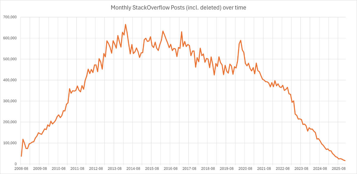
I also think that its AI, especially for new users. I mean AI is good at coding or spotting errors and asking an AI often gets you an answer way faster than starting a forum post. For example here is a chart of stack overflows posts
 2 points
 -
Hello, I'm back here once again to bring up a very interesting topic: How can AutoCAD (installed on a Windows 10 tablet with an integrated GNSS receiver) be made to display its real-time UTM position (or latitude/longitude), for example through a block? Is this possible? Are there any Lisp routines capable of achieving this?1 point
-
I worry that information will become like entertainment. We used to have a few TV channels, they were free, and we trusted their information. Then came cable, which grew into a mess of garbage that came through one provider, so you paid for things you mostly didn't want. Then came streaming, which is turning into a handful of providers with even more garbage, and you pay for each provider. AI may turn out like that: a few providers, with answers of questionable quality, at prices we can't afford. What would make sense to me is to create repositories of knowledge, curated by an AI. As it is, you have to ask similar questions, and the AI starts from scratch every time. Wouldn't it make more sense to treat the AI like someone with institutional knowledge? If you had a repository for AutoLISP code, for instance, all of us could contribute to it and maintain it. You might have to pay for your answer, but you would know it was correct and useful.1 point
-
Are you able to dive into Windows itself a little - been a while since I needed to do anything similar though so this might not be possible. Close everything and set the receiver going, record some data, say 5 mins or something. Windows of old let you search the whole system for every file... might be able to limit that to 'modified in last hour' (or whatever). This might bring up the saved data, might be able to open in notepad and see if it is encrypted / compressed (all the weird characters) or raw data. If is is raw data then you are away and running able to read and modify as you want. Think you would need to show hidden and system files to get the best chance of finding the data. Might work.1 point
-
As an dilettante, I want to say that AI exists only thanks to professionals like you. All the training materials and a lot of codes are written by real people. Therefore, all the applause is for you and only for you!!!1 point
-
Some suggestions. Go back to who you bought the device from, they may have something. If it was say Amazon not sure. Look on the manufacturers web site for more info contact them. Brand, model etc ?1 point
-
In real time? I think is saw one for like $300 will post later tonight. -edit I can't find it was like dtool or something1 point
-
Yeah, my thought would be to use an external app to talk to the receiver, save the coordinates to a text file somewhere continuously - probably by overwriting a simple text file 'X-Coord Y-Coord Z-Coord Description' - same format all the time - all done outside of CAD. Have CAD running and using a delay (https://forums.autodesk.com/t5/visual-lisp-autolisp-and-general/using-delay-command-in-scripts/td-p/5497881 for an example) get CAD to read this file as necessary, plot the point1 point
-
Your trying to talk to an external device, something that Autocad was never really designed to do out of the box.. Other than say a Digitiser. Yes in survey software including CIV3D there are programs that talk to survey instruments, but some one has writen say a .NET interface to do the talking part. So you need a external program Python may do it for you, Lisp is a pretty low level language when it comes to interfaces. You need functions that do that and they are probably not built into the Lisp interpreter. Bricscad has added lisp functions to its software they are not available to say Acad as improvements. In the case of mobile phone photos I used a 3rd part program to read the details from the jpg images so could get the lat and long and insert in a dwg at correct location. Using lisp could call the other external program. look at Startapp can call a bat file. "Need a thread" then why not talk to hand held distance measures, I am sure others would come up with other devices also that they would like plug and play.1 point
-
Hi Daniel (Its_Alive) and everyone in this thread, I have been analyzing this project thoroughly, and the architectural concept behind your SQLiteLsp extension is brilliant. Having a dedicated BRX module with an embedded SQLite engine that exposes clean AutoLISP functions like (DSQL_OPEN), (DSQL_ASSOCQUERY), and (DSQL_CLOSE) is exactly how professional data-driven CAD/CAM applications should be built. However, after running a deep compatibility check for our current enterprise furniture design engine (project ZEN PRACA V2B34), we hit a classic deployment bottleneck. The original module was compiled for BricsCAD V12 around 2011. Even looking at later iterations for IntelliCAD, relying on a pre-compiled binary extension (.brx / .irx) creates a heavy production risk regarding x64 architecture alignment, modern compiler library dependencies, and strict binary compatibility with newer host CAD versions. Because we are currently stabilizing our central parametric engine, we have made a strategic decision not to plug the old V12 BRX module as a production dependency right now. Introducing an external binary at this critical stage could create a second "source of truth" and lead to dependency hell, distracting us from core geometric validation. That being said, the SQLite philosophy is absolutely a GO for our next development phase, but as a clean data persistence layer structured into a strict three-tier architecture: Data Layer (SQLite): To store externalized project profiles, global cabinet variables (PARAMETRY_SZAF), construction tolerances (PROFILE_KORPUSU), zoning maps (MODULE_MAP), internal equipment payloads (shelves, rods, drawers), and manufacturing logs (BUILD_MANIFEST, BOM). SQLite is the perfect serverless, file-based standard for this, especially with the engine being actively developed (up to version 3.53.2 in mid-2026). Logic Layer (Central LISP Engine): Our pure AutoLISP core that reads these parameters, validates manufacturing constraints, and calculates the exact spatial coordinate plans. Presentation Layer (DWG): The clean, visual 3D output generated by a fully controlled and audited geometry builder. Our Roadmap: We are first finalizing the central engine and rule registry using native, structured LISP association lists (which perfectly mimic the flat row-and-column layout of a relational database). Once the geometry is 100% robust, we plan to write a lean, modern SQLite adapter tailored specifically for our V2B34 schema, completely free of legacy binary dependencies. Thank you for this thread—it completely validated our choice to move towards a relational database structure for complex parametric wood-engineering projects! Best regards, Zen1 point
-
Did you have a look at this? SQLite for AutoLisp https://www.theswamp.org/index.php?topic=28286.0 I haven't updated it in a while though1 point
-
Also, this work was the whole reason I made SQLite for Autolisp, to handle the zillions of parameters. Could automatically select the correct drawer hardware, I only had Grass and Blum though, they both sent me all the blocks too so I could use them in sections, I should have saved all that stuff1 point
-
I think you’ll get into trouble with the way your parameters are laid out. Example, the user may not have access to vertical grade laminate, or may wish to use cabinet liner, or just melamine. These thickness changes will have a big impact. You will need parameters for the possible, inside, inside finished, outside, outside finished T_SIDE, the left might have a finished end while the right might not. MAT_OUTSIDE_FINISHED + T_LEFT_SIDE + MAT_OUTSIDE_UNFINISHED Edging is another item, i.e. 0.5mm vs 3mm banding will affect the overall depth1 point
-
I personally do not need any software, as Cabinets etc are not in my usual skill set, but keep working on it. Just a comment the house package that I worked on took 12 months to develop. We worked out from day one had to have an integrated package with every module having links to master defuns. Using common variable names throughout code then others can add to code. In one of your other posts you have hinted that is the way you are approaching the task which is good. If you need to save values in the dwg avoid the USER?? variables. I use Ldata it seems to work well.1 point
-
AI really is helpful but often takes re.ques. Without having been so inspired and learning from y'all, I would have no language to com with. One recent review wow for me is HATCHB.lsp. Without it (JTB) ..I'd Not be able to get a hatch boundary period.1 point
-
What about kitchen cupboards do you have those as well ? Indicative cost ?1 point
-
Wow thank you everyone for the comments, general consensus is AI is still not getting close to 100% solutions or when solving very complex task. Yes part of the answer may be that there is just so much code out there now, so a search finds an existing answer.1 point
-
AI is a mixed bag for me. Copilot can be infuriating at times — it keeps using LISP functions that aren’t supported in AutoLISP, or ACAD‑only functions that don’t work in BCAD. It can wander off into rabbit holes even after you’ve told it not to, and sometimes it changes working code for no reason and breaks it. But with some persistence and back‑and‑forth, it can produce really good functions. I’ve also tried Claude, which is much better in lots of ways — the code tends to run first time. If i run out of credits then I continue on with co-pilot. I used Fable just before it was banned, and that was pretty amazing too. AI still needs a lot of guidance to produce anything worthwhile. It can be overconfident, sometimes it doesn’t listen and it doesn’t always think clearly about the end goal. I’m currently updating a lot of routines I’ve cobbled together over the years, and AI is helping polish them and fix issues I’d hit a wall with. It’s here now, and it’s not going anywhere. Can forums embrace it? I’m not sure. With the amount of knowledge stored on these pages, maybe CADTutor could even build its own AI. No idea how easy or expensive that would be, mind you...1 point
-
For Al, I always assume it is nothing more than google on a few steroids, not a lot more. For LISPs - like google, if you ask it for snippets where you are stuck it will get something that works, but something more complex not really. Then you have to break it down get the snippets and sew them together. Anything new or novel that isn't out there is won't cope. So for my work it might help with a few LISPs to improve accuracy or efficiency but the actually money maker and drawing stuff, not seen anything close yet. Made me think though, SLW210, have we actually worked out all (or nearly all) the LISPs we need and just need to find them? (apart from the very specific ones). Last comment - RLX, very true, if I pass anything around the company I need to be able to maintain it, an undocumented 'black box' solution still needs time to make it work.1 point
-
To be fair Soildworks Forum layout/search is trash. I have never started from the forums to find something its usually a link from a search engine to there. The search engines like google are in a fight right now with AI chatbots and in the end content creators/websites are being affected. going to get worse before it gets better. I genially like AI but its a tool not a solution. but most people unfortunately are ok with "good enough". AI companies are claiming 100x efficiency that is impossible. I liken it to a side scroller game like the dino chrome 404. play that 100x speed and see how far you get.1 point
-
Posts are one thing, but what about the actual traffic? Like I stated, most fora already have the answers to questions, so often no need to interact and make a post. CADTutor shows most online 9,928 April 2nd 2026, which was probably a lot of AI bots, etc.1 point