Search the Community
Showing results for tags 'simulation'.
Found 11 results
-

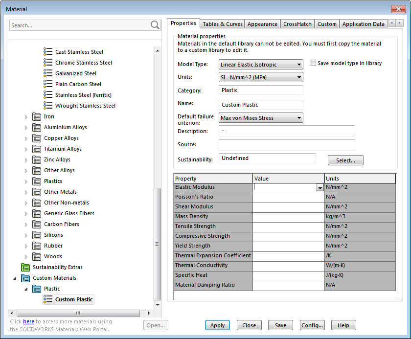
flow simulation How to convert ABS-M30 material properties from pdf to required parameters from image?
Aleksandar posted a topic in SolidWorks
Hello. How to convert the data from the pdf to the appropriate data required here: (as image) Need for simulation in Solidworks. Thanks. ABS-M30.pdf
-
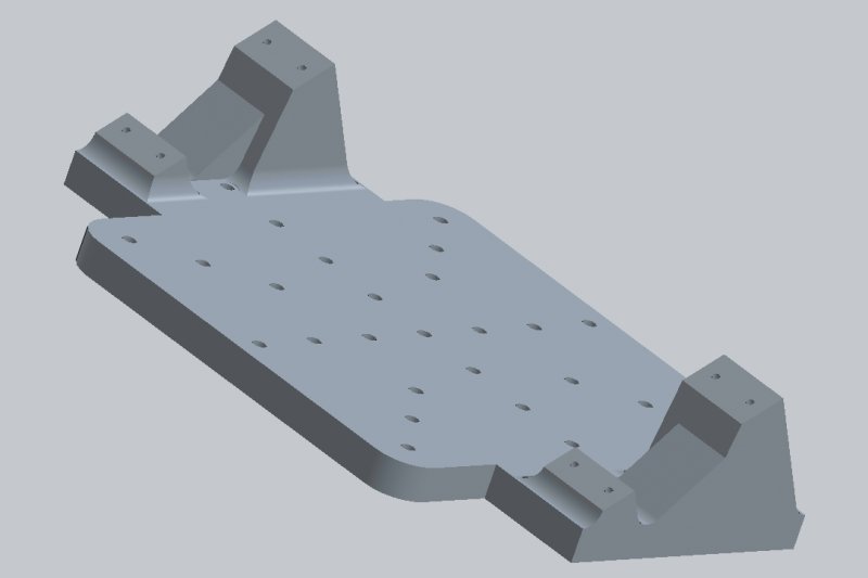
I am attempting to run a simulation that consists of the following: a heat exchanger mounted to a vibration test fixture, which is mounted by bolts to a flat vibration test stand. I applied fixed geometry to the bolt holes, and a mass load to where the heat exchanger is to be mounted. When I run the simulation, I get low resonant frequencies. I believe this is because the areas with the tower pieces are displacing a large amount. I would think that adding a roller would model the effects of the flat test stand which the fixture is mounted to, as it would be preventing the fixture deflecting downwards, but the roller in solidworks prevents upwards deflection as well. I am wondering if anyone has an idea to constrain the fixture to prevent downwards deflection on the bottom of the fixture, without preventing upwards deflection.
-
I have a question about SolidWorks Stress Analysis. How do I incorporate the grain of the wood with the stress simulation. Because the grain of the wood plays a huge role in how much weight a balsa bridge can hold. So I guess my question is; Does SolidWorks allow you to specify the grain of the wood and if so, How do I do it?
-
I'm a mech engineering student and I have no experience whatsoever using any CAD. For a project I'm doing, I want to produce (or even better, have someone do it for me!) a 3D CAD model for a bicycle frame, and then test it against industry standards for fatigue life. I need to some guidance on what the best way to go about this is. I gather Inventor can be used to produce the model, although I have downloaded and started playing with Inventor Pro 2013 Student Edition, and it's intimidating to say the least. Getting to grips with it and trying to produce a model is going to take a very very long time. I don't want to invest this time if A) there is a better route B) I can find someone to do it for me The project is not about my personal ability to produce models, and this part of it is only going to be a time-sink/distraction from my actual aims. Furthermore I gather that Inventor cannot do fatigue-life analysis, but Autodesk Simulation does? I'm thinking that perhaps I can use the stress outputs from Inventor's FEA modelling to then hand calculate fatigue life - it would probably be quicker than spending days and days struggling with yet another package I don't know how to use. Is this feasible? I'm pretty much all at sea with this (computer) stuff, I haven't been taught it practically, and any suggestions on how to proceed are gratefully received (even if those suggestions are 'Use this other package which is simpler and quicker to get up and running on').
-
Let’s face it – working with composite materials is hard that's why Autodesk Labs has released project Cassidy, a free technology preview that allows users to simulate bending loads on 3D models of composite plates. The standalone application for Windows imports your CAD file and walks you through the process of applying bending loads to the geometry. We want your feedback! Help us drive the future of this technology by trying it out today. If nothing else, use it to say you have designed a part with composite materials... Learn more and download this free technology preview here: www.autodesk.com/cassidy
-

Updating Property in Objects Definition in XREF DWGs
zetazee posted a topic in .NET, ObjectARX & VBA
Hi, I am developing an simulation application, leveraging on using Space objects and applied additional Property Set Definitions for Space objects where I introduced a new Property "Value". I applied a display theme to my DWG, and based on the value of the Property, different colours wil be displayed according to the display theme. For a single DWG file containing the building, I am able to simulate the colour changes by updating the “Value” Property in the Spaces using .NET APIs functions such as PropertySet.SetAt, and commiting the transasction. However, one building can consist of many different levels, and I have split up the modeling of the building into its separate levels. For example, a 3 storey building, I will have 3 DWG files for each individual levels. A main empty DWG was then used to XREF the 3 levels, to combine the different levels into a whole building. I would like to simulate such colour change through the main DWG which references my individual level DWGs. Any idea what .NET API I can use to access the XREF DWGs in my main DWG, so that I can update the "Value" property in all my Space objects? -
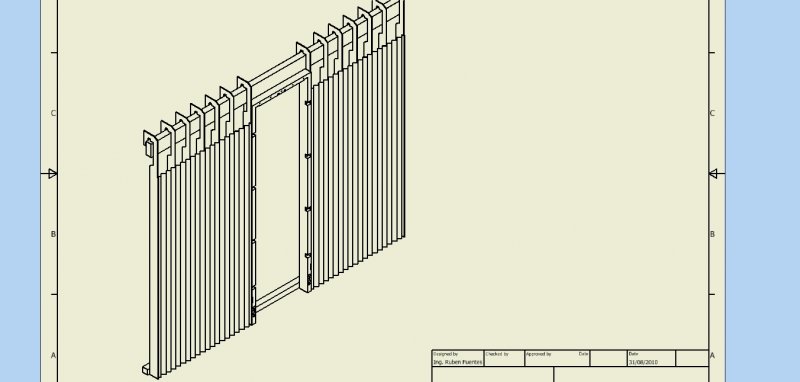
Hi everybody. I need to make something like an accordion, i have attached the picture what i am talking about, the really problem is that it is not flexible, i can not move it because the the fold can not adapt to the movement when i want to simulate it. I just can resolve the problem of design using sheet metal part and make a contour flange. Is any way to make it possible ans simulate it like real life?