Search the Community
Showing results for tags 'weight'.
Found 6 results
-
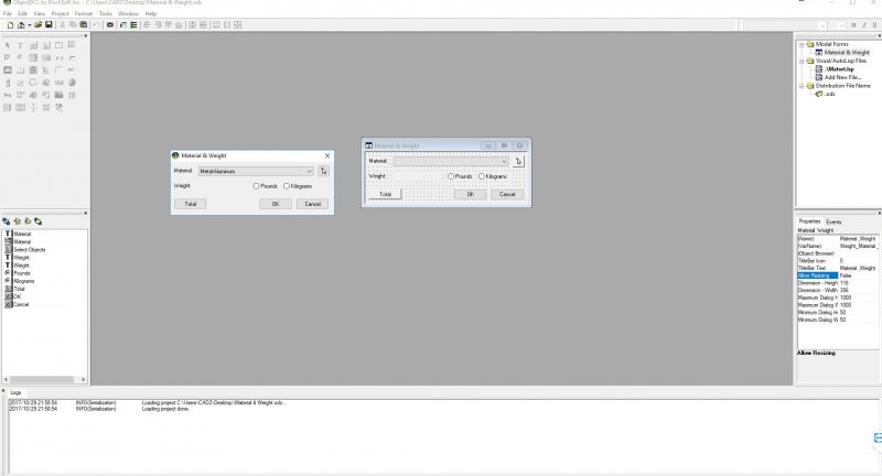
Hello everyone, I’ve dove head first into the overwhelming world of Autolisp… and needless to say I’m in way over my head. I’ve been trying to put together a program for AutoCAD 14 with a dialog box that will allow the user to pick from a drop down list of standard materials/click a “select objects” button… apply selected material to 3D solids and have it display the weight based on the volume of the solid/s. Furthermore, I have added two radio buttons: one for imperial measurement and one for metric measurement. There is also another “select objects” Total button to calculate and display the combined weight of the entire 3D solid assembly. I used a program called ObjectDCL to design the dialog box (ODC file and image attached). But that’s really as far as I got. I found these links as a starting point but couldn’t figure out how to tie it all together: http://www.ellenfinkelstein.com/acadblog/create-a-custom-function-in-autocads-calculator/ http://cadtips.cadalyst.com/mass-properties/tip-2258-calculate-weight http://cadtips.cadalyst.com/mass-properties/tip-2258-calculate-weight http://www.cadtutor.net/forum/showthread.php?50384-Calculating-weight-of-2d-shape-amp-3dsolid-object-by-asigned-material&highlight=material+density http://www.cadtutor.net/forum/showthread.php?89753-Help-please-need-to-combine-to-lisp&highlight=material+density I have the list of materials ready to insert along with the densities in lbs/in^3 I’m hoping one of you programming geniuses could please put it together to get it working as it is intended. I’m also hoping that I could then study that code and get some clue as to how it all works. I'm intrigued by the potential of this programming language and would love to be introduced to it by one of the many experts on this forum. Thanks in advance and please let me know if I missed anything. Matwt.lsp ODC.zip

-
I have thousands of sketches in autocad and need to calculate the weight for each sketch. The sketches are all in 2D format. The sketches are of shafts with different diameters and lengths. Each shaft has a major diameter and then a varying number of steps each with its own diameter and length. The dimensions of most of the sketches are associated to objects in the sketch; however, there are some sketches with non-associative dimensions. Is it possible to write an AutoLisp program to go through all of these sketches and pull the diameter & length of each shaft (including each diameter and length of each journal step) and then use the information to calculate volume and weight. Currently, I have an excel program that will calculate the weight if I type in all the length and diameter dimensions of the objects. The task is repetitive and time consuming. Writing a program may help expedite the task. Any advice would be helpful. Thanks
-

Edit line weight in nested blocks of all XREF drawings.
crsimmons posted a topic in AutoCAD Drawing Management & Output
The 2D drawings I am working with were exported from 3D REVIT files to 2D AutoCAD files. There are several XREFed drawings that are both mechanical and architectural from the original REVIT files that for whatever reason, the block's line weights came over with line weights of 70 in those blocks. When I plot, the objects are a blur with the line weight so high. I tried using the command "setbylayer" but that didn't work since nested blocks still had lineweights of 70. Is there a VBA or LISP routine to run through all the blocks (including nested) that can change the line weights to a given number? Thank you for any advise/recommendations. -

Get Line Weight in Layout? Printing OK
D1-Xen posted a topic in AutoCAD 2D Drafting, Object Properties & Interface
I am aware some users like their lines very sharp and neat in the layout and make the line weight appear in the printing process. However, I am wondering if I can see the the lines weight applied while drawing in AutoCAD. Is just I believe it will give a better "print preview" as I am working. It will be very annoying to keep going back to print layout to "hummm... How does the line look?" PS: Yes, I know how to change the line weight. -
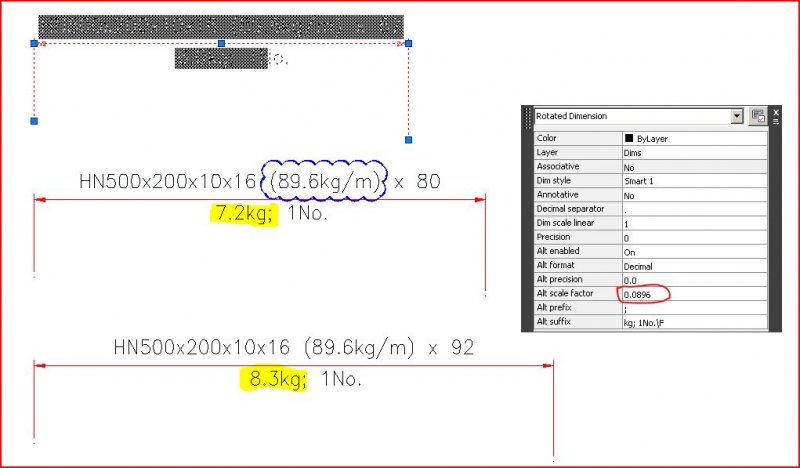
When I am doing fabrication drawings, I resent time spent on the calculator determining profile weights. I use the calculation field in the alternate scale factor to generate item weights. I know that the FINISHED weight of an item is most quickly calculated using the MASSPROP feature, but as it subtracts volume which has been drilled, radiused, chamfered or whatever, I do not use that, as it shorts the fabricator for steel which was removed during fabrication. I typically use metric dimensions with units mm. I use my quick properties palette, and have customized it so that it displays ALTERNATE ENABLED & ALTERNATE SCALE FACTOR. After dimensioning a profiled section (with a known kg/m value) I enable the alternate dimension in my quick properties palette and change the alternate scale factor, replacing it with the kg/m section weight and moving the decimal point to the left 3 decimal places (yielding the kg/mm profile weight). In this way, the alternate dimension feature displays the weight of the section length below the dimension. Particularly useful if you have multiple items from the same profile section. Usually I do not want that information to display on the dim line of the issued drawing, so after noting it on the drawing, I disable the alternate enabled option on the quick properties palette returning the dimension to my default publishable dimstyle. This trick is only as useful as one's resolve to ensure that the CORRECT kg/mm profile weight has been entered into the ALTERNATE SCALE FACTOR, and that the DIM SCALE LINEAR is appropriately set. All too often automatic functions breed inattention and laziness. Keep your eyes on the ball. As is generally the case, garbage in, garbage out. :wink:
-
 Hello out there, In my 2D drawings I use a lot of splines. I restore/convert antique drawings of ancient boats and sailplanes in/to Autocad 2012. I use these drawings as a raster image and draw precisely over the handcrafted lines. So these original drawings contain a lot of hand shaped (organic) formes that go through, by dimension defined, fitpoints (so as indicated on the original plan) and are tangent to other lines elsewhere in the plan. As I draw a lot of these splines, I want to manipulate the default settings in order to save time and effort. Is there a way in Autocad 2012 to increase the weight, by default, of a vertex point in such a way so that the vertex point becomes a fit point by itself? What is the maximum value to give to a vertex point? Does it become a fit point then? When a fitpoint and a vertex point coincide, how to keep them stay that way; that means relocate both at the same time when editing the spline, and not one seperately. Are splines the 'necessary evil' in this case or is functional alternative advise available? I don't want to see these splines to leave the points they absolutely should go through as I clicked them when drawing the spline. I want splines to be smooth, and to stay smooth even after replacing fit points or vertici. And I don't have the time to re-re-re-re-refine every single spline I draw, as I draw so many. I've tried so hard to fix this problem, but I can't, probably because of incompetence. Sorry. Rainy greetings from Flander's fields anyway, and thanks in advance for the shared intelligence, Kouros Van Karibou.