All Activity
- Past hour
-

Civil Drafting with AutoCAD Project-Civil Drafting with AutoCAD Project
nelsonm replied to nelsonm's topic in Student Project Questions
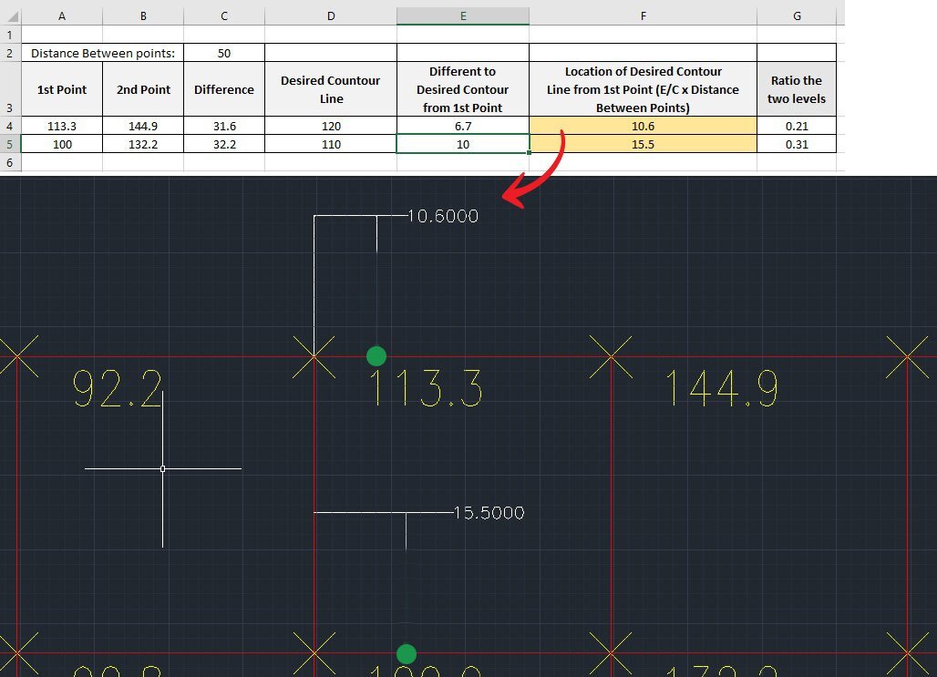
Thank you very much for the guidance. I already know your instructions, and this is what I did. Could you tell me if this is correct?
- Today
-
If I understood the request correctly... This could be a design start, it uses the oblique block of the dimension. (vl-load-com) (defun circle2lw (e / dxf_ent pt_cen radius fst_pt opp_pt) (setq dxf_ent (entget e) pt_cen (cdr (assoc 10 dxf_ent)) radius (cdr (assoc 40 dxf_ent)) fst_pt (polar pt_cen 0.0 radius) opp_pt (polar pt_cen pi radius) ) (entmake (list '(0 . "LWPOLYLINE") '(100 . "AcDbEntity") (assoc 67 dxf_ent) (assoc 410 dxf_ent) (assoc 8 dxf_ent) (if (assoc 6 dxf_ent) (assoc 6 dxf_ent) '(6 . "BYLAYER")) (if (assoc 62 dxf_ent) (assoc 62 dxf_ent) '(62 . 256)) (if (assoc 370 dxf_ent) (assoc 370 dxf_ent) '(370 . -3)) (if (assoc 48 dxf_ent) (assoc 48 dxf_ent) '(48 . 1.0)) '(100 . "AcDbPolyline") '(90 . 2) '(70 . 1) (cons 43 0.0) (cons 38 (caddr fst_pt)) (if (assoc 39 dxf_ent) (assoc 39 dxf_ent) '(39 . 0.0)) (cons 10 (list (car fst_pt) (cadr fst_pt))) '(40 . 0.0) '(41 . 0.0) '(42 . 1.0) (cons 10 (list (car opp_pt) (cadr opp_pt))) '(40 . 0.0) '(41 . 0.0) '(42 . 1.0) (assoc 210 dxf_ent) ) ) (entdel e) (entlast) ) (defun c:Mybreak ( / ent obj_brk pt_brk vlaobj pr deriv alpha) (setvar "DIMBLK" "oblique") (while (setq ent (entsel "\nBreak point: ")) (setq obj_brk (car ent)) (cond ((member (cdr (assoc 0 (entget obj_brk))) '("POLYLINE" "LWPOLYLINE" "LINE" "ARC" "CIRCLE" "ELLIPSE" "SPLINE" "XLINE" "RAY")) (setq pt_brk (cadr ent)) (if (eq (cdr (assoc 0 (entget obj_brk))) "CIRCLE") (setq obj_brk (circle2lw obj_brk))) (setq vlaobj (vlax-ename->vla-object obj_brk)) (initget 1) (setq pt_brk (vlax-curve-getClosestPointTo vlaobj (trans pt_brk 1 0) nil ) pr (vlax-curve-GetParamAtPoint vlaobj pt_brk) deriv (vlax-curve-getFirstDeriv vlaobj pr) alpha (atan (cadr deriv) (car deriv)) ) (command "_.break" obj_brk "_none" pt_brk "_none" pt_brk) (initget 1) (command "_.-insert" "_oblique" "_scale" (distance (trans pt_brk 0 1) (getpoint (trans pt_brk 0 1))) (trans pt_brk 0 1) (angtos alpha (getvar "AUNITS") 13)) ) (T (princ "\nThis object can't be break!")) ) ) (princ) )
-

copy viewport and content...is it possible?
SLW210 replied to leonucadom's topic in AutoLISP, Visual LISP & DCL
You might try Lee Mac's Steal from Drawing | AutoCAD | Autodesk App Store. I just do a SAVE or SAVEAS on the drawing and make a new exact COPY of the drawing. If I have similar drawing that could use the other viewport and settings, I just drag the Layout from one drawing to the other with Design Center. There is an Export Layout to Model... when you right-click a Layout TAB and before that option was in AutoCAD there were some programs that would do that. To do what you want looks to be a lot of work for a LISP. -
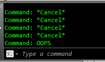
You need to use ERASE to remove items in order for OOPS to actually restore it.
-

Beug Autocad dans la fenêtre de présentation
Pepsifoldu69 posted a topic in AutoCAD Bugs, Error Messages & Quirks
Bonjour, Mon équipe et moi effectuons des exports autocad sur un fichier comportant beaucoup de Xref. Nous avons tous le même matériel informatique. Un des membre de notre équipe n'a aucun soucis, nous avons comparé certains de nos paramètres, il nous semble que nous ayons les mêmes (mais peut-être n'avons nous pas tout étudié). Le beug ne se déroule pas dans l'espace objet qui fonctionne - nous pouvons nous déplacer dedans- mais lorsque nous cliquons sur l'une des présentations, la fenêtre se fige à jamais et il est donc impossible de réaliser les exports. Ceci est embêtant car actuellement un seul ordinateur de notre équipe est en capacité d'effectuer les exports. Nous sommes tous sur la même version autocad : Autocad LT2026. Merci pour votre aide, Cordialement. -
Pepsifoldu69 joined the community
-

command breakline from lsp...
Emmanuel Delay replied to leonucadom's topic in AutoLISP, Visual LISP & DCL
Command CBL: puts the Breakline symbol 4.0 units from the start, the breakline symbol is 1.0 units wide, and the tip is 0.4 units up or down the line. Obviously feel free to change those values. command CBLU: Same, except the user must give all the values. ;; Custom Breakline ;; @params ;; ps: start point ;; pe: end point ;; gap: gap between the two halves of the lines ;; loc: location of the center of the gap ;; tip: vertical size of the tip of the breakline symbol (default there's is 70° angle, but we'll give tip size) (defun CustomBreakLine ( ps pe gap loc tip / angl dst pline pl pd pm pu pr ) (setq angl (angle ps pe)) ;; angle (setq dst (distance ps pe)) ;; distalce of the line (without the breakline symbol) (setq pm (polar ps angl loc)) ;; mid point of the gap (setq pl (polar ps angl (- loc (/ gap 2.0)))) ;; left point of the breakline symbol (setq pr (polar ps angl (+ loc (/ gap 2.0)))) ;; right point of the breakline symbol ;; down tip of the breakline symbol (setq pd1 (polar pl angl (/ gap 4.0))) (setq pd (polar pd1 (- angl (d2r 90.0) ) tip)) ;; up tip of the breakline symbol (setq pu1 (polar pm angl (/ gap 4.0))) (setq pu (polar pu1 (+ angl (d2r 90.0) ) tip)) (setq pl (drawLWPoly (list ps pl pd pu pr pe) 0)) ) ;; degree to rad (defun d2r (d / ) (/ (* pi d) 180.0) ) ;; Returns the middle of two points (defun mid-pt (p1 p2) (polar p1 (angle p1 p2) (/ (distance p1 p2) 2.) ) ) ;; makes a polyline object with entmakex (defun drawLWPoly (lst cls) (entmakex (append (list (cons 0 "LWPOLYLINE") (cons 100 "AcDbEntity") (cons 100 "AcDbPolyline") (cons 90 (length lst)) (cons 70 cls)) (mapcar (function (lambda (p) (cons 10 p))) lst))) ) ;;;;;;;;;;; ;; Custom BreakLine, User input values (defun c:cblu ( / ps pe gap loc tip ) (CustomBreakLine (setq ps (getpoint "\nStart pont: ")) (setq pe (getpoint ps "\nEnd pont: ")) (setq gap (getdist "\nGap distance: ")) (setq loc (getdist "\nLocation of the gap center (enter value, or select two points: start point + point of the gap): ")) (setq tip (getdist "\nTip height: ")) ) (princ) ) ;; Custom BreakLine, preset values (defun c:cbl ( / ps pe gap loc tip ) (CustomBreakLine (setq ps (getpoint "\nStart pont: ")) (setq pe (getpoint ps "\nEnd pont: ")) (setq gap 1.0) (setq loc 4.0) (setq tip 0.4) ) (princ) ) (princ "\nCommand CBL for Custom BreakLine: ") (princ) Happy with this? -
That's because you need to do something before issuing the oops command. I think there is a thread here differentiating oops and undo command.
-

Dynamic Blocks corrupted after a while of usage in ZWCAD
cad_tutee replied to cad_tutee's topic in AutoCAD Drawing Management & Output
I did think of using lisp, but i am not too familiar with it and it may get complicated if i needed the data within the text to get sorted in excel. Hence, the blocks. I data extract all the attributes of the blocks and their layer names, which end up in their respective columns in Excel. -
 Claudio Sousa joined the community
 - Yesterday
-
master LEE I tried the command, but nothing appeared on the command line, so I doubted I could do it.
-
You created this thread before even trying it in your AutoCAD?
-

copy viewport and content...is it possible?
BIGAL replied to leonucadom's topic in AutoLISP, Visual LISP & DCL
Did you google found lots of ideas. -
hello : I'm wondering if this command can be used from lsp, as I'd like to interact with it. for example by giving the default size and position of the break symbol Any information you have is welcome. thanks
-
Top 20 AutoCAD Customizations – Part One: Tuesday Tips With Frank
BIGAL replied to The AutoCAD Blog's topic in AutoCAD Blogs
Re item 9, I used CIV3D so rather than swapping workspaces made a pop menu with a few of the CIV3D commands that we used often. The menu was saved into the drafting workspace. If you can use notepad you can make a new menu. Just open the CUI and copy the relevant commands to your notepad. If want more details just ask. Just a PS every user had their own workspace saved as their name, to avoid any corruption of the default workspaces. -
Dynamic Blocks corrupted after a while of usage in ZWCAD
BIGAL replied to cad_tutee's topic in AutoCAD Drawing Management & Output
For me I generally write a custom data extract using lisp. That can include mleaders with text or a block with attributes have you thought about going that way ? What object and properties are you extracting and where does it end up Excel etc. -

copy viewport and content...is it possible?
leonucadom posted a topic in AutoLISP, Visual LISP & DCL
hello: I'm still wondering if this is possible, selecting a viewport in paperspace and that the content of the selected viewport is selected and all of this is saved to the clipboard and then you can copy it to another dwg in a single move. anyone who knows something about this thanks -
THANK YOU SO MUCH, I DIDN'T KNOW I HAD IT
-
In this link, it's written that OOPS command exist : In AutoCAD since version ≤ R12...
-
hello: I've heard about the command OOPS Unfortunately, the AutoCAD I use at work is version 2013 Does anyone know if there is an LSP routine command for that? IT WOULD BE GREAT TO INCORPORATE IT Any advice is welcome. thanks
-

Top 20 AutoCAD Customizations – Part One: Tuesday Tips With Frank
The AutoCAD Blog posted a topic in AutoCAD Blogs
There are times when I discuss customizing AutoCAD, and I often receive a response similar to: “Oh, but I’m not a programmer.” No, no, no, you don’t have to be a programmer to set up AutoCAD to fit your workflow better, or in some cases, improve it. With that said, I present to you my list of top AutoCAD customizations for non-programmers. In this two-part series, the first 10 are included today. In no particular order, let’s kick it off. 1. Quick Access Toolbar Keep your most frequently used tools in the Quick Access Toolbar (QAT) at the top of your screen. Customize the QAT by clicking the small, pull-down control button on the right. You can check and un-check the commands you want quick access to. For a fast way to add a Ribbon command to the QAT, right-click any command icon on the Ribbon, and then select Add to Quick Access Toolbar from the pop-up menu. Similarly, right-click on any Quick Access Toolbar item to remove it. 2. Clean Screen Need to max out your screen space? CTRL-0 is your friend. The Ribbon and Palettes will be hidden, and AutoCAD will maximize to fill the entire screen. The QAT will remain on, so make note of the previous tip. CTRL-0 again to toggle it back. Of course, you can use the icon on the status bar as well. 3. Anchor Palettes AutoCAD’s many palettes are wonderful productivity enhancers, but not so great when they get in your way. Keep your favorites available with a simple mouse rollover by anchoring some left and some right. They take up almost no space when anchored, so you can still access their functionality while keeping your drawing editor clean and visible. 4. Right-Click Delay Do you still use your mouse right-click as Enter? If you’re not using the contextual pop-up menus when you right-click, you’re missing out on one of my favorite productivity enhancements. If you just can’t give it up, you can still have the best of both worlds by utilizing the time-sensitive right-click feature. You’ll find its control in the Options dialog, and when enabled, right-click will still function as you prefer, but now, by holding down the mouse button just a little longer, you’ll get the contextual pop-up menu instead. 5. Command Alias An AutoCAD command alias is a shortened name or abbreviation of a command name. Don’t like a default alias name? Change it! It’s easy. For example, a lot of people prefer C to be Copy instead of Circle. Does one of your often-used commands not have an alias? Add it yourself. Aliases live in a file called acad.pgp. And here’s the thing – it’s your .pgp file, not anyone else’s, so you can define them as you please. I’m a firm believer that using aliases and keyboard shortcuts, in conjunction with not taking your eyes off your work, is the best way to increase your speed and efficiency. Personally, I like to keep my most-used aliases mapped to the left side of the keyboard. That way, I don’t have to take my hand off the mouse or my eyes off my work to find a letter on the right side of the keyboard. 6. Places Stop wasting time by continually navigating multiple levels of folders in the File Open dialog box. Once you get to your folder, add it as a new entry in the Places pane of the Open dialog. Click on “Tools” in the upper-right corner, then select “Add Current Folder to Places.” A new icon will appear with the name of the folder. Now you can click on your new Place to jump right to that folder. If you find that you have multiple icons with the same name – “CAD,” for instance – just right-click on the icon, select Properties, and change the name to something that makes more sense, such as the project name. 7. Ribbon States The Ribbon doesn’t have to take up so much real estate. You can minimize it down to either panel buttons, panel tabs, or just titles. Decreasing the Ribbon’s footprint doesn’t affect its functionality, and it may just improve yours. 8. Floating Editor Have you ever had to work on one drawing while referencing another? You might want to take advantage of pulling your file tab off of the application, and to another location (such as another monitor). Don’t worry about losing any functionality either. The floating window has its own Command Line, and you can still use the Ribbon and Quick Access Toolbar from the main application while in your active floating window. When you’re done, use the title bar to drag it back to the file tabs area, or if you prefer, you can right-click the title bar, where you’ll find commands to either move it back. 9. Multiple Workspaces Do you work in multiple ways in AutoCAD? One day, you’re doing schematic drawings, such as wiring diagrams, and the next, you’re laying out 3D piping. Set up a separate workspace for your various workflows, containing the tools and palettes you need for the job. 10. Command Line Options AutoCAD’s Command Line is no longer just a utilitarian device to input commands. Now, it’s a multi-functional digital assistant that you can customize to match your preferences. Click on the wrench icon, and you can find tools to change your input settings, prompt history, and search options. It’s all just a wrench-click away! What’s Next? Stay tuned for the next installment to learn more AutoCAD customizations! More Tuesday Tips Check out our whole Tuesday Tips series for ideas on how to make AutoCAD work for you. The post Top 20 AutoCAD Customizations – Part One: Tuesday Tips With Frank appeared first on AutoCAD Blog. View the full article -

Civil Drafting with AutoCAD Project-Civil Drafting with AutoCAD Project
ReMark replied to nelsonm's topic in Student Project Questions
Your points will fall on the grid lines not inside the boxes created by the grid lines. -
Dynamic Blocks corrupted after a while of usage in ZWCAD
cad_tutee posted a topic in AutoCAD Drawing Management & Output
For context, I am using ZWCAD 2024 currently and I've created a dynamic block to be used in ZWCAD as an alternative to Multi-leaders to be an easier method to be able to DATAEXTRACT because my ZWCAD does not allow data extraction of MTEXT and MLEADERS unlike AutoCAD. I'd made the Dynamic Block to work exactly like a multileader would using, along with other parameters, Multiple Lookup Tables for rotating, extending and flipping the leader without affecting the order of text. That means they had to be created in licensed AutoCAD because ZWCAD's counterpart Flexiblocks do not have the LookUp parameter yet. The blocks worked normally as intended for a while on regular usage(working on, closing and reopening the file multiple times), but they stopped behaving like a dynamic block altogether suddenly after a few days on reopening the file. The blocks now seem to have been assigned different names by the software (*U15, *U16, and so) from its original name(m-Drawing M-Leader Block). I have attached the files below: Issue.dwg - File with the problematic Dynamic Blocks MultileaderDynamicBlock.dwg - File with the original Dynamic Block I have noticed this behavior with some other dynamic blocks in the files that I receive from consultants once in a while. Is this because of using dynamic blocks created in AutoCAD in ZWCAD? If yeah, why do they work perfectly for a while only to stop working all of a sudden? Is there a way to reverse this? I'd tried to replace the corrupted blocks with the original dynamic block reference, which would have itself been sort of a tedious task as there were so many instances in the drawing, but ZWCAD no longer recognizes the corrupted blocks as "blocks". ChatGPT and other LLMs are of limited help, so please help a brother understand and, if possible maybe, correct this issue. Or is there an alternative to this? Cheers! Issue.dwg MulltileaderDynamicBlock.dwg -
cad_tutee joined the community
-
 Zar joined the community
 - Last week
-
Oh that's cool, thanks for that lrm that will save quite a few steps in my process! Thanks again
-
Bit odd yes tested in Bricscad, I will look at the getcellextents, this gives the XY position of the corners of the table cell. If the line is 69 times repeated it sounds like that is the problem. I will make a little test program so can look at what is going on when calculating the Pt1 and Pt2. the code is done that way so if row height is changed for other users the lines are still central in the cell. Add the (princ line and look at the Y value displayed, it should change for every row. Please let me know if it is not changing. (setq pt2 (list (nth 6 pts)(nth 7 pts) 0.0)) (princ (strcat "\n" (rtos (cadr pt1) 2 3) " ")) (setq vdist (/ (- (cadr pt1) (cadr pt2)) 2.0)) Another test could some one try on Acad. 0 is 1st column. (setq objtable (vlax-ename->vla-object (car (entsel "\nPick a table ")))) ; put a number like 3+ in row variable ; then copy this line to command line change the 3 etc to 4 5 6 and so on ; The Y value should change (setq pts (vlax-safearray->list (vlax-variant-value (VLA-GETCELLEXTENTS objtable 3 0 :vlax-false))))
-
Works with BricsCAD. I know you have to wrap points in AutoCAD sometimes with (vlax-3d-point pt2) not sure about entmake tho.
-
 annegrpan31 joined the community
 -
 BHUTUU joined the community
 -

Bolted Connections and Bracings SolidWorks Structure System
mhupp replied to gabriele_biag's topic in SolidWorks
I don't work with this feature alot so might not be the best to answer this. the double L is two single L's just one is rotated. https://www.youtube.com/watch?v=57wTY5b8qcc&t=635s