Search the Community
Showing results for tags 'dynamic block'.
-

Dynamic Blocks corrupted after a while of usage in ZWCAD
cad_tutee posted a topic in AutoCAD Drawing Management & Output
For context, I am using ZWCAD 2024 currently and I've created a dynamic block to be used in ZWCAD as an alternative to Multi-leaders to be an easier method to be able to DATAEXTRACT because my ZWCAD does not allow data extraction of MTEXT and MLEADERS unlike AutoCAD. I'd made the Dynamic Block to work exactly like a multileader would using, along with other parameters, Multiple Lookup Tables for rotating, extending and flipping the leader without affecting the order of text. That means they had to be created in licensed AutoCAD because ZWCAD's counterpart Flexiblocks do not have the LookUp parameter yet. The blocks worked normally as intended for a while on regular usage(working on, closing and reopening the file multiple times), but they stopped behaving like a dynamic block altogether suddenly after a few days on reopening the file. The blocks now seem to have been assigned different names by the software (*U15, *U16, and so) from its original name(m-Drawing M-Leader Block). I have attached the files below: Issue.dwg - File with the problematic Dynamic Blocks MultileaderDynamicBlock.dwg - File with the original Dynamic Block I have noticed this behavior with some other dynamic blocks in the files that I receive from consultants once in a while. Is this because of using dynamic blocks created in AutoCAD in ZWCAD? If yeah, why do they work perfectly for a while only to stop working all of a sudden? Is there a way to reverse this? I'd tried to replace the corrupted blocks with the original dynamic block reference, which would have itself been sort of a tedious task as there were so many instances in the drawing, but ZWCAD no longer recognizes the corrupted blocks as "blocks". ChatGPT and other LLMs are of limited help, so please help a brother understand and, if possible maybe, correct this issue. Or is there an alternative to this? Cheers! Issue.dwg MulltileaderDynamicBlock.dwg -

Choose which attributes to display in Block Reference.
fromMlm posted a topic in AutoCAD Drawing Management & Output
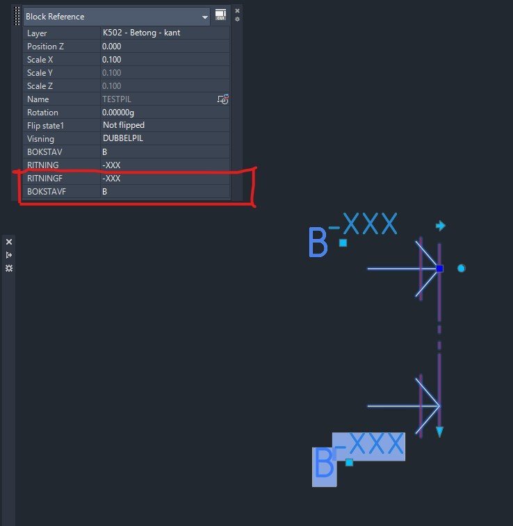
Hi I have two attributes as fields which i dont want to show/display in the Block Reference window. See screenshot. How do I make them disapear there so you dont accidentally change them? Kindly regards Section marker.dwg
-

Dynamic Block - Same Values in Each State?
ILoveMadoka posted a topic in AutoCAD Drawing Management & Output
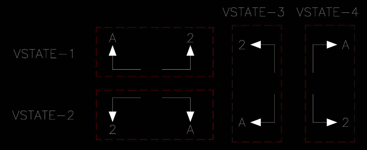
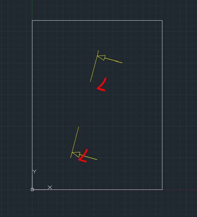
I want to create a dynamic block with 4 visual states. I want two text values to appear in each state but in different places in each state. If I understand correctly you cannot move an attribute from state to state. Fields would work but I have no way of knowing how many of these blocks may be needed in a particular drawing. If I copy the attributes from VS to VS when creating the block, they only are available in the first state. The other states report there is no editable attributes but if I edit the state they are there. Here is a diagram of the 4 visual states. (the red is not part of the block, just a separator) I had created a block with 8 attributes but users found it confusing or difficult to navigate. Is there a way to achieve this in a simpler/better fashion?
-
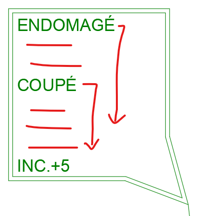
The current routine works but requires 2 major changes (1) and (2). So... basically what I would like to accomplish would be: 1) find a way so that the filtering process accounts for a specific block throughout the drawing instead of :L , but no success on this regard: (if (setq s (ssget "_X" '((0 . "INSERT") (66 . 1) (2 . "`*U*,POTEAUX_PLAN_BLK1")))) (repeat (setq i (sslength s)) (setq o (vlax-ename->vla-object (setq ent (ssname s (setq i (1- i)))))) (if (and (vlax-property-available-p o 'effectivename) (= "poteaux_plan_blk1" (strcase (vla-get-effectivename o) t)) ) (progn ... It works as is, but cannot find a way to incorporate (2 . "`*U*,POTEAUX_PLAN_BLK1") for the dynamic block "POTEAUX_PLAN_BLK1". So I ended up selecting the blocks one by one as an alternative. 2) The attributes on the block are arranged in the same manner as displayed on the tags list. Is it possible to move tags downward by say 2.5 units to re-arrange the position after tags are removed (Photo before & after)? (defun c:foo (/ s tags) ;; List of tags to target (setq tags '( "ENDOMAGÉ" "FISSURÉ" "BANDEJAUNE" "COUPÉ" "TRANSFERT" "<1M" "<3M" "INC.+5" ) ) ;; Select attributed blocks (if (setq s (ssget ":L" '((0 . "INSERT") (66 . 1)))) (foreach e (vl-remove-if 'listp (mapcar 'cadr (ssnamex s))) ; Loop through selected entities (foreach tag tags (if (vl-catch-all-error-p (vl-catch-all-apply (function (lambda () ;; Get the current value of the attribute (cond ;; Case 1: Empty or "NON" -> Set value to "" ((or (eq "" (getpropertyvalue e tag)) (eq "NON" (strcase (getpropertyvalue e tag)))) (setpropertyvalue e tag "")) ;; Case 2: "OUI" -> Set value to the tag name ((eq "OUI" (strcase (getpropertyvalue e tag))) (setpropertyvalue e tag tag)) ) ) ) ) ) (princ (strcat "\nError handling tag: " tag)) ; Error Handling );end if ) ) ); end if (princ) ); end defun Any help is appropriated! Before... After... my wish...
-
Moving Attributes in a Dynamic Block (Visibility States)
ILoveMadoka posted a topic in AutoCAD 2D Drafting, Object Properties & Interface
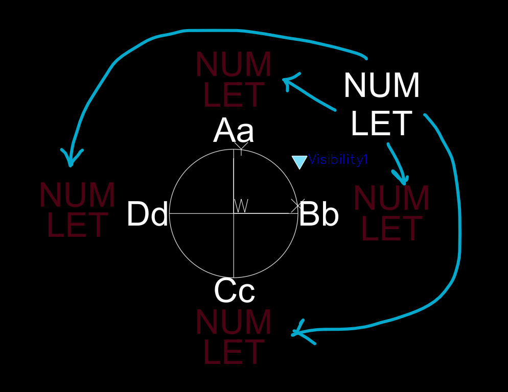
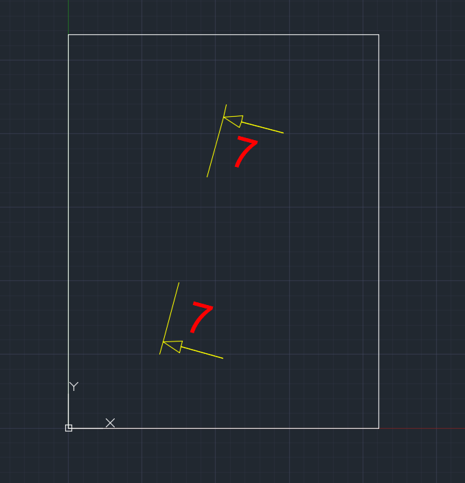
Moving Attributes in a Dynamic Block I have a dynamic block with 5 display states. In 4 of the display states I need my attributes to be in different locations. I have shown the approximate location for each display state shown in a dark red color. I do not know how to move attributes within a dynamic block. If you insert the attached block in a drawing you will see what I have so far.. NUM / LET are the attributes If someone could please explain the procedure. TEST-DB.dwg
-
I'm almost there with my workflow, but I need a little help to get it just right. Here's what I'm trying to do: Type command Select block Pick Mleader arrow location Pick Mleader landing location Mleader content should automatically populate with the "SW_LENGTH" parameter from the block Everything works great up until step 5. After I pick both Mleader points, the Mleader text box opens for me to fill out (it's blank). But if I click in the drawing area, it exits the text box and fills in the correct info. So, how do I skip that last step and have the Mleader content fill in automatically without Autocad opening the text edit box? ;; Get Dynamic Block Property Value - Lee Mac ;; Returns the value of a Dynamic Block property (if present) ;; blk - [vla] VLA Dynamic Block Reference object ;; prp - [str] Dynamic Block property name (case-insensitive) (defun LM:getdynpropvalue (blk prp) (setq prp (strcase prp)) (vl-some '(lambda (x) (if (= prp (strcase (vla-get-propertyname x))) (vlax-get x 'Value))) (vlax-invoke blk 'GetDynamicBlockProperties))) (defun c:swtest () (setq blockName (car (entsel "\nSelect Block: "))) (if (and blockName (eq (cdr (assoc 0 (entget blockName))) "INSERT")) (progn (setq vlaBlock (vlax-ename->vla-object blockName)) (setq SW_LENGTH (LM:getdynpropvalue vlaBlock "SW_LENGTH")) (if SW_LENGTH (progn (setq textString (strcat "SW_LENGTH: " (rtos SW_LENGTH 2 2))) (princ (strcat "\n" textString)) (if (setq ins (getpoint "\nSpecify start point for MLeader: ")) (progn (setq endPoint (getpoint "\nSpecify end point for MLeader: " ins)) (setq curlay (getvar "CLAYER")) (setvar 'CMDECHO 0) (command "_.undo" "_group") (setvar 'CLAYER "S - TEXT") (command "CMLEADERSTYLE" "NORMAL - SW") (setvar 'CMDECHO 1) (initcommandversion) (command ".MLeader" ins endPoint "") (while (> (getvar "CMDACTIVE") 0) (command PAUSE)) (setq mleaderObj (vlax-ename->vla-object (entlast))) (vla-put-TextString mleaderObj textString) (setvar 'CMDECHO 0) (command "CMLEADERSTYLE" "Normal") (command "_.LAYER" "_SET" curlay "") (command "_.undo" "_end") (setvar 'CMDECHO 1) (princ "MLeader with SW_LENGTH created.")) (alert "Insertion point not specified!"))) (alert "SW_LENGTH attribute not found!"))) (alert "Selected entity is not a block!")) (princ))
-

Dynamic Blocks | Rotate Parallel Lines and Maintain Perpendicular Distance
bluebravo posted a topic in AutoCAD Drawing Management & Output
Hello! Quick FYI: (1) I am a brand new forum member, but I have looked up CAD issues on CADTutor various times! (2) I believe myself to be an intermediate level skilled CAD user Goal: I am trying to create a dynamic block of plywood that can be rotated, lengthened, and thickened. The block would contain two parallel lines and a hatch between them. I think I can achieve the lengthening with linear stretch and the thickening I can probably figure out, but I do need help with the rotation! Please see image for desired result: I have tried chained rotation actions, but the lines do not remain the same distance apart. Also, when all objects are rotated about the origin, the top line extrudes horizontally past the bottom (origin) which I do not want. I am not sure how wordy to be with my explanation, so I will leave it at this for now. Let me know if I need to provide anything else!
-
Is there a method to update blocks and nested blocks (dynamic and/or annotated without losing their position, visibility status, and annotated values: Tag/prompt/default values) based on new blocks that will contain in a folder (source files)? New blocks have the same block name as old ones. The cad block files within the "source" folder have the same name as the old block. Dynamic blocks have stretch or rotation properties, example: block is stretched to 2100mm and rotated to 30 degrees. 1) is it possible to obtain this kind of sophistication? 2) How would I run this routine without opening the drawing and that select the drawing files? Thanks
-

AutoCAD MAP3D import shape files with OD to fill attributed blocks
Sambuddy posted a topic in AutoLISP, Visual LISP & DCL
Not quite sure how to tackle this, because my options on the -mapimport is very limitted and did not completely understand ADE_ function library. When I use the dialouge box of mapimport, I do get options of "creating object data" in addition to "creating points as blocks" with the option of "getting attribute values from field". So I simply create a block and define attributes with the TAG to match the the "Attribute Table" from QGIS and everything works as it should - that is I now have blocks that show the values for each block because I selected "Get attribute values from field" on Mapimport dialouge box. Can it be possible to have a routine that automate this process to 0) select a folder that contains multiple shape files and not selected one by one 1) import the map (lines and points) 2) lines and maps to be imported with their respected Object data 3) dynamic blocks be inserted that contain attributes to show the OD values at each imported points 4) visibilities of the blocks change with values/ attributes (example: if value is Hydro then visibility A and if Telecom then visibility B)? so here on this code, I am selecting a folder and then reading the content (shape files), but then I cannot go further because -mapimport did not give me all the options needed. also Block_1 and Block_2 are just examples of a block/ currently with no visibility for the conditions stated above. I do not work with Map3D all that often so help is appreciated! ( (lambda ( / path);lstall lstseluser (defun BrowseForFolder ( / sh folder folderobject result) (vl-load-com) (setq sh (vla-getInterfaceObject (vlax-get-acad-object) "Shell.Application")) (setq folder (vlax-invoke-method sh 'BrowseForFolder 0 "" 0)) (vlax-release-object sh) (if folder (progn (setq folderobject (vlax-get-property folder 'Self)) (setq result (vlax-get-property FolderObject 'Path)) (vlax-release-object folder) (vlax-release-object FolderObject) result ) ) ) (if (null (setq path (BrowseForFolder))) ;; just in case you didnt specify a path nil (setq lstall (vl-directory-files path "*.shp" 1))) ;---------------------------------------- ;; msg - [str] Dialog label ;; lst - [lst] List of strings to display ;; bit - [int] 1=allow multiple; 2=return indexes ;; Returns: [lst] List of selected items/indexes, else nil (defun LM:listbox ( msg lst bit / dch des tmp rtn ) (cond ( (not (and (setq tmp (vl-filename-mktemp nil nil ".dcl")) (setq des (open tmp "w")) (write-line (strcat "listbox:dialog{label=\"" msg "\";spacer;:list_box{key=\"list\";multiple_select=" (if (= 1 (logand 1 bit)) "true" "false") ";width=50;height=15;}spacer;ok_cancel;}" ) des ) (not (close des)) (< 0 (setq dch (load_dialog tmp))) (new_dialog "listbox" dch) ) ) (prompt "\nError Loading List Box Dialog.") ) ( t (start_list "list") (foreach itm lst (add_list itm)) (end_list) (setq rtn (set_tile "list" "0")) (action_tile "list" "(setq rtn $value)") (setq rtn (if (= 1 (start_dialog)) (if (= 2 (logand 2 bit)) (read (strcat "(" rtn ")")) (mapcar '(lambda ( x ) (nth x lst)) (read (strcat "(" rtn ")"))) ) ) ) ) ) (if (< 0 dch) (unload_dialog dch) ) (if (and tmp (setq tmp (findfile tmp))) (vl-file-delete tmp) ) rtn ) (if (not (= lstall nil)) (setq lstseluser (LM:listbox "Select one or more shape files (Ctrl or Shift):" lstall 1)) ) ;---------------------------------------- (if (not (= lstall nil)) (progn (alert (vl-prin1-to-string lstseluser)) ) ) ) ) -

Generating a "Table Row" block
DJAW posted a topic in AutoCAD 2D Drafting, Object Properties & Interface
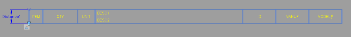
Working to standardize a bill of material drawing that must consist of nothing more than text, lines, and blocks for a client that refuses to use datalinks and I was hoping to find a way to create a standard block that could act as a row in the table with cells containing text fields. Essentially, I would like to have the functionality of attribute definitions but have them copy down using some kind of array action. Has anyone had any luck/experience with something like this? I understand it's might be kind of impossible. Attached is what I'm hoping to have as default text in the newly generated row as the user pulls down the array arrow.
-

dynamic block Dynamic parameters destroyed when copied to another drawing
grzegorz1928 posted a topic in AutoCAD Drawing Management & Output
Hi, I have a problem with copying a reference to a dynamic block from one drawing to another drawing containing the definition of the same block - their dynamic parameters are not preserved correctly. Comments: If I insert this block into a "clean" drawing, this problem does not occur. When I change the MIRRTEXT variable, the block looks different after pasting, but still incorrect. The procedure "_copyclip -> _pasteblock" does not solve this problem either. Copy: Paste: Thank you in advance for your help. base.dwg insert.dwg
-

Dynamic block rotation (with fillet)
adylon posted a topic in AutoCAD 2D Drafting, Object Properties & Interface
Hi everyone, I am trying to make a block with a rotation parameter. Two lines connected with a rounded corner. One line you can rotate. The arc follows the rotation but should adjust accordingly to the angle between the lines, the radius stays constant. Can someone give me a kickstart to solve this?? RotationBlock_withFillet.dwg -

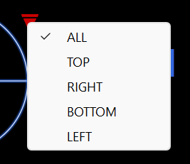
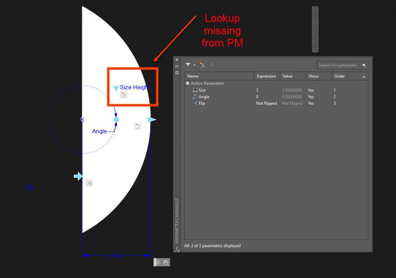
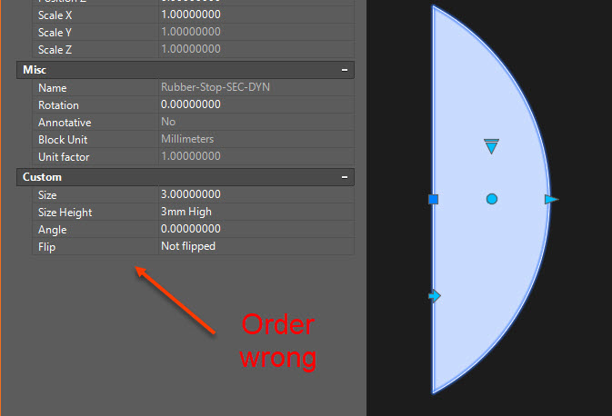
Sort order of Dynamic block parameters. Lookup missing from Parameter Manager
3dwannab posted a topic in AutoCAD Drawing Management & Output
See screenshots. How do I place the lookup in an ordered manner? Thanks in advance.
-
 I'm modeling a dynamic block. It represent a simple floor plan chimney. The dynamic block has six stretch actions. Three stretch actions are displayed in the properties menu. Two strectch actions have grip points. The total width and length. Tree stretch actions are chaind. They stretch with the wall thickness action. Unfortunately they won't move equal. Drawing1.dwg
 -

dynamic door Dynamic door block flip and stretch error
mickeforsberg posted a topic in AutoCAD Drawing Management & Output
Hello! I'm trying to create a dynamic door with a 25 degree opened angle, however, I also want to be able to stretch the door while flipped horizontal/vertical. This is where I'm having trouble. I can only stretch the width of the door if both or none of the axis are flipped. If I flip it horizontally the door leaf does not stretch in the same angle. Does any body know how to correct this? I have checked the sample doors in Autocad that are opened 90 degrees, and they work with flipping. Not sure if it has to do with the 90 degrees or some other thing they have done. As a bonus, if you could help me with one other thing... I also would like it if the flip would continue to stay centered even if I stretch the width or depth. So if I stretch the door from 700mm to 900mm it would not offset when flipping it, and if I would change the depth of the door it would stay centered on the wall. Please point me in the right direction if you could! DWG of the door is attached. Thanks! dynamic_door.dwg -
Hey, I draw ventilation ductwork all day at work, just recently stumbled across dynamic blocks and could do with a little help with one. Attached is what i have done so far, the straight section works perfectly, just having some trouble with the radius bend. What I need is for the arc to stretch with the angle of the bend. :/ I appreciate any help, and feel free to use my working block. TEST.dwg
-

Help creating an expanding Dynamic Block
muzicman82 posted a topic in AutoCAD Drawing Management & Output
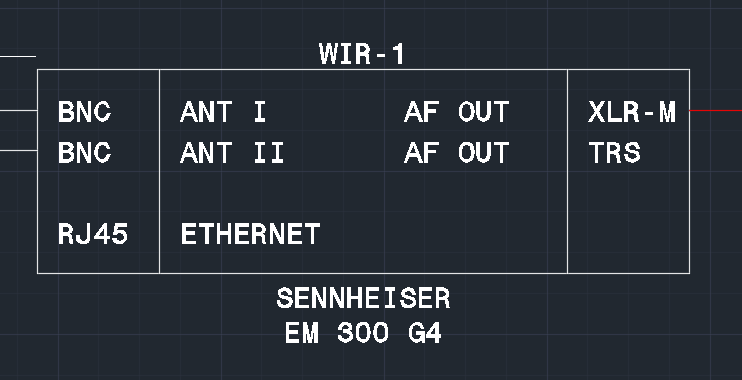
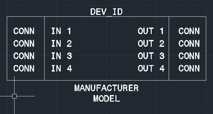
Hi all, I'm not new to AutoCAD but I've honestly never created a dynamic block and don't know what I need to do. I've watched a few tutorials on dynamic blocks but what I am trying to do seems a little different than the typical use-case. I do a lot of audio-visual one-line drawings in AutoCAD. I have device equipment blocks showing all input and output connectors. I manually make them for every device but am looking to have a go-to generic dynamic block for one-off simple devices. Here are examples of finished manually created blocks: However, what I am looking for is a block that dynamically transform from this: To this: Ideally, block parameters would define how many "lines" of connections there is. Or, I am guessing there is a way for the block to be stretched such that the lines of connections become visible, but I do not want free stretch. The bottom edge of the rectangle should be a specific spacing from the middle of the last line of text. I'm sure the text could be shown or hidden with visibility, but then I don't understand how I'd resize the rectangle as required. Attributes can allow text for NAME and CONN for each IN/OUT. The manufacturer, model, and DEV_ID are all attributes. If for example there are a different number of inputs/outputs, I imagine just leaving the text attributes blank is enough to effectively hide them. If there's videos on doing this sort of dynamic block, links are appreciated. Most of the videos I've found are discussing layout/graphic objects. Thanks!
-

Dynamic block - Horizontal text and stretch constraints
andrea-alfiere posted a topic in AutoCAD Beginners' Area
Hi all! I came out with a problem in the last days, which I wasn't able to solve at all. It's about the creation of a dynamic block of a door, which features stretch, move, polar stretch and rotate commands. I reviewed, with great benefit, already several blogs, but this problem has a different issue which I hadn't found discussed yet. The main problem I am experiencing is how to keep the door tag horizontally, while rotating the door (problem which I solved), meanwhile (the Tag) it must stay fixed in the middle of the opening, even when I am scaling the door (problem which I haven't solved). I am attaching three blocks: 1) DOORTAG_0 is the main file I created with all the features I would like to keep for the door (it lacks, basically only of the possibility to be rotated) 2) DOORTAG_1 is a first attempt about how to solve the problem (it is possible to rotate the door keeping the text horizontally but impossible to keep it in the centre when scaling) 3) DOORTAG_2 a second attempt which I solved with polar stretch. However this structure of commands doesn't allow me to properly scale the door. If someone could check this issue, or have a look at my file, it would be so much appreciated, and surely of great help. Thousands thanks in advance, Andrea. DOORTAG_0.dwg DOORTAG_1.dwg DOORTAG_2.dwg -

Proportional stretch/scale dynamic block and lookup
BigThumper posted a topic in AutoCAD Drawing Management & Output
I'm trying to figure out how to accomplish this. I *think* I'm able to do it via block properties - but I'd rather not use a block properties table if I can avoid it. If only because there's a limit of 1 block properties table per block and I want to save that for other purposes. Attached is a sample block. It's just a square with a notch in one side, filled with a hatch. Using the lookup table, and the defined stretch actions, I can grow the block to any of the desired 4 sizes. But I want more. I want grips that will let me re-size the block by dragging - but it needs to retain the proportions. If I drag in the Y axis, the X-axis doesn't update. If I pull the left side, the right side doesn't update (and neither does the Y axis). I've tried various combinations of stretch, scale, and constraints - so far I've come up empty. StretchSample.dwg -
I am attempting to create a Dynamic Block for electrical home runs that behaves similarly to home runs in Revit. Essentially it is a Spline with (3) Control Vertices and an Arrowhead at opposite end from the Basepoint. I have created the Dynamic block to include the desired visible elements and I've gotten the Spline to behave correctly using Stretch Actions. The only problem I am having is that I can't get the Arrowhead to follow the end of the Spline correctly. I would like it to "bend around" with the Spline but it wants to stay at a fixed angle. If anyone can point me in the right direction (pun intended) or modify the attached example of my Dynamic Block, that would be appreciated. Also, I am aware there is an Mleader Style that utilizes a Spline instead of a straight line. However, the Spline is based on Fit Points instead of Control Vertices and simply does not behave the way we need it to, thus the reason for the Dynamic Block. HOME-RUN.dwg
-

steel structure Dynamic Block of Steel Shapes (Metric)
jamildear4u posted a topic in Blocks, Images, Models & Materials
All Steel Shapes with different environment now in one block. Shapes>>> Beam,Channel, Tee, Equal/Un-Equal Angle Environment>>>American, European, British, Japanese Download Block: https://jentertain.blogspot.com/2019/12/dynamic-block-of-steel-shapes-metric.html- 4 replies
-
- 2
-

-
- 2d dynamic block steel shapes
- dynamic block
- (and 1 more)
-
development Dynamic Block of Cylinder Cut Development
jamildear4u posted a topic in Blocks, Images, Models & Materials
I have shared a Dynamic Block and you can download through the link below and also can watch video that demonstrate it how to use 2D dynamic block to develop a flat pattern of a cylinder that has been oblique Section. Dynamic Block Download Link -
2d dynamic block Dynamic Block Vessel Dish head
jamildear4u posted a topic in Blocks, Images, Models & Materials
Dynamic Block Pressure Vessel Dish head 2:1 Elliptical head Dish Head All Types.dwg -
flanges b16.5 Dynamic Block Flange B16.5
jamildear4u posted a topic in Blocks, Images, Models & Materials
Dynamic Block of ASME B16.5 Flanges Rating 150# 300# 400# 600# 900# 1500# 2500# Sizes From 1/2" to 24" Watch The video of Dynamic Block Block https://www.youtube.com/watch?v=sdFtOPWggFo ASME B16.5 Flange Plan.dwg -
Hi, I need your help on creating a dynamic block of a steel roof. Here is the basic element of the steel roof which I need to repeat, the hidden line being the beginning and ending of the steel sheet. I have tried the array action without success. My only solution is to use xclip on an imaginary large steel roof but doing it with a dynamic block will be just great. Thanks. Steel Roof Dynamic Block.dwg