All Activity
- Past hour
-

Having some issues converting to 3d
TimC replied to TimC's topic in AutoCAD 3D Modelling & Rendering
Just to be clear, I don't mean that the way you did it was wrong. I mean, what can I change earlier in the project to make this part easier? I reread what I wrote and it definitely didn't sound like I meant it to -
Having some issues converting to 3d
TimC replied to TimC's topic in AutoCAD 3D Modelling & Rendering
So this is something I want to set up so that I can do multiples and just change the name and number. What's the easiest way to go about this? Doing what you did, seems like there's gotta be an easier, more efficient way from the begginning...lol - Today
-

Having some issues converting to 3d
BIGAL replied to TimC's topic in AutoCAD 3D Modelling & Rendering
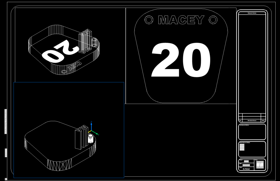
Ok I used Txtexp on "MACEY", then went to a 3d view so could see what was going on VPOINT -1,-1,-1. You have to check that all the objects that appear are plines I had to join the little "A" triangle. Ok extruded the base 1.5 Extruded the circles 2.5, then unionid both, to base, subtracted the inner circle from the new solid. Extruded the ""M" 4.5 then did a union again. Extruded the two parts of the "A" unioned together with base then subtracted the inner triangle, You can see the progress. What you want is not a single step but rather multiple steps, lastly can export the STL file. Once you get the hang of extruding, subtrcat and union you can do multiple objects at one time. This is a bit rough as a solid and can be done better, by moving the text to a Z matching base height before you start.
- Yesterday
-
LISP CODE INSERTING ELEVATION FROM CIVIL 3D SURFACE TO 3DPOLYLINES
BIGAL replied to darshjalal's topic in AutoLISP, Visual LISP & DCL
Why not just use the inbuilt "FEATUREELEVSFROMSURF " -
Having some issues converting to 3d
TimC replied to TimC's topic in AutoCAD 3D Modelling & Rendering
Sorry it took so long to get back. I never got notifications that there were any replies. OK, so maybe I'm missing something here and ChatGPT and Gemini are of zero help so far. I have this drawing. I'm trying to make a 3d printed ATV number plate. Extrude absolutely won't work for me, not sure why. I was able to use the "presspull" command to punch out the holes (which I don't believe is the correct way) and I can raise the plate up the 3mm I want and the support around the holes the additional 1mm I want but it absolutely won't do anything with the text. I tried MTEXT and single line text. Neither works My printer is a FlashForge AD5X Mark Macey Rear Plate.dwg -
 MSHR joined the community
 -

LISP CODE INSERTING ELEVATION FROM CIVIL 3D SURFACE TO 3DPOLYLINES
darshjalal posted a topic in AutoLISP, Visual LISP & DCL
3PS.LSP -
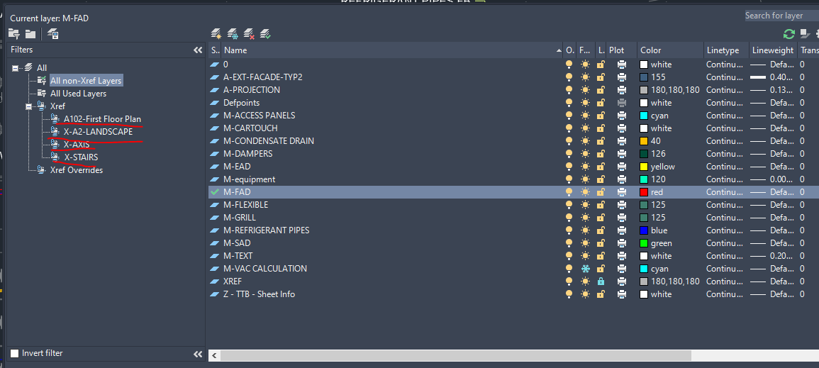
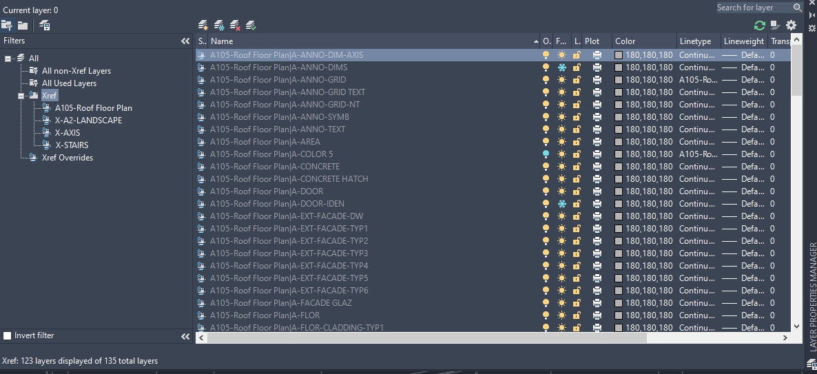
Hi Again for example, here I have 4 xref attached, I need to change the layers properties (make color 180,180,180 and line weight =default) for these xrefs without opening all drawings. Thank you for your time
-
 jalalmahmoud joined the community
 -
Set Pline Z value by selecting text
darshjalal replied to PaulyPHI's topic in AutoLISP, Visual LISP & DCL
PETA-INSERT ELEVATIONS FROM TEXTS INSIDE THE CLOSED OR OPEN POLYINE.LSP Try this one too - Last week
-
 Nymex joined the community
 -
 aepsmith89 joined the community
 -
@ababs "actually we attach the architectural drawings as xref " so why not do the changes then as part of an custom attach xref lisp. Again need an idea of what the layer names are and the relevant changes. How do you propose to identify the layers ? By wildcards "wall*" etc Were I worked we redid the color of layers by wildcards about 7 of them. So maybe 50 layers.
-
 kedungwunguai joined the community
 -
hello actually we attach the architectural drawings as xref after finishing our mechanical plans we have to publish so we got to change xref's layers properties excpt for title block(which is also xref)
-
A routine automates the creation of 3D Polylines, level labels, and slope percentages for infrastructure projects (SUPPORTS FEATURE LINES TOO)
darshjalal replied to darshjalal's topic in AutoLISP, Visual LISP & DCL
Updating version of the previous code> Regards. 3DSLOPE-automates the creation of 3D Polylines, level labels, and slope percentages -R2.LSP -
You can use possibly OBDX which can edit a dwg without opening it. Using a script is much simpler as it will open a dwg make the edits then close it. Should be reasonably fast. The obvious first step is what are you trying to change ? You need say a text file with the new settings, layer name, color, linetype on/off and so on. So if I understand correct another way, the sequence may be open a dwg add the xref do the layer changes save and close do next dwg. So what I am asking here does original dwg always have the xref pre loaded. Need sample dwg, txt and a xref. Can be blank just need layers,
-

Civil drafting school project help
ReMark replied to Autocadstudent's topic in Student Project Questions
Definition: "Stationing in surveying is a linear measurement system used to pinpoint exact locations along a project's baseline or centerline. One full station equals 100 feet." It starts as 0+00 (0 feet) which in this case would be the center of the cul-de-sac and stops at the end of the project which would be station 3+78.90 (378.97 feet). In between there is station 0+50 for the point-of-curvature (PC), station 1+93.87 for the point of tangency (PT) along with stations 1+00, 2+00, 3+00 and any others deemed necessary to call out. -

Set Pline Z value by selecting text
pkenewell replied to PaulyPHI's topic in AutoLISP, Visual LISP & DCL
@PaulyPHI Give this a try.SetPlineZ_Updated.lsp -

Civil drafting school project help
EmeraldSynth replied to Autocadstudent's topic in Student Project Questions
I've seen that photo in this chat. I'm just confused about how to even start it . What is it referring to when it says for example "Station 2+20"? -
Hi, I have been racking my brains to amend this lisp to do what i want and have failed.... so i ask you the gods of lisp for some help. I have acquired a lisp file via google AI that will set the elevation (z axis) of a poly line, easier to just select the pline and type in the elevation i hear you cry.... But my cunning plan was to amend the elevation of said pline by selecting the pline then select the text/mtext next to it..... I thought i could add some command to do this by looking at another lisp i have that does a similar thing, but i am a numpty and have given up.... I know there are many wise men out there that could just type some lines with their eyes shut and solve my problem... Obviously i would be greatly indebted to such persons and wish boundless fortune upon them granting wishes galore if i could... Also I just want an easy life as i approach retirement and thinking for gets in the way of thinking for myself..... Begging you nicely.. Paul SetPlineZ.lsp
-
Civil drafting school project help
ReMark replied to Autocadstudent's topic in Student Project Questions
The driveway profile will look something like this.
-
Hi everyone, I’m working on a project with multiple AutoCAD drawings (building floors), and each floor contains several XREF layers. I want to know if there is a way or tool to change XREF layer properties (such as color, linetype, lineweight, etc.) for multiple drawings at once without opening each file individually. For example: I have many floor plans. Each drawing has the same XREF attached. I want to directly modify the XREF layer overrides across all drawings in bulk. Is there a built-in AutoCAD feature, script, LISP, Sheet Set method, Layer States Manager workflow, or Autodesk tool that can do this automatically?
-
 romzi joined the community
 -
 BABAR45 joined the community
 -
 froxen1 joined the community
 -
I forgot all about this thread, meant to get back to it. My apologies. Elmer FEM – open source multiphysical simulation software CALCULIX: A Three-Dimensional Structural Finite Elemente Program use with PrePoMax Structural Analysis & Steel Design Software | AutoCalcs Free Online 3D Structural Finite Element Analysis Software There are some more open-source and free programs out there. These have a free trial. Finite Element Analysis (FEA) Software | Autodesk Download Inventor | Inventor Free Trial | Autodesk FEA Simulation Basics | Autodesk Inventor 2023
-
Civil drafting school project help
EmeraldSynth replied to Autocadstudent's topic in Student Project Questions
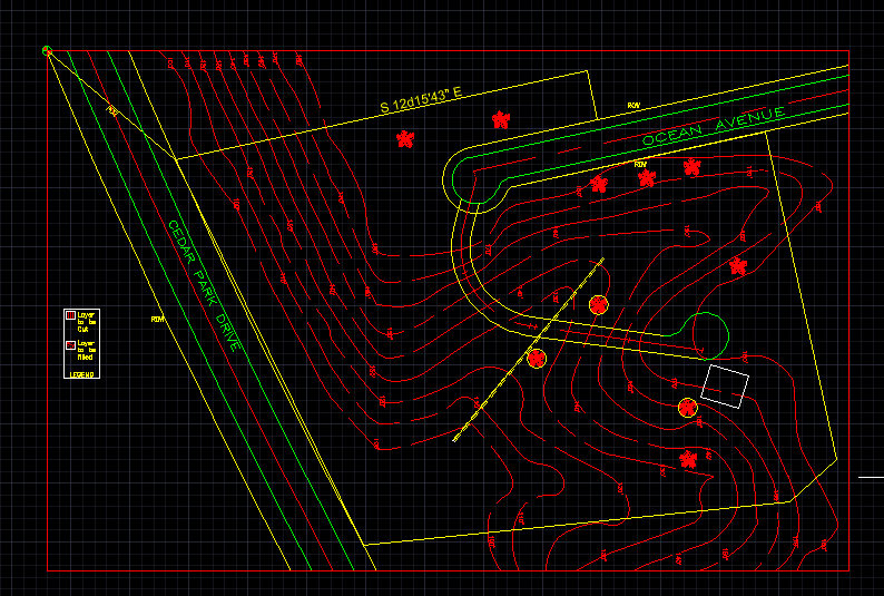
Hello all. Now I'm struggling with the same issues as everyone one else. So I've gotten to the cut and fill portion, and I'm stuck trying to figure out how to show this part of the instructions. Ms. Capitano decides to keep the driveway and the house level at elevation 180. Her surveying company recommends an angle of repose of 1.5:1. Draw the driveway layout cut and fill in the lower-left corner of your drawing. Use the information listed here to show the new contours on both sides of the driveway. How am I supposed to start off this, and how does the "angle of repose" factor in? Don't remember reading about that... Here's what my drawing looks like so far. Thanks!
-
From what I can tell, you don't need to specify a particular update of Civil 3D to get the right application code. For instance, "AeccXuiLand.AeccApplication.13.1" will work for any flavor of Civil 3D 2019. Then just add a 1 for each successive year. Civil 3D 2019: 13.0 Civil 3D 2020: 13.2 Civil 3D 2021: 13.3 Civil 3D 2022: 13.4 Civil 3D 2023: 13.5 Civil 3D 2024: 13.6 Civil 3D 2025: 13.7 Corrections/suggestions welcome. Of course, they'll break the sequence as soon as it becomes widely known and useful.
-
 zhorzh joined the community
 -
MultiPLine (MPL) — polyline-based MLINE replacement with per-line layers, presets, and auto-sync [Free + Pro]
BIGAL replied to SkillAmplifier's topic in AutoLISP, Visual LISP & DCL
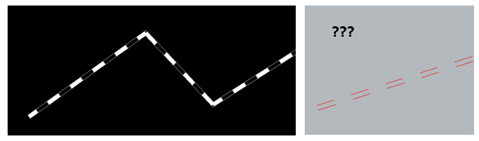
The equal linetype as supplied is just a dashed linetype that has a length of one unit and a gap of one unit. By setting its LTSCALE to the length of a pipe you can get an idea of the number of pipes involved. I have somewhere also convert an existing line to two lines as per right hand image, The GIS used to dump out a single line on a size layer so we wanted 2 dashed lines to imply existing drainage. Will try to find I think that is what you want. -

A toolkit is designed to streamline the conversion of raw survey texts ,and markers into professional MLeaders
Emmanuel Delay replied to darshjalal's topic in AutoLISP, Visual LISP & DCL
Hey, that's useful. I'm keeping this one- 1 reply
-
- 1
-

-

MultiPLine (MPL) — polyline-based MLINE replacement with per-line layers, presets, and auto-sync [Free + Pro]
Nikon replied to SkillAmplifier's topic in AutoLISP, Visual LISP & DCL
What should be the type of line to make a line like in the picture? If you use the EQUAL line type, you get just two dashed lines. The line type "Divide" is set in the code? (setq lt "Divide")
-

Having some issues converting to 3d
SLW210 replied to TimC's topic in AutoCAD 3D Modelling & Rendering
What 3D printer do you have? I just recalled, there used to be an APP at the Autodesk APP store, but no longer there, works on older AutoCAD, but it is also posted here at CADTutor and the Swamp. I use Bambu Labs and it comes with Bambu Studio which has a 3D Text that is very easy, I can do a custom name plate with text directly on the machine.