All Activity
- Past hour
-
hello: I've heard about the command OOPS Unfortunately, the AutoCAD I use at work is version 2013 Does anyone know if there is an LSP routine command for that? IT WOULD BE GREAT TO INCORPORATE IT Any advice is welcome. thanks
- Today
-

Top 20 AutoCAD Customizations – Part One: Tuesday Tips With Frank
The AutoCAD Blog posted a topic in AutoCAD Blogs
There are times when I discuss customizing AutoCAD, and I often receive a response similar to: “Oh, but I’m not a programmer.” No, no, no, you don’t have to be a programmer to set up AutoCAD to fit your workflow better, or in some cases, improve it. With that said, I present to you my list of top AutoCAD customizations for non-programmers. In this two-part series, the first 10 are included today. In no particular order, let’s kick it off. 1. Quick Access Toolbar Keep your most frequently used tools in the Quick Access Toolbar (QAT) at the top of your screen. Customize the QAT by clicking the small, pull-down control button on the right. You can check and un-check the commands you want quick access to. For a fast way to add a Ribbon command to the QAT, right-click any command icon on the Ribbon, and then select Add to Quick Access Toolbar from the pop-up menu. Similarly, right-click on any Quick Access Toolbar item to remove it. 2. Clean Screen Need to max out your screen space? CTRL-0 is your friend. The Ribbon and Palettes will be hidden, and AutoCAD will maximize to fill the entire screen. The QAT will remain on, so make note of the previous tip. CTRL-0 again to toggle it back. Of course, you can use the icon on the status bar as well. 3. Anchor Palettes AutoCAD’s many palettes are wonderful productivity enhancers, but not so great when they get in your way. Keep your favorites available with a simple mouse rollover by anchoring some left and some right. They take up almost no space when anchored, so you can still access their functionality while keeping your drawing editor clean and visible. 4. Right-Click Delay Do you still use your mouse right-click as Enter? If you’re not using the contextual pop-up menus when you right-click, you’re missing out on one of my favorite productivity enhancements. If you just can’t give it up, you can still have the best of both worlds by utilizing the time-sensitive right-click feature. You’ll find its control in the Options dialog, and when enabled, right-click will still function as you prefer, but now, by holding down the mouse button just a little longer, you’ll get the contextual pop-up menu instead. 5. Command Alias An AutoCAD command alias is a shortened name or abbreviation of a command name. Don’t like a default alias name? Change it! It’s easy. For example, a lot of people prefer C to be Copy instead of Circle. Does one of your often-used commands not have an alias? Add it yourself. Aliases live in a file called acad.pgp. And here’s the thing – it’s your .pgp file, not anyone else’s, so you can define them as you please. I’m a firm believer that using aliases and keyboard shortcuts, in conjunction with not taking your eyes off your work, is the best way to increase your speed and efficiency. Personally, I like to keep my most-used aliases mapped to the left side of the keyboard. That way, I don’t have to take my hand off the mouse or my eyes off my work to find a letter on the right side of the keyboard. 6. Places Stop wasting time by continually navigating multiple levels of folders in the File Open dialog box. Once you get to your folder, add it as a new entry in the Places pane of the Open dialog. Click on “Tools” in the upper-right corner, then select “Add Current Folder to Places.” A new icon will appear with the name of the folder. Now you can click on your new Place to jump right to that folder. If you find that you have multiple icons with the same name – “CAD,” for instance – just right-click on the icon, select Properties, and change the name to something that makes more sense, such as the project name. 7. Ribbon States The Ribbon doesn’t have to take up so much real estate. You can minimize it down to either panel buttons, panel tabs, or just titles. Decreasing the Ribbon’s footprint doesn’t affect its functionality, and it may just improve yours. 8. Floating Editor Have you ever had to work on one drawing while referencing another? You might want to take advantage of pulling your file tab off of the application, and to another location (such as another monitor). Don’t worry about losing any functionality either. The floating window has its own Command Line, and you can still use the Ribbon and Quick Access Toolbar from the main application while in your active floating window. When you’re done, use the title bar to drag it back to the file tabs area, or if you prefer, you can right-click the title bar, where you’ll find commands to either move it back. 9. Multiple Workspaces Do you work in multiple ways in AutoCAD? One day, you’re doing schematic drawings, such as wiring diagrams, and the next, you’re laying out 3D piping. Set up a separate workspace for your various workflows, containing the tools and palettes you need for the job. 10. Command Line Options AutoCAD’s Command Line is no longer just a utilitarian device to input commands. Now, it’s a multi-functional digital assistant that you can customize to match your preferences. Click on the wrench icon, and you can find tools to change your input settings, prompt history, and search options. It’s all just a wrench-click away! What’s Next? Stay tuned for the next installment to learn more AutoCAD customizations! More Tuesday Tips Check out our whole Tuesday Tips series for ideas on how to make AutoCAD work for you. The post Top 20 AutoCAD Customizations – Part One: Tuesday Tips With Frank appeared first on AutoCAD Blog. View the full article -

Civil Drafting with AutoCAD Project-Civil Drafting with AutoCAD Project
ReMark replied to nelsonm's topic in Student Project Questions
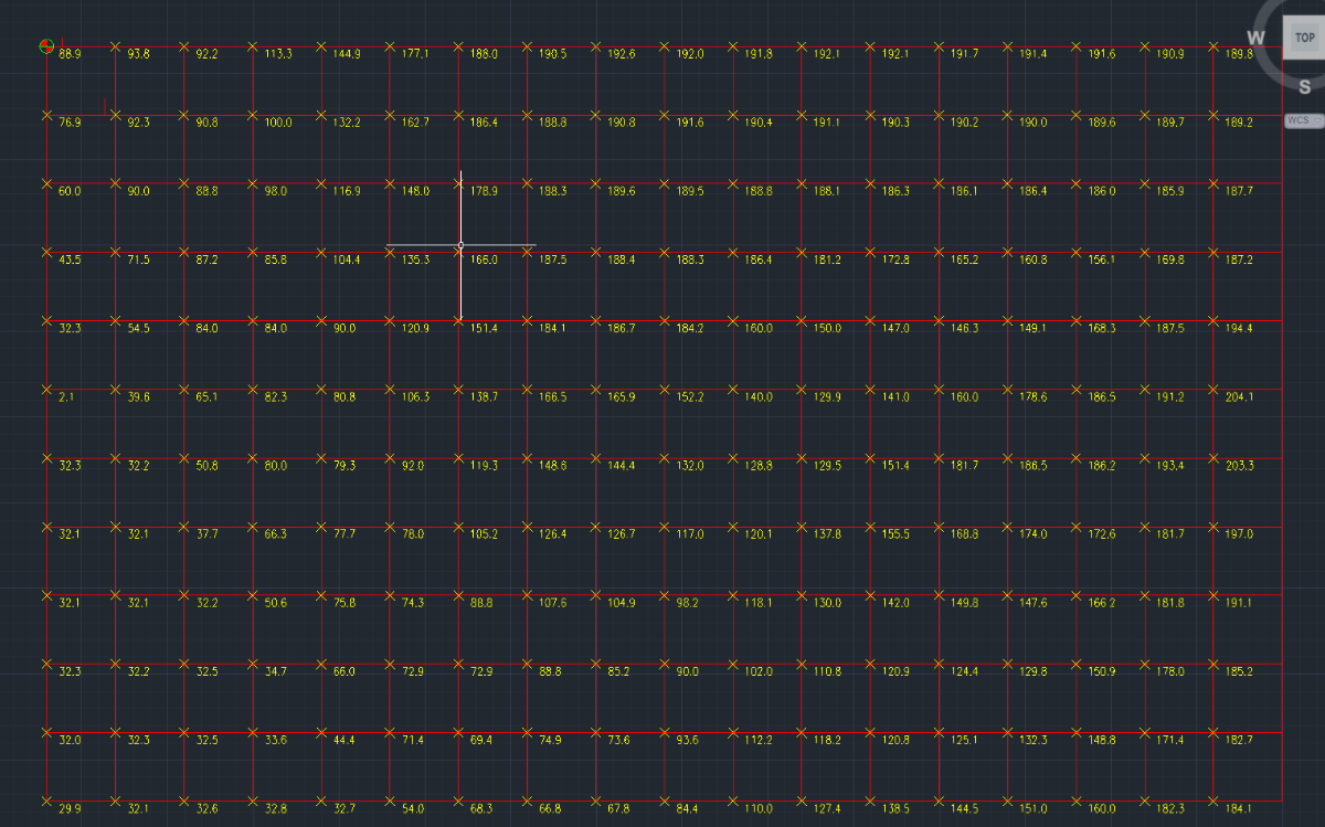
Your points will fall on the grid lines not inside the boxes created by the grid lines. -

Dynamic Blocks corrupted after a while of usage in ZWCAD
cad_tutee posted a topic in AutoCAD Drawing Management & Output
For context, I am using ZWCAD 2024 currently and I've created a dynamic block to be used in ZWCAD as an alternative to Multi-leaders to be an easier method to be able to DATAEXTRACT because my ZWCAD does not allow data extraction of MTEXT and MLEADERS unlike AutoCAD. I'd made the Dynamic Block to work exactly like a multileader would using, along with other parameters, Multiple Lookup Tables for rotating, extending and flipping the leader without affecting the order of text. That means they had to be created in licensed AutoCAD because ZWCAD's counterpart Flexiblocks do not have the LookUp parameter yet. The blocks worked normally as intended for a while on regular usage(working on, closing and reopening the file multiple times), but they stopped behaving like a dynamic block altogether suddenly after a few days on reopening the file. The blocks now seem to have been assigned different names by the software (*U15, *U16, and so) from its original name(m-Drawing M-Leader Block). I have attached the files below: Issue.dwg - File with the problematic Dynamic Blocks MultileaderDynamicBlock.dwg - File with the original Dynamic Block I have noticed this behavior with some other dynamic blocks in the files that I receive from consultants once in a while. Is this because of using dynamic blocks created in AutoCAD in ZWCAD? If yeah, why do they work perfectly for a while only to stop working all of a sudden? Is there a way to reverse this? I'd tried to replace the corrupted blocks with the original dynamic block reference, which would have itself been sort of a tedious task as there were so many instances in the drawing, but ZWCAD no longer recognizes the corrupted blocks as "blocks". ChatGPT and other LLMs are of limited help, so please help a brother understand and, if possible maybe, correct this issue. Or is there an alternative to this? Cheers! Issue.dwg MulltileaderDynamicBlock.dwg -
cad_tutee joined the community
-
 Zar joined the community
 - Yesterday
-
Oh that's cool, thanks for that lrm that will save quite a few steps in my process! Thanks again
-
Bit odd yes tested in Bricscad, I will look at the getcellextents, this gives the XY position of the corners of the table cell. If the line is 69 times repeated it sounds like that is the problem. I will make a little test program so can look at what is going on when calculating the Pt1 and Pt2. the code is done that way so if row height is changed for other users the lines are still central in the cell. Add the (princ line and look at the Y value displayed, it should change for every row. Please let me know if it is not changing. (setq pt2 (list (nth 6 pts)(nth 7 pts) 0.0)) (princ (strcat "\n" (rtos (cadr pt1) 2 3) " ")) (setq vdist (/ (- (cadr pt1) (cadr pt2)) 2.0)) Another test could some one try on Acad. 0 is 1st column. (setq objtable (vlax-ename->vla-object (car (entsel "\nPick a table ")))) ; put a number like 3+ in row variable ; then copy this line to command line change the 3 etc to 4 5 6 and so on ; The Y value should change (setq pts (vlax-safearray->list (vlax-variant-value (VLA-GETCELLEXTENTS objtable 3 0 :vlax-false))))
-
Works with BricsCAD. I know you have to wrap points in AutoCAD sometimes with (vlax-3d-point pt2) not sure about entmake tho.
-
 annegrpan31 joined the community
 -
 BHUTUU joined the community
 -

Bolted Connections and Bracings SolidWorks Structure System
mhupp replied to gabriele_biag's topic in SolidWorks
I don't work with this feature alot so might not be the best to answer this. the double L is two single L's just one is rotated. https://www.youtube.com/watch?v=57wTY5b8qcc&t=635s -
We bought a user at work a copy of CMS IntelliCAD a few years ago that just needed CAD every now and then and so far it was a great buy. For it's price it's hard to beat.
-
@lamensterms I'm glad you found spline curvature VLISP program helpful. Here's another program that you may find useful. It creates an arc through three point that may lie in 3D. Note, the ucs command would not use the 3 world points to correctly define the ucs I wanted so I had to use the more complex Z axis method in VLISP. ; create an arc through 3 points in 3D space ; lrm 3/9/2026 (defun c:arcIn3D( / p1 p2 p3 zpoint p1u p2u p3u) (command "_ucs" "w") (setq p1 (getpoint "\nPick start of arc: ") p2 (getpoint p1 "\nPick next point for arc: ") p3 (getpoint p2 "\nPick end point of arc: ")) (setq zpoint (mapcar '+ p1 (cross (mapcar '- p2 p1) (mapcar '- p3 p1)))) (command "_ucs" "za" "_non" p1 "_non" zpoint) (setq p1u (trans p1 0 1) p2u (trans p2 0 1) p3u (trans p3 0 1)) (command "_arc" "_non" p1u "_non" p2u "_non" p3u) (command "_ucs" "w") (princ) ) (defun cross (a b / crs) ; cross product of vectprs a and b (setq crs (list (- (* (nth 1 a) (nth 2 b)) (* (nth 1 b) (nth 2 a)) ) (- (* (nth 0 b) (nth 2 a)) (* (nth 0 a) (nth 2 b)) ) (- (* (nth 0 a) (nth 1 b)) (* (nth 0 b) (nth 1 a)) ) ) ;end list ) ;end setq c ) ;end cross arc_in_3d_space.lsp
-
Wow nice that looks like a very interesting tool, thanks lrm Your understanding of my task is correct. And your suggested workflow is pretty much what I have been doing (except without your LISP of course), and I was using 3DFACE to allocate my 'flat' points. One of the biggest and time consuming challenges has been to determine which points I will use to fit the ARCs to, while also maximising fit accuracy and also smoothness of the transition to the next ARC. I think your routine will come on quite handy to help me decide where to finish 1 ARC and begin the next Thanks again for sharing!
-
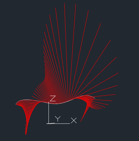
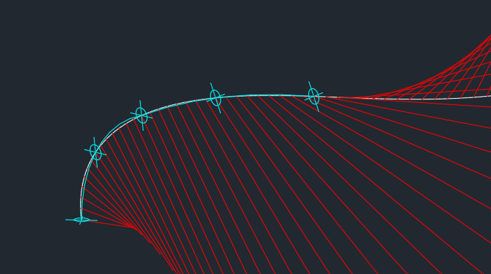
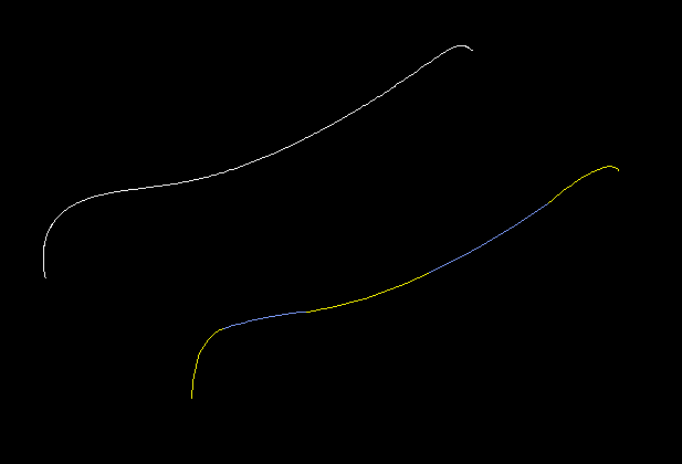
As I understand your question your goal is to approximate a 3D spline as a series of arcs (2d of course) that are positioned in series. To get a feel for the 3D nature and curvature of the spline I suggest first running my splinecurvature LISP program on the spline. Respond Y to the prompt: Do you want radius-of-curvature instead of curvature? [y/n] <n>: y and you will get a result like the following: The red lines are created at 100 points along the spline. They show the instantaneous radius of curvature of the spline at the points. The ends of the red lines are at the locations of the center of an arc that would duplicate the spline's curvature for a specific point on the spline. With this information you need to choose, starting at one end of the spline, 3 points along the spline that are in a generally "flat" area. Define a UCS for the 3 points then add an arc via the three point method. Repeat the process for the next "flat" section. Here are the results for two arcs. (defun C:SplineCurvatue (/ path inc n osm par der1 der2 curva p perp normv p2 sf curveType ans) ; = Degree Of Curvature - Lines ; Creates curvature lines or radius-of-curvature lines ; normal to a spline. ; LRM 8/18/2022 edited to place curvature vectors outside (setq path (car (entsel)) inc (/ (vlax-curve-getEndParam path) 100) n 0 osm (getvar 'osmode) ) (setvar 'osmode 0) (setvar "cmdecho" 0) (initget "y n") (setq ans (getkword "Do you want radius-of-curvature instead of curvature? [y/n] <n>: ")) (if (= ans "y") (setq curveType 1) (setq curveType 2 sf (getdist "Enter scale factor.") ) ) (repeat 100 (setq par (* inc n)) (setq der1 (vlax-curve-getfirstDeriv path par) der2 (vlax-curve-getSecondDeriv path par) ) ; calculate curvature at point par (setq d (distance '(0 0 0) (cross der1 der2))) (if (> (abs d) 1.0e-15) (progn (setq curva (/ (expt (distance '(0 0 0) der1) 3) d)) (if (= curveType 2) (setq curva (* -1. (* sf (/ 1. curva)))) ) (princ "\n") (princ n) (princ " curvature = ") (princ curva) (setq p (vlax-curve-getPointAtParam path par) perp (unitv (cross der1 (cross der2 der1))) normv (mapcar '* perp (list curva curva curva)) p2 (mapcar '+ p normv) ) (command "_.line" p p2 "") ) ; end progn ) (setq n (1+ n)) ) (setvar 'osmode osm) (setvar "cmdecho" 1) (princ) ) ;;; Compute the cross product of 2 vectors a and b (defun cross (a b / crs) (setq crs (list (- (* (nth 1 a) (nth 2 b)) (* (nth 1 b) (nth 2 a)) ) (- (* (nth 0 b) (nth 2 a)) (* (nth 0 a) (nth 2 b)) ) (- (* (nth 0 a) (nth 1 b)) (* (nth 0 b) (nth 1 a)) ) ) ;end list ) ;end setq c ) ;end cross (defun unitV ( v / d) (setq d (distance '(0 0 0) v) d (mapcar '/ v (list d d d)))) SplineCurvature.lsp

-
Hey thanks for the reply The reason to convert to a small quantity of ARCs is because the SPLINE will become fabricated out of steel pipe. Fab method requires the shape to be fabricated from curved pipe segments. Unfortunately for this project, corkscrew/spiral pipe segments are not an option, so we are stuck with ARCs
-
Obviously, you can't use the original spline or you'd be doing that. It might help us to know why, though. I assume the goal is a 2D spline. Have you thought about starting with an actual spline? That way you can adjust the control points and their tangents, instead of using polyline arcs, which seems more complicated. If the goal is a 2D polyline, you can still draw it with a spline and then convert it to a polyline with SPLINEDIT. The more we know about your project, the better we can help. Right now I'm just guessing.
-
Another way to handle this issue is to define your title block as an AutoCAD block. That way the seal is already included. You put the seal on its own separate layer and turn that layer on when necessary. Another option is to use visibility states, so you only tap on a button to show the seal. But first, as the other answers suggest, clean up the seal block. That may take care of it.
-
If you want to do some thinking, this is the row that draws the line: (entmake (list (cons 0 "LINE") (cons 10 pt1) (cons 11 pt2) (cons 8 (cadr lay)))) work it out backwards from there and you might get close to what you want, need to adjust pt1 and pt2. Without looking properly I think BigAl has forgotten to increment something or a variable is set on the wrong side of a loop. Be good learning to see if you can get close?
-
Civil Drafting with AutoCAD Project-Civil Drafting with AutoCAD Project
ReMark replied to nelsonm's topic in Student Project Questions
BIGAL: I agree with you 100%. Unfortunately, Penn-Foster does not offer TIN software nor do they teach its use. And, unless a student has some basic knowledge of LISP to begin with, I doubt they would even think of taking advantage of its functionality. In this project the old way is the best the students can count on. Re: Points. The project is not being done in 3D; strictly 2D all the way. -
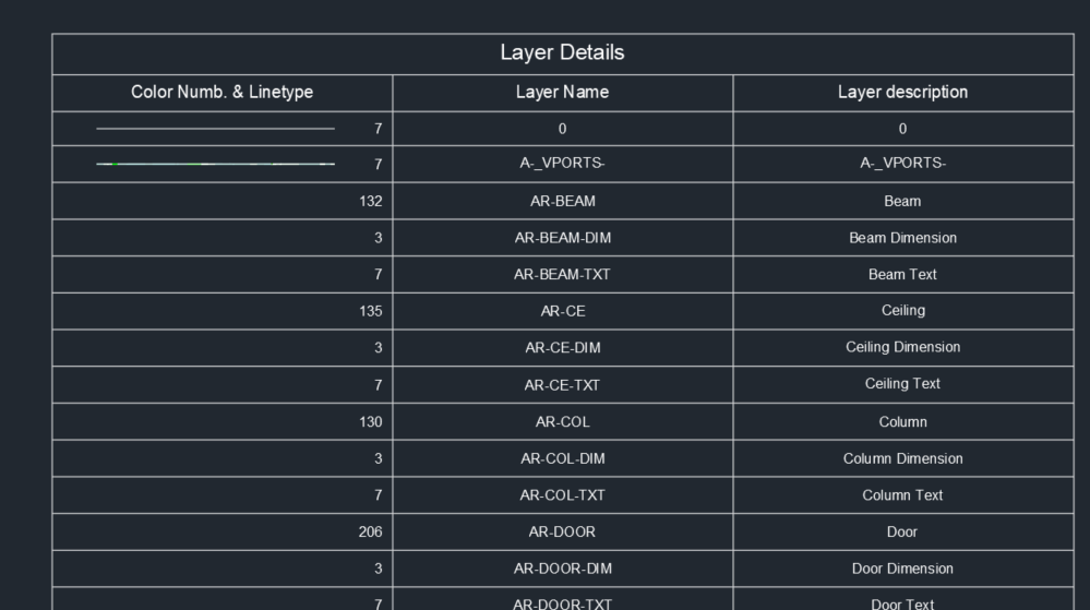
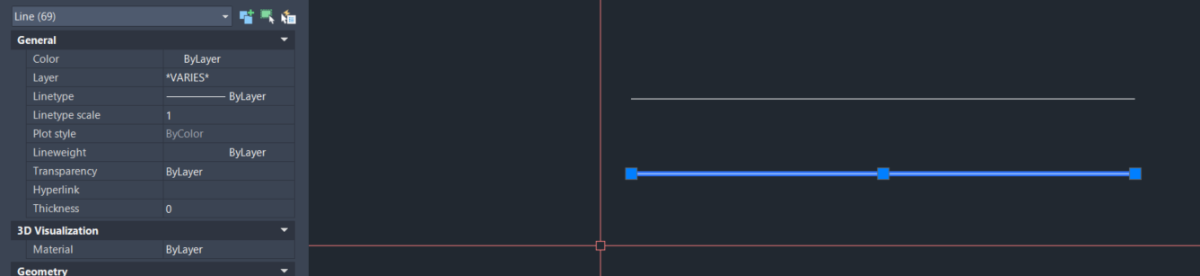
Thanks @BIGAL tested in AutoCAD 2024. some lines are not showing up. Anyway, the code by @nod684 works and it is according to my needs, Lines and Text not AutoCAD table. EDIT : I tried exploding the table and found that the 2nd line consists of 69 overlapping lines.
- Last week
-

Civil Drafting with AutoCAD Project-Civil Drafting with AutoCAD Project
BIGAL replied to nelsonm's topic in Student Project Questions
Welcome aboard, a little surprised that the exercise is to interpolate contour points. Given the availability of TIN software. That is a lot of points to tackle. Glad I am not doing that task. If I had to do it yes would use the method shown by @ReMark. But I would use a lisp to do the calculation making a Point at the correct distance then join all the points with a pline. I hope the little crosses are 3D so can pick pairs. Certainly have used the interpolation method in many other civil tasks, so well worth while learning how to do it. -
Hey, I've got a project that requires me to reproduce/trace a 3D spline, with ARC segments. The goal being to reproduce the SPLINE as accurately as possible, with as few ARCs as possible Just hoping to get some thoughts on methods to approach this challenge. Right now my method is to divide the SPLINE into sections based on the local normal-ness of part of the SPLINE. Just visually trying to fit each ARC to a portion of the SPLINE I have to perform this task 8 times for this project so hoping to come up with a neat and robust method DWG attached - in this example I am trying to work to a limit of 5 ARCs TEMP.dwg
-

Civil Drafting with AutoCAD Project-Civil Drafting with AutoCAD Project
nelsonm replied to nelsonm's topic in Student Project Questions
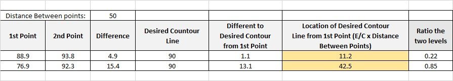
Thank you so much for you help! I made a spreadsheet in excel, can you take a look? and I have another question: how can I know in which squares to place the interpolations?
-
Civil Drafting with AutoCAD Project-Civil Drafting with AutoCAD Project
ReMark replied to nelsonm's topic in Student Project Questions
In other words, you are having trouble understanding the concept of interpolation, correct? The mathematical interpolation of contours goes like this. Let's say we have two spot elevations A & B. A = 32.7 and B = 54.0. The distance between A & B = 50 feet. We want to know where our 40-foot contour would fall between spot elevations A & B. First obtain the total elevation difference. This is done by subtracting A from B. 54.0 minus 32.7 = 21.3. Next, we want the difference in elevation between our 40-contour interval and the nearest spot elevation which in this case is A or 32.7. That works out to be 7.3. Now we need to calculate the distance (let's call this "d") we need to go from spot elevation A to our 40-foot contour. That takes the form of: d/7.3=50/21.3 or d=7.3*50/21.3 = 7.3*2.347 = 17.13 or the distance, in decimal feet, to our 40-foot contour. Got all that? Good. Now go start interpolating. -
 khoa2132005 joined the community
 -
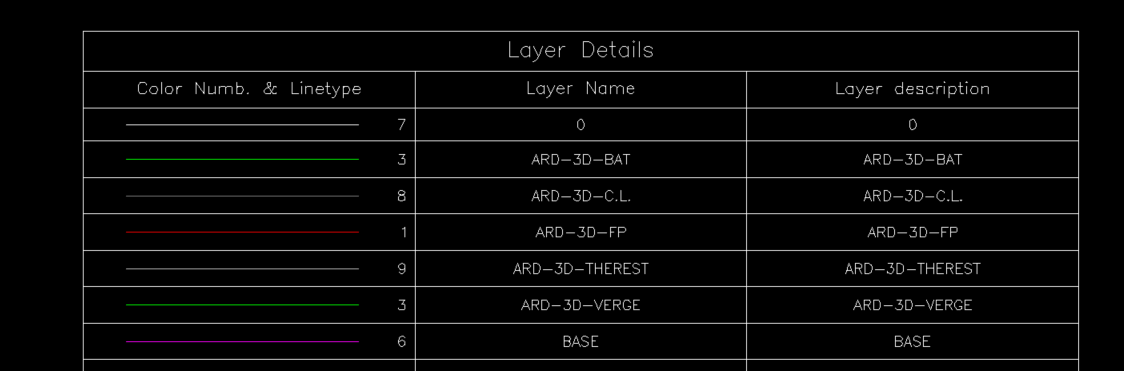
Almost there its a table fixed a couple of bugs and done. Tested on a dwg with 500 layers a little slow takes a few seconds. ; https://www.cadtutor.net/forum/topic/99017-layer-table-lines-and-text/ ; Make a lgend of layers in dwg. ; Bt AlanH March 2026 (defun c:mktablay ( / colwidth doc lay lcol ldesc lname lst numrows objtable oldsnap pt pt1 pt2 rowheight) (defun CreateTableStyle ( / dicts dictobj key class custobj dwglays ) (setq dicts (vla-get-Dictionaries (vla-get-ActiveDocument(vlax-get-acad-object)))) (setq dictObj (vla-Item dicts "acad_tablestyle")) (vlax-for dname dictobj (if (= (vla-get-name dname) "DWGLAYERS" ) ; does it exist (princ "Found DWGLAYERS") (setq dwglays "No") ) ) (if (= dwglays "No") (progn (setq key "DWGLAYERS" class "AcDbTableStyle") (setq custObj (vla-AddObject dictObj key class)) (vla-put-Name custObj "DWGLAYERS") (vla-put-Description custObj "Dwg Index custom table style") (vla-put-BitFlags custObj 1) (vla-put-FlowDirection custObj acTableTopToBottom) (vla-put-HorzCellMargin custObj txtht ) (vla-put-VertCellMargin custObj txtht ) (vla-SetAlignment custObj (+ acDataRow acHeaderRow acTitleRow) acMiddleCenter) (vla-SetTextHeight custObj acDataRow txtht) (vla-SetTextHeight custObj acHeaderRow (* txtht 1.2)) (vla-SetTextHeight custObj acTitleRow (* txtht 1.5)) (vla-SetTextStyle custObj (+ acDataRow acHeaderRow acTitleRow) "Standard") ) ) (princ) ) (setq oldsnap (getvar 'osmode)) (setvar 'osmode 0) (setq txtht 1.5) (CreateTableStyle) (setvar 'ctablestyle "DWGLAYERS") (setq lays (vla-get-layers (vla-get-activedocument (vlax-get-acad-object)))) (setq lst '()) (vlax-for lay lays (setq lname (vlax-get lay 'name)) (setq lcol (vlax-get lay 'color)) (setq ldesc (vlax-get lay 'description)) (setq lst (cons (list lcol lname ldesc) lst)) ) (setq lst (vl-sort lst '(lambda (x y) (< (cadr x)(cadr y))))) (setq pt (vlax-3d-point (getpoint "\npick a point for table "))) (setq doc (vla-get-activedocument (vlax-get-acad-object) )) (if (= (vla-get-activespace doc) 0) (setq curspc (vla-get-paperspace doc)) (setq curspc (vla-get-modelspace doc)) ) (setq numrows 3) (setq numcolumns 3) (setq rowht 5) (setq colwidth 50) (setq objtable (vla-addtable curspc pt numrows numcolumns rowht colwidth)) (vla-settext objtable 0 0 "Layer Details") (vla-settext objtable 1 0 "Color Numb. & Linetype") (vla-settext objtable 1 1 "Layer Name") (vla-settext objtable 1 2 "Layer description") (setq objtable (vlax-ename->vla-object (entlast))) (setq rowht (vla-getrowheight objtable 1)) (vla-put-regeneratetablesuppressed objtable :vlax-true) (setq row 2) (foreach lay lst (princ (cadr lay)) (vla-settext objtable row 0 (strcat (rtos (car lay) 2 0) " ")) (vla-setcellalignment objtable row 0 acMiddleRight) (vla-settext objtable row 1 (cadr lay)) (if (= (caddr lay) "") (setq desc (cadr lay)) (setq desc (caddr lay)) ) (vla-settext objtable row 2 desc) (setq pts (vlax-safearray->list (vlax-variant-value (VLA-GETCELLEXTENTS objtable row 0 :vlax-false)))) (setq pt1 (list (nth 0 pts)(nth 1 pts) 0.0)) (setq pt2 (list (nth 6 pts)(nth 7 pts) 0.0)) (setq vdist (/ (- (cadr pt1) (cadr pt2)) 2.0)) (setq pt1 (mapcar '+ pt1 (list 5.0 (- vdist) 0.0))) (setq pt2 (list (nth 3 pts)(nth 4 pts) 0.0)) (setq pt2 (mapcar '+ pt2 (list (- 7.0) (- vdist) 0.0))) (entmake (list (cons 0 "LINE") (cons 10 pt1) (cons 11 pt2) (cons 8 (cadr lay)))) (vla-insertrows objtable (setq row (1+ row)) rowht 1) ) (vla-put-regeneratetablesuppressed objtable :vlax-false) (setvar 'osmode oldsnap) (princ) ) (c:mktablay)
-
As I said previously "I am sure given that import a pdf and then re email the result back to you could be done by a friend as it takes like one minute." For that dwg maybe a few minutes, as suggested by @SLW210 do small bits at a time. @CHAKRADHAR It may cost you a little bit like cost of a cup of coffee. I can not help, Where are you in the world helps with time differences ? Some one here may be able to help. Did you contact ZWCAD, I know Bricscad are pretty good at listening to requests for missing functions.
-
Civil Drafting with AutoCAD Project-Civil Drafting with AutoCAD Project
nelsonm posted a topic in Student Project Questions
Hi, I'm a student from Pen Foster College and I have a trouble with this Project. I would like to get some help. For this part: Drafting the Existing Site Plan (Sheet 1): "Now, you need to figure out where the contour intervals cross the grid lines between each spot elevation. Create contours at 10′ intervals for just the 100′–180′ contour lines. You can estimate where a contour line intersects a grid line using interpolation. You can interpolate the position of the contours by estimating between the known locations of the spot elevations. You may find it quicker to set up a spreadsheet to help you calculate all the locations." Can someone guide me to get started with this part? please 3. Civil Engineering Drafting.pdf