All Activity
- Past hour
-
here's the AI reply to my question: "Activate Current Vertex 'X' marker: as if Clicking on the Current Vertex field on gis Properties, autolisp" here's the code and tried but my a2k might not be able.. can someone try this <short>Vertex.X.lsp? (defun c:Sv ( / ent obj vla-obj vertexNum) (vl-load-com) ;; 1. Select the polyline (setq ent (car (entsel "\nSelect Polyline: "))) (if (and ent (member (cdr (assoc 0 (entget ent))) '("LWPOLYLINE" "POLYLINE"))) (progn (setq vla-obj (vlax-ename->vla-object ent)) ;; 2. Ask for the vertex index (0-indexed) (setq vertexNum (getint "\nEnter vertex index (0 is first): ")) ;; 0) ;; <- my choice (if (and vertexNum (>= vertexNum 0)) (progn ;; 3. Set the CurrentVertex property (Activates the X marker) (vl-catch-all-apply 'vlax-put-property (list vla-obj 'CurrentVertex vertexNum)) ;; 4. Refresh to show the marker (vla-update vla-obj) (redraw) (princ (strcat "\nVertex " (itoa vertexNum) " activated.")) ) ) ) (princ "\nNot a valid polyline.") ) (princ) )
- Today
-

Penn Foster AutoCAD Applications-Construction assistance (Residential House Project)
ReMark replied to TimC's topic in Student Project Questions
What are you being asked to create? Since it is an architectural drawing I would say a floor plan, at least two elevations, a section and related details. Is that correct? - Yesterday
-

Penn Foster AutoCAD Applications-Construction assistance (Residential House Project)
TimC replied to TimC's topic in Student Project Questions
2D -

Penn Foster AutoCAD Applications-Construction assistance (Residential House Project)
007 replied to TimC's topic in Student Project Questions
What specifically is the project? Is it a 2D or 3D drawing that is required? -
Penn Foster AutoCAD Applications-Construction assistance (Residential House Project)
TimC replied to TimC's topic in Student Project Questions
correct. yea that's the book -
Penn Foster AutoCAD Applications-Construction assistance (Residential House Project)
ReMark replied to TimC's topic in Student Project Questions
I tried the link but the furthest I got was to a screen where I was told I don't have access to the book. The title of the book referenced was "Residential Design Using AutoCAD 2023." Sound familiar? -
 burxrecord joined the community
 - Last week
-
I think a custom DCL front end would be good. Will have a think about it. The extend option is easy just set the default length to 0.0 so any other value means yes. Nikon the dynamic block is a nice idea.
-

Copying a Value into the Clipboard without using Active-X so it can work on LT
BIGAL replied to CivilTechSource's topic in AutoLISP, Visual LISP & DCL
Like @Steven P "Generally I save to the same folder as the CAD file" In the attached file is a plot a range of pdf's a DCL pops up for the range then the plots are done. In the code you will see a command Mk-dir that is used to make a PDF directory. I think we have discussed previously about making menu's as the simplest way of click on a choice and it happens. See image above, keep adding options for users, they don't need to worry about appload or (load."????") I had 8 users, our menu was on a server so would auto update for end users. You will need to change the code to suit your title block and pdf settings have a go. It is set up for title block at 0,0. It is possible to have one lisp but it uses different variables for different output devices and title blocks. A version I have for a client looks at title block name and sets the correct plot size settings. Come back if have a problem, you have my Email ? plotA3Pdfrange.lsp Multi GETVALS.lsp -
The dimension style holds the settings for dimensions not the units, the Units would be used for setting imperial or metric.
-
You need to understand what is a OEM version it is used by software providers as a means to get an Autocad but with their software as the essential item. Refering to OEM document "Deliver products with scaled feature sets at scaled price points and provide an AutoCAD-based platform that cannot be customized or extended by end users." So any outside program lisp or .NET etc can not be ran by you. But you can add programs using the OEM key that is held by the software developer. You would have to go back to them to add. What program did you buy ?
-
Penn Foster AutoCAD Applications-Construction assistance (Residential House Project)
TimC replied to TimC's topic in Student Project Questions
This is what its called "AutoCAD Applications-Construction". Here's a link to the project instructions https://online.vitalsource.com/reader/books/9781630567422/pageid/2 Not sure if you have to sign in to see it or not. Heres a screenshot of the class title. Im going back and fixing stuff currently. I messed up a lot...lol
-
Penn Foster AutoCAD Applications-Construction assistance (Residential House Project)
ReMark replied to TimC's topic in Student Project Questions
A house project? Like for HVAC? What is Penn-Foster calling this project? Where do you normally go to download P-F projects? -
Penn Foster AutoCAD Applications-Construction assistance (Residential House Project)
TimC replied to TimC's topic in Student Project Questions
Well, apparently the house project that I'm working on hasn't been talked about..lol...The instructions are through "VitalSource Bookshelf". Is there a way to download that and my project so I can upload it here somewhere and hopefully someone much more experienced than I am can critique it for me before I submit it? -
Penn Foster AutoCAD Applications-Construction assistance (Residential House Project)
TimC replied to TimC's topic in Student Project Questions
Awesome. Ill look into it. Its too late for the Oleson Village one but Ill look at it anyway just to see exactly what went wrong but honestly the lack of response combined with the horrible instructions (or lack there of) makes it really difficult for someone trying to learn. Thank you fellas. I'm sure Ill have more questions before i submit the final prject -

Dimangular-Vertex Macro Error
zaphod posted a topic in The CUI, Hatches, Linetypes, Scripts & Macros
Hello, I'm trying to create a macro to dimension angles using a vertex starting at 0,0 to 0,1, and then a point. I thought it would be rather simple compared to other things that I have tried. I thought that this would do what I want, but for some reason the first line in the angle is all over the place. Any ideas as to why? ^C^C^C_dimangular;;0,0;0,1;\
-
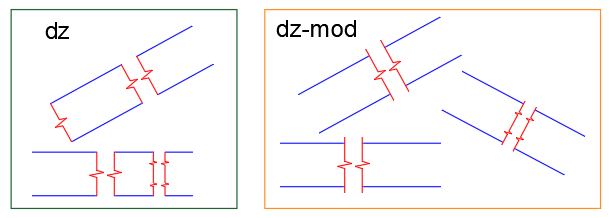
A small modification of the DZ code for convenience. The Break lines can be lengthen by the specified distance (Fixed) or proportionally (by 1/3) or None. [Fixed/Proportional/None] ;;; Lisp to draw Single or Double "Z" Break Lines ;;; © A.Henderson 2002 ;;; Modified By Charles Alan Butler 10/06/2004 ;;; To allow any angle and to trim lines that ;;; do not run through both break symbols ;;; Modified 12/02/26 ;;; The Break lines can be lengthen by the specified distance (Fixed) ;;; or proportionally (by 1/3) or None (defun c:dz-mod (/ oldlay oldotho oldosmode ztype dist ang extOpt extLen dist0 segLen e1 e2 p1 p2 p3 p4 p5 p6 p7 p8 p9 p10) ;; return vertex list by MP (defun cdrs (key lst / pair rtn) (while (setq pair (assoc key lst)) (setq rtn (cons (cdr pair) rtn) lst (cdr (member pair lst)) ) ) (reverse rtn) ) ; defun ;; set osnaps ON/OFF (defun setosnaps (value) ; value = "ON" or default to "OFF" (if value (setq value (strcase value)) ) (cond ((or (and (= value "ON") (>= (getvar "osmode") 16383)) (and (/= value "ON") (<= (getvar "osmode") 16383)) ) (setvar "osmode" (boole 6 (getvar "osmode") 16384)) ) ) ); defun ;; Start of routine ================================== ;; Save settings (setq oldlay (getvar "clayer") oldortho (getvar "orthomode") oldosmode (getvar "osmode") ) ;_ end of setq ;; I use current layer - CAB ;;(command "_.layer" "_make" "Z-Line" "_Colour" "41" "" "") (initget "S D") ;(setq ztype (getkword "\n Single or Double -^v-^v- ? (S or D) <S>")) (setq ztype (getkword "\n Single or Double -^v-^v- ? [S/D] <S>")) (setosnaps "ON") ; force on ;;=========================================== (if (and (setq p1 (getpoint "Starting point of break line : ")) (setq p6 (getpoint p1 "End point of break line : ")) ) (progn;=========================================== ;;; --- EXT --- calculate the base length/angle based on the selected points (setq dist0 (distance p1 p6)) ;;; --- EXT --- elongation mode (Fixed = 50 by default) (initget "F P N") (setq extOpt (getkword "\nExtend beyond picked points? [Fixed/Proportional/None] <Fixed>: ")) (cond ((or (not extOpt) (= extOpt "F")) (setq extLen (getdist "\nExtension length <50>: ")) (if (null extLen) (setq extLen 50.0)) ) ((= extOpt "P") ;; 1/3 of the straight section (straight section = 0.4167*dist for S, and 0.4167*(dist/2) for D) (setq segLen (* 0.4167 (if (= ztype "D") (/ dist0 2.0) dist0))) (setq extLen (/ segLen 3.0)) ) (T (setq extLen 0.0)) ) (setvar "plinewid" 0) (command "._undo" "_begin") (cond ((/= ztype "D") ; default to single (setq dist (distance p1 p6) ang (angle p1 p6) p2 (polar p1 ang (* 0.4167 dist)) p5 (polar p1 ang (* 0.5833 dist)) p3 (polar p2 (+ 1.25664 ang) (* 0.1667 dist)) p4 (polar p5 (+ 4.39824 ang) (* 0.1667 dist)) ) ;_ end of setq ;;; --- EXT --- we only lengthen the ends (the symbol remains at the base points) (setq p1 (polar p1 (+ ang pi) extLen) p6 (polar p6 ang extLen) ) (setosnaps "OFF") ; force off (command "_.pline" p1 p2 p3 p4 p5 p6 "") ; Draw the Z-Line ) ;_ end cond "S" ;;=========================================== ((= ztype "D") (setq p10 p6 dist (/ (distance p1 p6) 2.0) ang (angle p1 p6) p2 (polar p1 ang (* 0.4167 dist)) p5 (polar p1 ang (* 0.5833 dist)) p3 (polar p2 (+ 1.25664 ang) (* 0.1667 dist)) p4 (polar p5 (+ 4.39824 ang) (* 0.1667 dist)) p6 (polar p5 ang (* 0.8334 dist)) p9 (polar p6 ang (* 0.1661 dist)) p7 (polar p6 (+ 1.25664 ang) (* 0.1667 dist)) p8 (polar p9 (+ 4.39824 ang) (* 0.1667 dist)) ) ;_ end of setq ;;; --- EXT --- we extend the start and the very end (p10), we do not touch the inside (setq p1 (polar p1 (+ ang pi) extLen) p10 (polar p10 ang extLen) ) (setosnaps "OFF") ; force off (command "_.pline" p1 p2 p3 p4 p5 p6 p7 p8 p9 p10 "") ; Draw the Z-Line ) ;_ end cond ) ; end cond stmt ;; Position the second break line (setq e1 (entlast)) (command "_.pedit" e1 "_L" "_ON" "") (command "_.copy" e1 "" (getvar "lastpoint") pause) (setq e2 (entlast)) (setq plast (getvar "lastpoint")) ;; trim function (initget "Y N") (setq ans (getkword " Do you wish to trim the lines now ? [Y/N] <Y>")) (if (or (= ans "Y") (not ans)) (progn (setq lst '() dist (/ dist 140.0) ; trim distance ) ;; create trim lines (command "._offset" dist e1 plast "") (setq evl1 (cdrs 10 (entget (entlast)))) ; ent vertex list (entdel (entlast)) (command "._offset" dist e2 p1 "") (setq evl2 (cdrs 10 (entget (entlast)))) (entdel (entlast)) (setq lst (append evl1 (reverse evl2))) (setosnaps "OFF") ; force off (command "_.trim" e1 e2 "" "_F") (apply 'command lst) (command "" "") (command "_.trim" e1 e2 "" "_F") (apply 'command lst) (command "" "") ) ; progn ) ;_ endif (command "._undo" "_end") ) ; progn ) ; endif ;;================ ;; Exit sequence ;;================\ ;; Restore settings ;; I use current layer - CAB ;;(command "_.layer" "set" oldlay "") (setvar "orthomode" oldortho) (setvar "osmode" oldosmode) (princ) ) ;_ end of defun (prompt "\nDouble Break Symbol Creator loaded. Type DZ to run it." ) (princ) (setfunhelp "c:dz" "acadtools.chm" "dz")
-

Text disappears behind viewport
SLW210 replied to Samr1979's topic in AutoCAD 2D Drafting, Object Properties & Interface
I merged your 2 threads, no need to post twice, if you post in the wrong forum it can be moved, 2 threads becomes confusing. -

Copying a Value into the Clipboard without using Active-X so it can work on LT
Steven P replied to CivilTechSource's topic in AutoLISP, Visual LISP & DCL
Generally I save to the same folder as the CAD file - most of our projects however have a PDF folder... but the relative file paths to these are different depending which project manager sets up the folders... so save to the same as the CAD file is easiest and most logical really. Usually I have windows Explorer opened at that point anyway from opening the files to start with. (setq MyFilePath (getvar 'dwgprefix) ) ;; Example c:\\CADFolder\\TestFiles\\ (setq MyFileName (vl-filename-base (getvar 'dwgname)) ) ;; Example MyDrawing (setq MyFileNamePlusType (getvar 'dwgname) ) ;; Example MyDrawing.dwg (setq PDFFilePathandName (strcat MyFilePath MyFileName ".pdf") );; Example c:\\CADFolder\\TestFiles\\MyDrawing.pdf Noting the double \\ is generated automatically with these. Which might be applied to yours like this: (setq MyFilePath (getvar 'dwgprefix) ) (setq final (strcat Dwg_No "-" Dwg_Status "-" Dwg_Rev "_" Dwg_Name)) (setq PDFFilePathandName (strcat MyFilePath final ".pdf") ) As for comfortable with things, once you show them PDFs being made with 6 or 7 characters from the keyboard, command line, should win them over -
 hsec joined the community
 -
Also has some Breakline symbols here... http://www.theswamp.org/index.php?topic=37531 I seem to recall getting a similar LISP from Cadalyst years ago, but since CAB's works per OP, I am not planning to see if I can dig it up.
-

Copying a Value into the Clipboard without using Active-X so it can work on LT
CivilTechSource replied to CivilTechSource's topic in AutoLISP, Visual LISP & DCL
Hi @BIGAL I have tried the getpropertyvalue and it works in LT! Which is good news as that means the lisp can be reduced. @Saxlle that could be a solution, but the whole point is to automate it as much as possible. I had a think about it before and the most effective way for out team is to just type print me and then the drawing name gets generated and saved on the clipboard and then when they setup the plot settings they can paste the name in the dialogbox. So pausing to copy the name, will add extra steps which I am trying to reduce. @Steven P that would be the final step making sure that it is completely automated. But fearing some might not be comfortable with it yet, I just want to slowly introduce these little automations. With your suggestion, how does it work in terms of where to save the pdf file? -
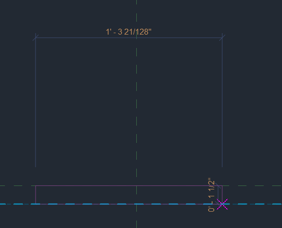
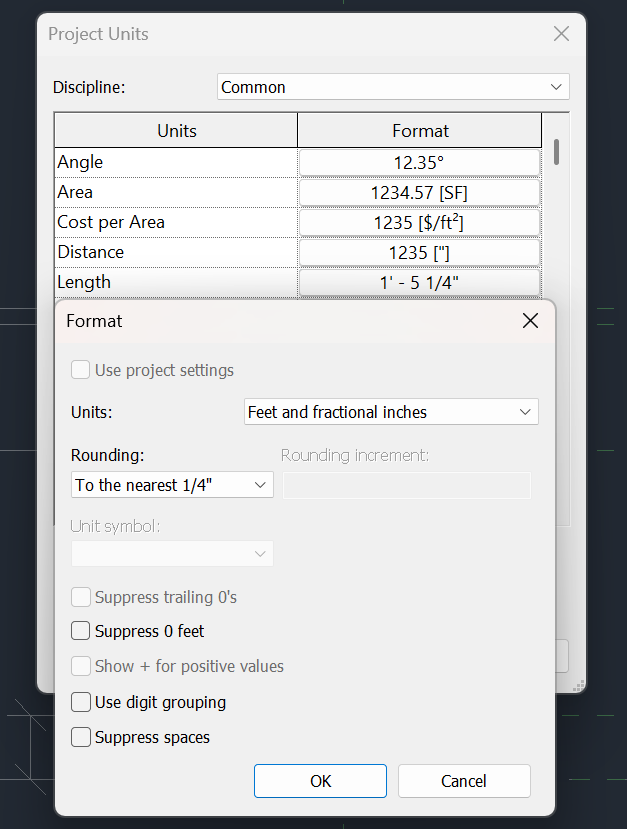
When I am making a new component and drag, the dimensions are in 128ths... My units are set to the nearest 1/4" (so I thought) Where do I set my units such that dragging constrains to the nearest 1/4"
-
SuperBoundary • The superior boundary creation tool
SLW210 commented on Debalance's file in Programs and Scripts
 Looks like the certificate expired a month ago, that's why there is a warning. They haven't been around in nearly 2 years and appears to be gone from Autodesk APP Store. There is a YouTube Channel and Facebook page, but others have been trying to contact him since December 2024 with no luck AFAIK.
 -
Penn Foster AutoCAD Applications-Construction assistance (Residential House Project)
ReMark replied to TimC's topic in Student Project Questions
Try using a scale factor of 60. That equates to an architectural scale of 1"=50". -
Penn Foster AutoCAD Applications-Construction assistance (Residential House Project)
SLW210 replied to TimC's topic in Student Project Questions
Almost every project should be on here AFAIK. Student Project Questions - AutoCAD Forums Here is the Oleson Village... Penn Foster Student Suffering with Oleson Village Map!!! - Student Project Questions - AutoCAD Forums -
OK folks, new guy here. So far in my research it sounds like Penn Foster should have their own dedicated forum. I was wondering if there was somewhere projects are posted so we can compare to be sure we've done stuff correctly? I submitted my "Oleson Housing Development" project and received a 15% because "the scale was off". Needless to say, I was less than impressed. I've sent weeks working on this project for the third semester between working overtime and sleep so I want to be sure I don't get a grade like that again. Thank you in advance for any help