All Activity
- Past hour
-
i think this is the thread with CABs code. https://www.theswamp.org/index.php?topic=10992.0
-
 Alex Brikulsky changed their profile photo
- Today
-
i cannot replicate this. When i first open TrueViewports.dwg "Layout2" is already initialized. Without initializing "Layout1" Running (sslength (ssget "_X" '((0 . "VIEWPORT") (67 . 1) (-4 . "/=") (69 . 1)))) -> i get 7 But running (length (rjp-getvports)) -> i get 6 so at least for me on this test drawing file @ronjonps code seems to work without initializing the layouts.
-
 Fahmi joined the community
-

When should you use a CAD block instead of a group?
indiancad posted a topic in AutoCAD Drawing Management & Output
In large 2D drawings, similar objects such as symbols, equipment layouts, and standard details are often repeated several times. Using blocks makes it possible to update all instances from a single definition, while groups allow objects to be selected and handled together without creating a reusable block definition. Choosing the wrong approach can make later editing and drawing maintenance more difficult. When managing repeated geometry in production drawings, do you prefer blocks or groups? What factors influence your choice? -
Even a well-prepared CAD drawing can produce unexpected results when converted into a PDF or printed. Different settings and drafting practices can affect the final output. In your experience, what causes the most plotting problems?
-
A drawing may look properly organized with different lineweights assigned to layers, but the final PDF or printed output can look completely different. Some lines appear too thick, while others become difficult to distinguish. One possible cause is a mismatch between layer lineweight settings and CTB/STB plot style configurations. The PLOT settings and selected plot style table can override the appearance you expect. When your plotted output doesn't match the drawing display, what do you check first: layer properties, CTB/STB settings, or plot configuration? Have you encountered any less obvious causes?
-
How do you verify the accuracy of a 3D model before creating production drawings?
indiancad replied to indiancad's topic in AutoCAD 3D Modelling & Rendering
I agree. A 3D model can help verify the geometry, but a fully dimensioned 2D drawing is still important for manufacturing. Sections and profiles also make it easier to check critical areas, especially on complex parts. I think the right approach depends on how the part will be manufactured and what information the production team needs. -

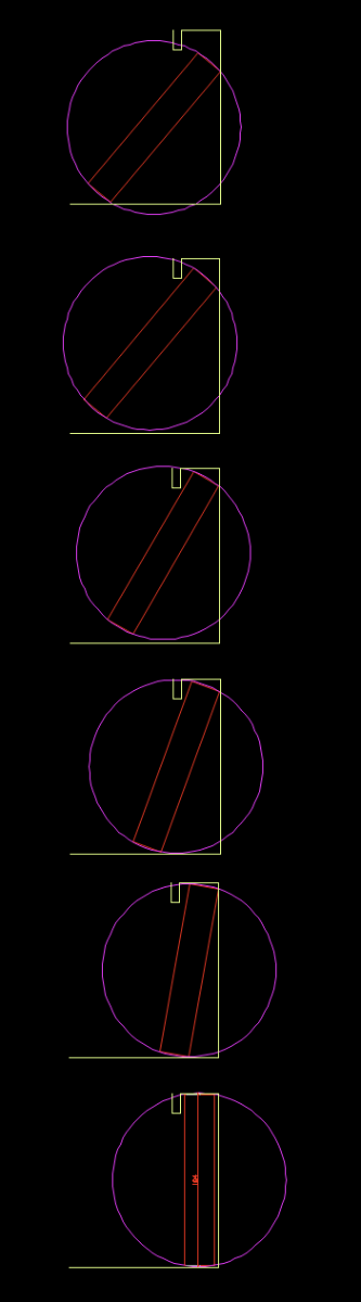
Fitting without collision
Discus84 posted a topic in AutoCAD 2D Drafting, Object Properties & Interface
HI, The yellow line is wall, red is a box. I would like to know if the box fits by turning and sliding into opening. I put it into a circle as a bounding box and manually moved it around to check. There must be a more elegant way of doing this and mabe a way to calculate the max height of such box knowing its width and the wall depth with header height. Thanks!
- Yesterday
-
FYI, Your code works fine in your sample dwg because as you loop through each layout the space is already set in pspace. But the code fails when it encounters a layout with a vport set in mspace. The following revised loop segment code accommodates for this: (vl-catch-all-apply '(lambda () (foreach lay (layoutlist) (setvar "CTAB" lay) ; (setvar "CVPORT" 1) ; this will error out if in mspace (setq cvport (getvar "cvport")) ; save current psace vport # (if (> 1 cvport) ; chk if in mspace (progn ; then (vl-cmdf "_.Pspace" "_.ZOOM" "_E" "_.Mspace") ; goto pspace then zoom extent and return to mspace (setvar "cvport" cvport) ; return to mspace of original vport # ) (vl-cmdf "_.ZOOM" "_E") ; else just zoom extent in pspace ) ; if ) ; foreach ) ; lambda
-
Like @SLW210 I had a move the title block in layouts to 0,0 and then zoom extents, had one user that would move the title block as it was the way he liked to draft. We had auto plot layouts so was part of our company standard to have title at 0,0.
-
@PGia there are other ways to sort lists other than inbuilt Vl-sort. You can use a Lisp version of Bubble sort and other sort algorithms. I sort up to 5 items deep in a list and as far as I can tell none are lost. Yes have seen that with some lists using VL-sort. So you can sort on say X & Y. ; sorts on 1st two items (vl-sort lst '(lambda (a b) (cond ((< (car a) (car b))) ((= (car a) (car b)) (< (cadr a) (cadr b))) ) ) )
-
@DavidP @mhupp as they say...there's more than one way to skin a cat... either with 67 or 410 or go crazy and do both 67 & 410...but the result is the same: vports from Model are filtered out
-
sure : (alert "Press ok to start your 30hr day") anything else I can do for you?
-
@Danielm103 Interesting. I didn't know about those functions or that a parallel namespace existed. I'll look into that. Maybe it will minimize the drawbacks of using dynamic variables. @BIGAL Suppose we're dealing with elements that are scattered over a large area and you need to sort only a part of them and get a list. It might seem that the vl-sort function could be useful for this; however, it has a drawback: sometimes it deletes repeated elements from the list based on the filters. So I'm trying to do it without using vl-sort. Note: There are some objects that match exactly in location with others. @mhupp: Dictionary? What dictionary?
-
 Dossierz joined the community
- Last week
-
AutoCAD session, you need to use vl-bb-set vl-bb-ref right?
-
Dimensions look correct, but lose their connection to geometry
indiancad posted a topic in AutoCAD Drawing Management & Output
In complex 2D drawings, dimensions can sometimes become disassociated after geometry is moved, copied, or modified. They may still display the correct measurement, but no longer update when the object changes. AutoCAD's DIMREASSOCIATE command can reconnect dimensions to the intended geometry. How do you handle disassociated dimensions in large drawings? Do you use DIMREASSOCIATE regularly, or do you prefer to recreate dimensions when their references are lost? -
I get that @PGia but it almost be harder to recall the correct random variable. associated list might not be what you need with the large data set your working with. as assoc looks at all 20000 records every time. look into Dictionary before going the other route. alot faster searching because you can only have unique keys tho that might be a deal breaker for you.
-
There may be ways to speed up using a list of 20,000 points, the first is if your points are numbered then make the list that way you have to but pt number 0 as 1st item then a (nth x lst) is a simple task and does not need the (- x 1). Re find a point depending how the list is made there is a way of quickly finding the point based on a sorted list a 10,000 list takes 13 tries to find the correct answer, it uses a 1/2 algorithm, look at 5000 item is it before or after look at say 2500 is it before or after so very fast. Can you explain what it is your doing and maybe some people here can provide faster code. I know something I did took 34 minutes 1st go, it now takes 2 minutes including user input.
-
@mhupp: in principle, my goal is to make a comparison between processing speed when the information to be looked up is stored in a very large list versus when it is stored in variables. I suppose that, as Lee or Pkenewell say, it is risky. But I think that if atoms-family allows complete control of AutoCAD's symbol table, it is worth trying to test this coding method.
-
Thank you very much, @pkenewell I will try to make use of your code in my experiments. However, I'm not sure whether I should consider my question answered: can AutoCAD's internal symbol table really be controlled from atoms-family? Or is it possible that any symbol created during an AutoCAD session survives for as long as the session lasts, even if its value is nil? I apologize if my question seems awkward or absurd, but I would really like someone to give me a clear answer about this.
-

Selecting Folders (AutoCAD LT 2024)
Steven P replied to SLW210's topic in AutoLISP, Visual LISP & DCL
yes, good idea. -
I Agree with Lee I'm interested in what your actually doing. take this for example. different approaches lisps that have a large range of run times. all basically doing the same thing. mine still took over a min to run, but ronjonp came in with 4.07 sec. theirs built an main list processed that list into smaller lists. once processed removed the items from each lists. (speeds up search)
-
Here is my latest zoom .9x in all layouts. I hadn't noticed the OP posted a .dwg, so i ran my Viewport Border into Model code on it. Is the result you wanted? ====================================== AutoVPBrdr REPORT ====================================== True layout viewports: 4 Viewport layer assignments: 4 Layer assignment failures: 0 Modelspace borders created: 3 Viewports skipped: 1 -------------------------------------- Layer: Viewport Color: 45 Plot: OFF ====================================== ZE_Z9XP_1.1.lsp
-
@PGia While it's very possible to create variables on the fly. I agree with Lee that it should not be a method to use, especially in the way you are wanting to use it. That being said, I wrote the following many years ago, but hardly have ever used it for anything. It accepts an assoc. list of strings representing variables and the corresponding values, then creates a variable for each with the value. The core of it is very simple (set (read "StrVar") value) ;|============================================================================== Function Name: (pjk-dynsetvar) Arguments: assoclst = List of cons; an assoc list on the format: (list (cons "<var name1>" <value1>) ... (cons "<Var namN>" <valueN>)) Usage: (pjk-dynsetvar <Assoc. List>) Ex: (pjk-dynsetvar (list (cons "Cenpt" (list 1.0 1.0 0.0)) (cons "Radius" 0.25))) Returns: The results of the read list. You can verify the variables with the ! prefix: Command line Example: Command: (pjk-dynsetvar (list (cons "Cenpt" (list 1.0 1.0 0.0)) (cons "Radius" 0.25))) ((1.0 1.0 0.0) 0.25) Command: !Cenpt (1.0 1.0 0.0) Command: !Radius 0.25 Description: This function dynamically sets AutoLISP variables based on an association list of strings and values. The string keys represent the names of the variables that the values will be assigned to. ================================================================================|; (defun pjk-DynSetVar (assoclst) (mapcar (function (lambda (x)(set (read (car x)) (cdr x)))) assoclst) ) ;; End Function (pjk-dynsetvar)
-
It seems it's not placing CENTERMARKS in Mechanical, I haven't tested other verticals from the toolset, it does use my fallback CrossHairs, though. I may not bother getting CENTERMARK to work in verticals unless someone else is interested, I would use the LISP in AutoCAD anyway, but I will do some testing on Mechanical/Architectural drawings in AutoCAD when I have time. Speaking of time, does anyone have a LISP or something that can give me a 30+ hour day, maybe @rlx I'll try to check this latest version in AutoCAD 2000i this weekend.
-

How do you verify the accuracy of a 3D model before creating production drawings?
SLW210 replied to indiancad's topic in AutoCAD 3D Modelling & Rendering
For most parts to be manufactured, fully dimensioning the 2D drawing would show any errors, I have never worked anywhere that manufactured from the 3D model, always needed a 2D drawing fully dimensioned. Though, I suppose for arguments sake, possibly could just make a model, create the 2D profiles and send them to a waterjet/plasma cutter, in that instance I would dimension relevant places/points and remove the dimensions before sending the profile, though in reality, I always create a fully dimensioned 2D anyway and I have sent the waterjet programmer the dimensioned profile if requested, it can be made a non-path object or deleted there. I rarely need specific dimensions on my 3D prints, though I draw them to a specific size usually, the ones that need mating parts I do same as you, but then again, creating 2D profiles, sections etc. can be of great help.