All Activity
- Past hour
-

Drawing a house with just 10-key input.
Steven P replied to Ataim's topic in AutoLISP, Visual LISP & DCL
Try this as a first pass, see if I have the idea right: Not quite as described and only draws lines as it is, rather than Polylines, but it being a Sunday and the CAD should be off it will do for a start, or if it inspires anyone tonight. To consider later: Fixing the loop - as it is just escape out of the LISP to end or join last point to start point. Join the lines together as Polylines (See Lee Mac PLJoin?) (defun c:testthis ( / Pta Ptb Pt1 Pt2 MyLine MyDistance MyAngle ed RefLine RefAngle ) (defun LM:roundm ( n m ) ;; Lee Mac (* m (fix ((if (minusp n) - +) (/ n (float m)) 0.5))) ) (command "line" pause pause "") (setq RefLine (entlast)) (setq Pta (setq Pt1 (cdr (assoc 10 (entget RefLine)))) ) (setq Ptb (setq Pt2 (cdr (assoc 11 (entget RefLine)))) ) (setq RefAngle (angle Pt1 Pt2) ) (setq endloop "No") (while (and (= endloop "No") (= (command "line" Pt2 pause "") nil) ) ; end and (setq ed (entget (entlast))) (setq Pt1 (cdr (assoc 10 ed))) (setq Pt2 (cdr (assoc 11 ed))) (if (equal Pt2 Pta) (progn (princ "Closed Polyline") (setq Endloop "Yes") ) ; end progn (progn (setq MyDistance (distance Pt1 Pt2)) (setq MyAngle (LM:roundm (- (angle Pt1 Pt2)(angle Pta Ptb)) (/ pi 4) )) ; pi/4: 45 degree angles (setq Pt2 (polar Pt1 (+ MyAngle (angle Pta Ptb)) MyDistance)) (setq ed (subst (cons 11 Pt2) (assoc 11 ed) ed )) (entmod ed) ) ; end progn ) ; end if ) ; end loop (princ) ) ; end defun -

Drawing a house with just 10-key input.
robierzo replied to Ataim's topic in AutoLISP, Visual LISP & DCL
I use this Lee Mac lisp. I find it very useful. It's not exactly what you're asking for, but it might be a big help. https://www.lee-mac.com/3pointrectangle.html - Today
-

Drawing a house with just 10-key input.
mhupp replied to Ataim's topic in AutoLISP, Visual LISP & DCL
look into dynamic blocks -
 BOLAAWO joined the community
 -
 osi joined the community
 -
 Nshimiyimana Emmanuel joined the community
 -
 justanothercadguy joined the community
 - Yesterday
-

Node of Arc Length Dimension
tombu replied to dickeychan's topic in AutoCAD 2D Drafting, Object Properties & Interface
I've always set Plot layout for plotting for that reason and set Plot to Center as well so if a plotter with different margins was used it would still plot exactly the same way. -
No idea, it was up and running a day or two before. No explanation other than "If you have any questions, please contact AUGI."
-

Drawing a house with just 10-key input.
BIGAL replied to Ataim's topic in AutoLISP, Visual LISP & DCL
Many years ago "Civilcad" software had that function, draw a shape and click on boundaries you could do things like set a side and slide along that side with updating offset to other sides as one option. So understand what you want but no solution, sorry. Not sure if it ended up in current software "Magnet". Note in the image the offset line to the angled line., it will always be the closest corner and changes automatically depending on the shape. Welcome to Cadtutor. Post a sample dwg with some examples of what your looking for, a before and after is best.
-
 wilmaknight81 joined the community
 -
Drawing a house with just 10-key input.
Steven P replied to Ataim's topic in AutoLISP, Visual LISP & DCL
Do you remember what the command was to run the LISP - you never know, someone might have a copy or a link to it -
Really? Was an explanation offered as to why?
-
The AUGI Forums are Now Archived We have archived the AUGI Forums by making them read-only for reference purposes. No new topics or comments will be allowed going forward from March 2026. If you have any questions, please contact AUGI. Just letting you know there may be a lot more new traffic here. Unfortunately no way to let any of their users know. https://forums.augi.com/search.php?searchid=3102365
-

Drawing a house with just 10-key input.
SLW210 replied to Ataim's topic in AutoLISP, Visual LISP & DCL
I moved your thread to the AutoLISP, Visual LISP & DCL Forum. -
 Panos66 joined the community
 -
 Amirkat joined the community
 - Last week
-
 jmccarthy76 joined the community
 -
 Henma joined the community
 -
 Ataim joined the community
 -
I'm a land surveyor. Years ago I worked at a company that had a script or lisp to draw a house. Basically you started a polyline and then drug the cursor the direction you wanted to go. Then you would put in the distance. Then you simply type the next distance and would draw that distance 90° to the right of the last line. Or if you put a - in front of the distance it would draw 90° to the left of the last line. Or you could add / or \ to draw 45° to the last line. You would continue until you are done. I would be willing to pay $$$$ if someone could write this for me.
-
 Perhaps it will suit you. Polyline Dimension by marko_ribar (defun c:pdim ( / ListClockwise-p ch plSet pLlst vLst oldOsn cAng cDis cPt ) ;;; Polyline Dimension by marko_ribar ;;;https://www.cadtutor.net/forum/topic/54351-automatic-distance-between-polygon-vertices/#comment-451128 ;;; posted https://forum.dwg.ru/forumdisplay.php?f=13 (vl-load-com) (defun ListClockwise-p ( lst / z vlst ) (vl-catch-all-apply 'minusp (list (if (not (equal 0.0 (setq z (apply '+ (mapcar (function (lambda (u v) (- (* (car u) (cadr v)) (* (car v) (cadr u))) ) ) (setq vlst (mapcar (function (lambda (a b) (mapcar '- b a)) ) (mapcar (function (lambda (x) (car lst))) lst) (cdr (reverse (cons (car lst) (reverse lst)))) ) ) (cdr (reverse (cons (car vlst) (reverse vlst)))) ) ) ) 1e-6 ) ) z (progn (prompt "\n\nChecked vectors are colinear - unable to determine clockwise-p of list") nil ) ) ) ) ) (initget 1 "Outside Inside") (setq ch (getkword "\nChoose on which side to put dimensions [Outside/Inside] : ")) (princ "\n<<< Select LwPolyline(s) for dimensioning >>> ") (if (setq plSet (ssget '((0 . "LWPOLYLINE")))) (progn (setq pLlst (vl-remove-if 'listp (mapcar 'cadr(ssnamex plSet))) oldOsn (getvar "OSMODE") ); end setq (setvar "OSMODE" 0) (setvar "CMDECHO" 0) (command "_.undo" "_be") (foreach pl pLlst (setq vLst (mapcar '(lambda( x ) (trans x 0 1)) (mapcar 'cdr (vl-remove-if-not '(lambda( x ) (= 10 (car x))) (entget pl) ) ) ) ); end setq (if (equal (logand (cdr (assoc 70 (entget pl))) 1) 1) (setq vLst (append vLst (list (car vLst)))) ); end if (if (not (ListClockwise-p vLst)) (setq vLst (reverse vLst))) (while (< 1 (length vLst)) (setq cAng (angle (car vLst) (cadr vLst)) cDis (/ (distance (car vLst) (cadr vLst)) 2.0) ) ;_ (if (>= (caar vLst) (caadr vLst)) ;_ (setq cAng (- cAng pi)) ;_ ); end if (if (eq ch "Inside") (setq cPt (polar (polar (car vLst) cAng cDis) (- cAng (* 0.5 pi)) (* 2.5 (getvar "DIMTXT")))); end setq (setq cPt (polar (polar (car vLst) cAng cDis) (+ cAng (* 0.5 pi)) (* 2.5 (getvar "DIMTXT")))); end setq ); end if (command "_.dimaligned" (car vLst) (cadr vLst) cPt) (setq vLst (cdr vLst)) ); end while ); end foreach (command "_.undo" "_e") (setvar "OSMODE" oldOsn) (setvar "CMDECHO" 1) ); end progn ); end if (princ) )
 -
Text disappears behind viewport
SLW210 replied to Samr1979's topic in AutoCAD 3D Modelling & Rendering
Once I made your MText large enough it was very visible. Try placing the MText in PaperSpace. -
Another way to approach this ";; Loop through vertices" is to get all the vertices and simply use those XY values of the corresponding two points in a repeat. You can check the readabilty of the answer by looking at the angle of the two points, so place answer above or below. There are plenty of label plines out there do a google, "Kent Cooper" has some good ones. may be faster than debugging what you have. setq plent (entsel "\nPick pline")) (if plent (setq co-ord (mapcar 'cdr (vl-remove-if-not '(lambda (x) (= (car x) 10)) (entget (car plent)))))) (princ co-ord)
-
Text disappears behind viewport
BIGAL replied to Samr1979's topic in AutoCAD 3D Modelling & Rendering
This question has been asked before. Do a google or search here. I remember posting something. -
This lisp puts dimensions on a pline, how can I have it put the dimensions above the pline? Also it doesn't put a dimension on the last line.
SLW210 replied to Mitch Ellis's topic in AutoLISP, Visual LISP & DCL
In the future please place your code in Code Tags. (<> in the editor toolbar) -

Civil Drafting with AutoCAD Project-Civil Drafting with AutoCAD Project
ReMark replied to nelsonm's topic in Student Project Questions
Ok. Guess they changed it. -
 (defun c:PLD (/ ent obj i p1 p2) (vl-load-com) (if (setq ent (car (entsel "\nSelect Polyline to Dimension: "))) (progn (setq obj (vlax-ename->vla-object ent)) (if (= (vla-get-ObjectName obj) "AcDbPolyline") (progn (setvar "cmdecho" 0) (command "._undo" "_begin") (setq i 0) ;; Loop through vertices (repeat (fix (- (vlax-curve-getEndParam obj) 1)) (setq p1 (vlax-curve-getPointAtParam obj i) p2 (vlax-curve-getPointAtParam obj (1+ i))) ;; Create aligned dimension (command "_.dimaligned" "_none" p1 "_none" p2 "_none" (polar p1 (+ (angle p1 p2) (/ pi 2)) 1.0)) (setq i (1+ i)) ) (command "._undo" "_end") (setvar "cmdecho" 1) ) (princ "\nSelected object is not a LightWeight Polyline.") ) ) ) (princ) ) (princ "\nType 'DimPlineSegments' to run.")
 -
When I have a viewport that show a 3D object and have to change the visual style to anything but 2d wire frame, any text I put inside the viewport box disappears. Anyone know how to fix this? TEXT_MISSING.dwg
-
Problem plotting with ACAD2024
Steven P replied to diogenes666's topic in AutoLISP, Visual LISP & DCL
Do you plot using the AutoCAD "plot" function? Or a LISP - the OP had a LISP to plot with (?) which might have been an issue and is this a new thing that is happening? -

Civil Drafting with AutoCAD Project-Civil Drafting with AutoCAD Project
nelsonm replied to nelsonm's topic in Student Project Questions
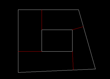
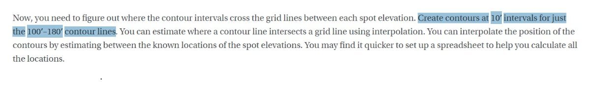
Oh its ok, in one part of the guide, it says the following: "Create contours at 10′ intervals for just the 100′–180′ contour lines" So I thought I would only work on the points ranging from 100 to 180. Could I be wrong? Thank you very much for the guidance. I already know your instructions, and this is what I did. Could you tell me if this is correct?
-

Dynamic Blocks corrupted after a while of usage in ZWCAD
cad_tutee replied to cad_tutee's topic in AutoCAD Drawing Management & Output
Hi, thanks for the offer. I am doing exactly that with my blocks. I directly data extract to an excel file and that I find to be the most convenient until my blocks got corrupted after which the blocks stopped showing up in the data extraction menu box. I am familiar with data extraction of the blocks. The root problem is ZWCAD does not allow data extraction of the contents of mtext or does not data extract mleaders at all, which is why I had to create the dynamic block. I really want to know why the dynamic blocks get corrupted and if there's a way to return it back to the original definition of the block. I found out recently that a fairly simple dynamic block I made within ZWCAD got corrupted too. I am reattaching the Issue.dwg with some more information. . -
OOPS only restores objects that were erased by the last ERASE command.
-
Just my $0.05 there was another post about doing breaklines maybe at Forums/autodesk/lisp. One answer provided had multiple break styles that looked very useful. I will spend a couple of minutes and see if I can find the link.
-
Beug Autocad dans la fenêtre de présentation
BIGAL replied to Pepsifoldu69's topic in AutoCAD Bugs, Error Messages & Quirks
Welcome to Cadtutor. !st step run AUDIT and look for errors. 2nd ? In this problem case I use Notepad++ a text editor its free, it has a function "Compare" so you can compare two files, in the case of CAD you look at all the variable settings. You use a Log file, the command LOGFILEOn starts it LOGFILEOFF stops it, you run it on two different PC's. The log file is located in your temp directory under Options Files Temporary directory. 3rd you may want to audit the Xrefs. If your happy can you post the dwg here so we can try to find problem.