All Activity
- Today
-

Entering survey data for Penn Foster Olsen Village Project
ReMark replied to Cryptic's topic in Student Project Questions
This is addressed in the thread I told you about yesterday via private message. Please take a look at the aforementioned thread as I suggested. Thank you. -
 mattmurdok joined the community
 -
Drawing the line would also pick up 4 lines across the block. would maybe have to do a fence ssget. and if block draw a bounding box to pick up lines but even then could be inaccurate if not a square.
-
 cillianjohn joined the community
 -
That may be part of it, but I think some of it has to do with the answers to many inquiries is available without a login, and yes AI sometimes gives that in the answer to a search. Any search I do with the search engine (DuckDuckGo) gives an AI response at the top, or supposedly a summary of the results, the AI results can be inaccurate to say the least. I do see some posting on this and other forums for correct answers after the AI sends them down the wrong road. I seldom login to AUGI and Autodesk Forums, Autodesk rearranges their forum so much many links, some not even very old, go to a dead end now.
-
 As I mentioned already, you need to start a new thread in the AutoLISP, Visual LISP & DCL Forum.
 -
 Thank you for the plugin it worked well
 -
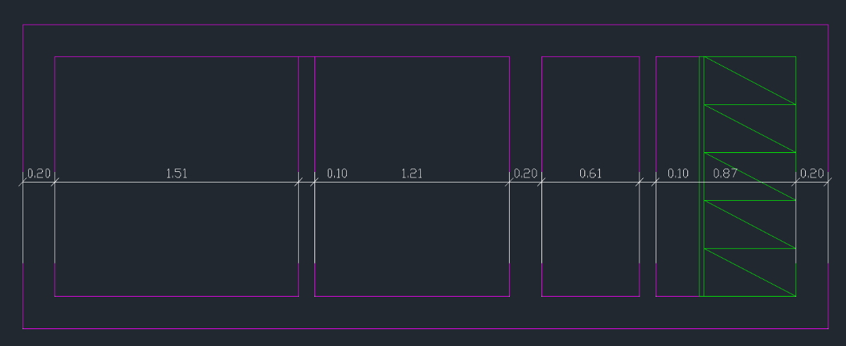
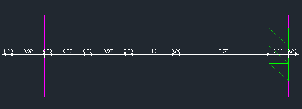
Hi BIGAL, I have try QDIM but working as The QDIM don't dimension the block (look the image) I want to draw a line by specifying two points, to indicate where dimensions should be placed. This line should only appear on the layers named WALLS-2D and CLOSETS-2D. The WALLS-2D layer contains both lines and polylines, while the CLOSETS-2D layer contains blocks. Thanks

-

TotalBoundary • Outline creation tool
Ankit Pandit commented on Debalance's file in Programs and Scripts
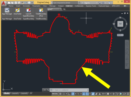
Hello, Anyone knows any tool or CAD plugin that extracts 2D boundary for drawings? i tried the total boundary but my trail period is over and I am not able to purchase the total boundary please help me find a tool -
 Tawan joined the community
 -
 CY CHOI joined the community
 - Yesterday
-
 Jegan joined the community
 -
Yes I have something done like 40 years ago, but did you try QDIM is that in ZWCAD ?
-
I am searching for a lisp code to recognizes and dimensions LINE or ARC objects located in the Wall-2D layers and blocks in the CLOSETS-2D layer. like the image The dimension layer is DIM The idea is to pick 2 points like a line and automatic insert the dmensions. I use ZWCAD. Thanks
-

Entering survey data for Penn Foster Olsen Village Project
Cryptic posted a topic in Student Project Questions
I am having issues with the beginning steps of the final project. I have been prompted to enter survey data, but every time i press enter to place the line down, it will just put a line down at where my cursor is. -
This is sad news and a little concerning that no explanation is being given. On the face of it, it looks like a complete disregard for the community - I hope that's not true. What is true is that community engagement on forums like this has declined in recent years. Some of that decline is a result of AI. I know that this site has been scraped by LLM bots and, as a result, people seeking answers don't need to visit the site if an AI agent can provide the answer. Just to let you know, I have no intention of closing or suspending this forum any time soon.
- Last week
-
 atakan joined the community
 -

Understanding 'Getenv Variable call denied'?
mhupp replied to ScottMC's topic in AutoLISP, Visual LISP & DCL
Tired to squeeze three lines into one from lee's code converted it back. -
Understanding 'Getenv Variable call denied'?
ScottMC replied to ScottMC's topic in AutoLISP, Visual LISP & DCL
Did crash upon: 'repeat.. changed my working 'C2 with the while cmdecho. Thanks -- Actually nice but the osnaps don't work with grrrr, the crash was from 'ctan:res var being unfilled (40..) true, an interesting alternate. Thanks mhupp. -

Add to the code the ability to create layouts for non-standard formats
Nikon replied to Nikon's topic in AutoLISP, Visual LISP & DCL
Thanks, I'll try it. There is another option, but it does not work for all formats. ;; A3x3 (420x891) ((and (<= SideS 425) (<= SideL 896)) (vla-put-CanonicalMediaName Layout "UserDefinedMetric (891.00 x 420.00мм)")) -

Add to the code the ability to create layouts for non-standard formats
pkenewell replied to Nikon's topic in AutoLISP, Visual LISP & DCL
@Nikon The "COND" statement will stop as soon as it meets the criteria for the square area range, so if something else meets the that area range before getting to your desired state, it will never get there. You will have to do a different comparison that is unique to the criteria. Maybe to change the criteria for the conditional statement to comparing the Length and width specifically, rather than with the area, or a combination of the area and the width, or something else, like a unique layer or color. Maybe something like this instead (you can alter to suit the fudge factor for the viewport height and width): (cond ((and (> 290.0 ViewPortHeight 300.0) (> 600.0 ViewPortWidth 650.0));; Compare the width and height directly! (vla-put-ConfigName Layout "DWG To PDF.pc3") (vla-put-CanonicalMediaName Layout "UserDefinedMetric (297.00 x 630.00мм)") ) ((and (> 290.0 ViewPortHeight 300.0) (> 835.0 ViewPortWidth 845.0)) (vla-put-ConfigName Layout "DWG To PDF.pc3") (vla-put-CanonicalMediaName Layout "UserDefinedMetric (297.00 x 841.0мм)") ) ... ;; Repeat for all desired sizes ) NOTE: You would also have to do both a landscape version and a Portrait version if you need both. Perhaps a bit more sophisticated comparison: (cond ((or (and (> 290.0 ViewPortHeight 300.0) (> 600.0 ViewPortWidth 650.0)) (and (> 290.0 ViewPortWidth 300.0) (> 600.0 ViewPortHeight 650.0)) ) (vla-put-ConfigName Layout "DWG To PDF.pc3") (vla-put-CanonicalMediaName Layout "UserDefinedMetric (297.00 x 630.00мм)") ) ((or (and (> 290.0 ViewPortHeight 300.0) (> 835.0 ViewPortWidth 845.0)) (and (> 290.0 ViewPortWidth 300.0) (> 835.0 ViewPortHeight 845.0)) ) (vla-put-ConfigName Layout "DWG To PDF.pc3") (vla-put-CanonicalMediaName Layout "UserDefinedMetric (297.00 x 841.0мм)") ) ... ; Repeat for all desired sizes (T (vla-put-ConfigName Layout "None")) ; Default to No plotter for non-standard sizes ) NOTE: I can't test this directly without a "real world" sample drawing to compare, along with your pc3 file, so I'm trying to give you the knowledge to do it yourself, which is preferrable anyway. -
Hi, you did a fantastic job. The few options is realy good, and handy to use. I have only 1 question left - can that tool not create a clone of polyline, but edit current? To transform polyline with all parameters and e.t.c. If you will be doing that, its nessesary obly for lw_orth_2 (2nd version) it works better for cases i have faced. Does it even possible to transform line like it doing it not with clone? Thanks you very much already!!!
-
Help for change element property lisp!
mhupp replied to norad's topic in AutoLISP, Visual LISP & DCL
(setq ss (ssget "X" '((-4 . "<OR") (62 . 40) (62 . 33) (62 . 25) (62 . 179) (-4 . "OR>")))) https://www.lee-mac.com/ssget.html#logical -
Understanding 'Getenv Variable call denied'?
mhupp replied to ScottMC's topic in AutoLISP, Visual LISP & DCL
just FYI for @ScottMC That while loop is running 1000's times a sec and is intended to only pause waiting for user input to be completed. Can be simplified to this. (while (> (getvar 'CMDACTIVE) 0) (Command "\\") ) Another option would be to use grread and grdraw to show a visualization of a circle but not actually add it to the drawing (in red). Tho I found out it can only draws lines and you need to trick it to make segmented circles. will post something later tonight. -- Edit This doesn't have any command so doesn't need above code or to toggle CMDECHO. ;;----------------------------------------------------------------------;; ;; 2 Point Circle ;; grcircle function from https://lee-mac.com/circletangents.html (defun c:C2 (/ *error* cr P1 P2 P3 rad ev oe os doc) (defun *error* (msg) (setvar 'OSMODE os) (vla-endundomark doc) (princ (strcat "\n" msg)) ) (defun grcircle (cen rad / ang) (setq ang 0.0) (repeat ctan:res (grdraw (polar P3 ang rad) (polar P3 (setq ang (+ ang ctan:inc)) rad) 1) ) ) (setq doc (vla-get-ActiveDocument (vlax-get-acad-object))) (vla-startundomark doc) (setq ctan:res 40 ;; arc resolution (int > 0) ctan:2pi (+ pi pi) ctan:inc (/ ctan:2pi ctan:res) ) (setq os (getvar 'OSMODE)) (while (and (setvar 'OSMODE (boole 7 os 512)) (setq P1 (getpoint "\nSpecify 1st Point of 2P.Circle: ")) ) (setvar 'osmode os) (prompt "\nSpecify 2nd Point: ") (while (progn (setq ev (grread t 13 0)) (= (car ev) 5) ) (redraw) (setq P2 (cadr ev)) (setq rad (/ (distance P1 P2) 2.0)) (setq P3 (Polar P1 (angle P1 P2) rad)) (grcircle P3 rad) ) (if (= (car ev) 3) (progn (setq P2 (cadr ev)) (setq rad (/ (distance P1 P2) 2.0)) (setq P3 (polar P1 (angle P1 P2) rad)) (setq cr rad) (redraw) (princ (strcat "\n Coordinates: " (setq C2:pp (strcat (rtos (car P3) 2 4) "," (rtos (cadr P3) 2 4) "," (rtos (caddr P3) 2 4))) "\n Diameter: " (rtos (* cr 2) 2 4) " | Radius: " (rtos cr 2 4))) (entmakex (list '(0 . "POINT") (cons 10 P3))) (entmakex (list '(0 . "POINT") (cons 10 P2))) (entmakex (list '(0 . "CIRCLE") (cons 10 P3) (cons 40 cr) (cons 8 (getvar "CLAYER")))) ) ) ) (setvar 'cmdecho 1) (vla-endundomark doc) (princ) ) -

How to copy an object to a specified distance
SLW210 replied to sinergy2020's topic in AutoCAD Beginners' Area
I use polar tracking and osnaps in AutoCAD. Looks like nanoCAD has similar... Precision tools. Object Snap tracking mode. Download CAD software -
 аваз joined the community
 -

How to copy an object to a specified distance
nod684 replied to sinergy2020's topic in AutoCAD Beginners' Area
take a look at this : https://help.autodesk.com/view/ACD/2025/ENU/?guid=GUID-DD9B3216-A533-4D47-95D8-7585F738FD75 -
Understanding 'Getenv Variable call denied'?
ScottMC replied to ScottMC's topic in AutoLISP, Visual LISP & DCL
Thanks PK for finding that. Something I've never found or got direct connection to error but now will have that as an understood rule. Will certainly look for that in my troubleshooting. -

How to copy an object to a specified distance
sinergy2020 replied to sinergy2020's topic in AutoCAD Beginners' Area
Not sure I totally understand this last .....is there a listing of osmodes somewhere? When I type osmode I get (by default) 549 ... what does it mean??? And, can I write lisp code in nanocad? -
Add to the code the ability to create layouts for non-standard formats
Nikon replied to Nikon's topic in AutoLISP, Visual LISP & DCL
Non-standard formats are often required for drawings. -

Add to the code the ability to create layouts for non-standard formats
BIGAL replied to Nikon's topic in AutoLISP, Visual LISP & DCL
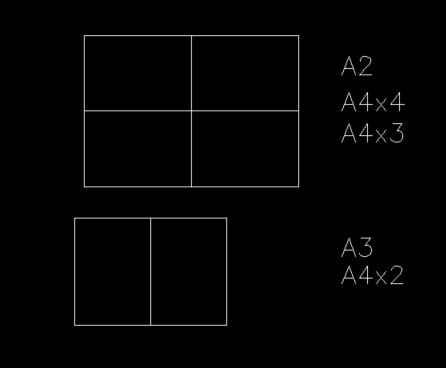
I don't understand why your using non standard size sheets ? A2 can be shown as 4 A4's same with 3 to be used but 4th blank. A A4x2 is a A3, the internal linework would be on a non plot layer. You could have 4 viewports shown.
-
How to copy an object to a specified distance
BIGAL replied to sinergy2020's topic in AutoCAD Beginners' Area
Like @CyberAngel if you set your osnap to what you want then type "Osmode" a number will appear that is current osnaps settings. Ok part two in say chx you can add this code. Note 1 is End. 0 is off. Normal drafting for me is 47. Try it (setvar 'osmode 47) then type osnap. For say a circle use 4. put at start (setq oldsnap (getvar 'osmode)) (setvar 'osmode 1) .... code put at end (setvar 'osmode oldsnap)