All Activity
- Today
-
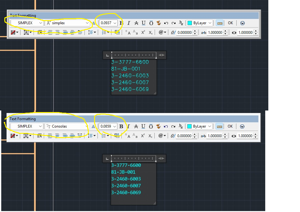
I call up an existing block of MTEXT. The style and font are both simplex. When I paste new text from a notepad file the editor changes the size and font. This is getting to be a big headache. Does anyone know how to fix this?

-
 BigDawg joined the community
 -
I was having an issue editing an alignment within 2026. I did not set up the file, or the alignment. I was trying to update the stationing but everything was locked/greyed out. I opened Geometry Editor, and unlocked the Parameter Constraints, no luck. I closed CAD, and even restarted my computer, still no luck. After selecting the alignment, it appeared to be data referenced into the file, when looking within my toolspace at data shortcuts, I did not see any such reference. With the alignment selected, I then selected Promote Data Reference under Modify within the menu, lo and behold, the alignment was editable! Maybe this is the case for you, maybe its not. Good luck!
-
https://www.zwsoft.com/support/zwcad-base-faq/517
-
Avoiding Copy and Paste to secure clipboard data progress!
ScottMC replied to ScottMC's topic in AutoLISP, Visual LISP & DCL
Suggestions received, posted and updated. As with the coords, the point is a reference entity. Thanks (defun c:4x (/ *error* pt1 pt2 ss ) (princ (strcat "\n 45"(chr 186)"/135"(chr 186)" 3D.XLines <!pp>")) ;; ai: https://www.google.com/search?q=saving+2+lines+selection%2C+autolisp&client=firefox-b-1-e&hs=AnK&sca_esv=3c4c5acec5573df9&biw=1198&bih=593&ei=JazVaZ2GN-3fp84P46_CyAM&ved=0ahUKEwjdrJWQit2TAxXt78kDHeOXEDkQ4dUDCBE&oq=saving+2+lines+selection%2C+autolisp&gs_lp=Egxnd3Mtd2l6LXNlcnAiInNhdmluZyAyIGxpbmVzIHNlbGVjdGlvbiwgYXV0b2xpc3AyBRAAGO8FMgUQABjvBTIFEAAY7wUyCBAAGKIEGIkFSKOCAVDmIlj5PHABeACQAQCYAakBoAHdCKoBAzEuN7gBDMgBAPgBAZgCCaACqAvCAg4QABiABBiwAxiGAxiKBcICCBAAGLADGO8FwgILEAAYsAMYogQYiQXCAgoQIRigARjDBBgKwgIIECEYoAEYwwSYAwCIBgGQBgqSBwUxLjYuMqAHwSSyBwUwLjYuMrgHzwrCBwczLTYuMi4xyAfBAYAIAA&sclient=gws-wiz-serp (vl-load-com) (defun *error* ( msg ) (setvar 'cmdecho 0) (vla-endundomark (vla-get-activedocument (vlax-get-acad-object))) (if msg (prompt (strcat "\n" msg))) (setvar 'cursorsize 100) ;; reset to my prefer (setvar 'cmdecho 1) (princ) ) (vla-startundomark (vla-get-activedocument (vlax-get-acad-object))) ;; (setvar 'cursorsize 1) (entmakex ;; <LM '( (000 . "LAYER") (100 . "AcDbSymbolTableRecord") (100 . "AcDbLayerTableRecord") (002 . "XLINE") ;; Layer Name (070 . 0) ;; Layer Status (bit-coded) (006 . "Continuous") ;; Layer Linetype (must be loaded) (062 . 252) ;; Layer Colour (1-255) (290 . 0) ;; Non-Plot Flag (0=Plot, 1=NoPlot) (370 . -3) ;; Layer Lineweight (-3=Default) ) ) (defun zPoint ( / exv) ;; 3d point at xline _mid (not on 'xline layer) (setq pt1 (trans pt1 1 0)) (setq exv (trans (list 0 0 1) 1 0 T)) (entmakex (list (cons 0 "POINT") (cons 10 pt1) (cons 210 exv))) ) (defun cdd () (princ "\n") (princ (setq pp ;; make/prints coords & paste usable (strcat (rtos (car pt1) 2 4) "," ;; 'p' -- vertex from \/ getpoint (rtos (cadr pt1) 2 4) "," (rtos (caddr pt1) 2 4) ) ) ) (princ " cucs ");; (setenv "pp" pp) ;; crash saved coords in reg ) ;;// ----------------------------------------------------------------------------------------------------------- ;; Get the initial placement point ;; (while (setq pt1 (getpoint "\nSpecify Point for XLines: ")) (setvar 'cmdecho 0) (progn ;; Create a new 'usable' empty selection set (setq ss (ssadd)) ;; Initialize an empty set: ;; Create horizontal xline and add to selection set (command "_.xline" "_a" 45 pt1 "") (command "_.chprop" "_L" "" "_la" "XLINE" "") ;; make xline grey (ssadd (entlast) ss) ;; adds 'xline to empty 'ss selection set ;; Create vertical xline and add to selection set (command "_.xline" "_a" 135 pt1 "") (command "_.chprop" "_L" "" "_la" "XLINE" "") ;; make xline grey (ssadd (entlast) ss) ;; adds another 'xline to 'ss selection set (cdd) ;; post coords of 'pick.point (zPoint) ;; point at 'pick.point ) (setvar 'cursorsize 100) ;; reset to my prefer (setvar 'cmdecho 1) ) ;; end of while (vla-endundomark (vla-get-activedocument (vlax-get-acad-object))) (*error* nil) (princ) ) -

Avoiding Copy and Paste to secure clipboard data progress!
pkenewell replied to ScottMC's topic in AutoLISP, Visual LISP & DCL
@ScottMC P.S. - I see now what the "zpoint" function intent is; for using (entmake) to create the points. I tried it out in a 3D drawing file, changing the current UCS, and it seems to work. fine. -
I didn't read the other responses, changing the value for LISPSYS worked. Thank you @mhupp @pkenewell
-
Oh yes - I forgot about that little detail
-
Ah that kinda sucks. Guess I'll have to learn the new environment. IDE had this button to inspect selection, does VS Code have something similar? Regardless, appreciate the prompt response @mhupp.
-
Ah looking it up you have to set the following https://help.autodesk.com/view/ACDLT/2026/ENU/?guid=GUID-1853092D-6E6D-4A06-8956-AD2C3DF203A3 (setvar 'LISPSYS 0)
-
@mhupp Correct it's no longer supported, but the "VLIDE" command and environment still works, at least as of my AutoCAD 2026.
-
AutoLISP routine not working in German AutCAD
pkenewell replied to Vittorio's topic in AutoLISP, Visual LISP & DCL
@Vittorio As @Nikon somewhat related, you should put an "_" (underscore) before all "option" selections within the command as well as the command name itself, to avoid localization problems. Example: (command "_.-layer" "_freeze" ss "") (command "_.-layer" "_off" ss "") Also as @mhupp related, you cannot free and turn off a selection, but only the whole layer. -
Autodesk no longer supports/updates VLIDE and i don't know if its even present in newer versions of autocad. They want you to use VS code. here is the setup process. https://help.autodesk.com/view/OARX/2023/ENU/?guid=GUID-7BE00235-5D40-4789-9E34-D57685E83875 to get vlide back you would have to roll back to something like 2020 or older.
-
Avoiding Copy and Paste to secure clipboard data progress!
pkenewell replied to ScottMC's topic in AutoLISP, Visual LISP & DCL
@ScottMC I don't see any functional problems with it, other than as Nikon said, you should use the "_." before commands, even though they are not strictly necessary. FYI - The "." (dot) ensures the actual AutoCAD command is used, in case it has been redefined, and the "_" (underscore) allows the command and any options within it to be used in any localized language version of AutoCAD. Example in your routine: (command "_.chprop" "_L" "" "_la" "XLINE" "") Additionally: 1) You should also reset your "cursorsize" variable at the end of the routine: (setvar 'cursorsize 100) 2) You are resetting an undo mark in your error routine, and you never included a starting undo mark, i.e. (vla-startundomark (vla-get-activedocument (vlax-get-acad-object))) at the beginning of the routine. 3) Your routine or file should have (vl-load-com) if you use the Visual LISP ActiveX functions in #2 above. 4) You don't need a (progn ...) statement within a (while) loop. (Added) That being said. I cannot properly test the purpose of the "zpoint" function without knowing in what context you are using it, i.e. a sample drawing situation to test with? Otherwise I don't really understand your purpose for it. -
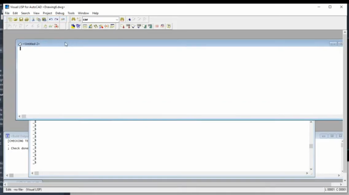
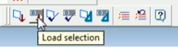
Hello, I working in this environment not possible anymore? I'm on AutoCAD 2025. It seems like working only in VS Studio Code is possible now. I liked the dedicated UI better. Biggest function I'm missing is the "Load Selection" button. Any way I can do something similar in VS Studio Code? If I revert back to the older versions, would working in the Visual LISP environment be possible?
-

AutoLISP routine not working in German AutCAD
Nikon replied to Vittorio's topic in AutoLISP, Visual LISP & DCL
I probably you need to add (_) before "off" (Command "_.-Layer" "_off" lay "") ??? I don't have the "_FREEZE" command in Autocad 2021. (Unknown "_FREEZE" command). But there is a command "_.LAYFRZ". To test the command, type "_FREEZE" on the command line. -

AutoLISP routine not working in German AutCAD
mhupp replied to Vittorio's topic in AutoLISP, Visual LISP & DCL
You cant freeze\off only the points its either the whole layer or nothing. this makes a selection set and process it to find what layers they are on and turns feezes and turns off those layers. if their are other things on that layer they will also be frozen and off. (defun c:test01 ( / ss lay laylst) (vl-load-com) (setq doc (vla-get-ActiveDocument (vlax-get-acad-object))) (setq layers (vla-get-Layers doc)) (if (setq ss (ssget "_X" '((0 . "AECC_COGO_POINT") (8 . "*-PT")))) (foreach ent (vl-remove-if 'listp (mapcar 'cadr (ssnamex ss))) (setq lay (cdr (assoc 8 (entget ent)))) (if (not (member lay laylst)) (setq laylst (cons lay laylst)) ) ) (foreach lay laylst (setq layerObj (vla-Item layers lay)) (vla-put-Freeze layerObj :vlax-true) (vla-put-Off layerObj :vlax-true) ) (prompt "\nNo matching COGO points found.") ) (princ) ) -

AutoLISP routine not working in German AutCAD
Vittorio posted a topic in AutoLISP, Visual LISP & DCL
Hi everybody, I'm trying to perform a very simple task, but the LISP just won't work on my German AutoCAD (Civil 3D 2025 German). I have a LISP routine to get all COGO points on layers with "-PT" suffix and want them to be turned off and frozen. (defun c:test01 (/ ss) (vl-load-com) (setq ss (ssget "_X" '((-4 . "<AND")(0 . "AECC_COGO_POINT")(8 . "*-PT")(-4 . "AND>"))) ) (command "_-layer" "freeze" ss "") (command "_-layer" "off" ss "") (sslength ss) (setq ss nil) (princ) ) I get an error upon running the LISP. Something like "invalid option keyword" since the -LAYER option "freeze" is called "frieren" in German. I've tried various command* combinations, but all fail. *) _-COMMAND or _.-COMMAND I'm lost here, those non-localized prefixes should work and I can't figure out why. Any help appreciated -
 NANGELIFE joined the community
 -
Avoiding Copy and Paste to secure clipboard data progress!
Nikon replied to ScottMC's topic in AutoLISP, Visual LISP & DCL
The character (_) is missing in these lines. (command "_chprop" "_L" "" "_la" "XLINE" "") ;; make xline grey Maybe that's the problem. -
 edsel sydy joined the community
 -
Avoiding Copy and Paste to secure clipboard data progress!
ScottMC posted a topic in AutoLISP, Visual LISP & DCL
Need someone to get this tool to crash for a test and get me to find solution. Had this previously using no entmake or trans but seems to work now. (defun c:4x (/ *error* pt1 pt2 ss ) (princ (strcat "\n 45"(chr 186)"/135"(chr 186)" 3D.XLines <!pp>")) (defun *error* ( msg ) (setvar 'cmdecho 0) (vla-endundomark (vla-get-activedocument (vlax-get-acad-object))) (if msg (prompt (strcat "\n" msg))) (setvar 'cursorsize 100) ;; reset to my prefer (setvar 'cmdecho 1) (princ) ) (setvar 'cursorsize 1) (entmakex ;; <LM '( (000 . "LAYER") (100 . "AcDbSymbolTableRecord") (100 . "AcDbLayerTableRecord") (002 . "XLINE") ;; Layer Name (070 . 0) ;; Layer Status (bit-coded) (006 . "Continuous") ;; Layer Linetype (must be loaded) (062 . 252) ;; Layer Colour (1-255) (290 . 0) ;; Non-Plot Flag (0=Plot, 1=NoPlot) (370 . -3) ;; Layer Lineweight (-3=Default) ) ) (defun zPoint ( / exv) ;; 3d point mfg (setq pt1 (trans pt1 1 0)) (setq exv (trans (list 0 0 1) 1 0 T)) (entmakex (list (cons 0 "POINT") (cons 10 pt1) (cons 210 exv))) ) (defun cdd () (princ "\n") (princ (setq pp ;; make/prints coords & paste usable (strcat (rtos (car pt1) 2 4) "," ;; 'p' -- vertex from pgm /\ getpoint,... (rtos (cadr pt1) 2 4) "," (rtos (caddr pt1) 2 4) ) ) ) (princ " cucs ");; ; (entmakex (list (cons 0 "POINT") (cons 10 pt))) ;; clean point (setenv "pp" pp) ;; crash saved coords ) ;;// ----------------------------------------------------------------------------------------------------------- ;; Get the initial placement point (while (setq pt1 (getpoint "\nSpecify Point for XLines: ")) (setvar 'cmdecho 0) (progn ;; Create a new empty selection set (setq ss (ssadd)) ;; Create horizontal xline and add to selection set (command "_.xline" "_a" 45 pt1 "") (command "chprop" "_L" "" "la" "XLINE" "") ;; make xline grey (ssadd (entlast) ss) ;; Create vertical xline and add to selection set (command "_.xline" "_a" 135 pt1 "") (command "chprop" "_L" "" "la" "XLINE" "") ;; make xline grey (ssadd (entlast) ss) (cdd) ;; post coords (zPoint) ;; point at 'pick.point ) (setvar 'cmdecho 1) ) ;; end of while (princ) ) -
place align block through lisp going wrong
mhupp replied to pmadhwal7's topic in AutoLISP, Visual LISP & DCL
Was more to show pmadhwal7 an alternative code with less checks but same functionality so you get the wrong layout faster with less compute! - Yesterday
-

place align block through lisp going wrong
BIGAL replied to pmadhwal7's topic in AutoLISP, Visual LISP & DCL
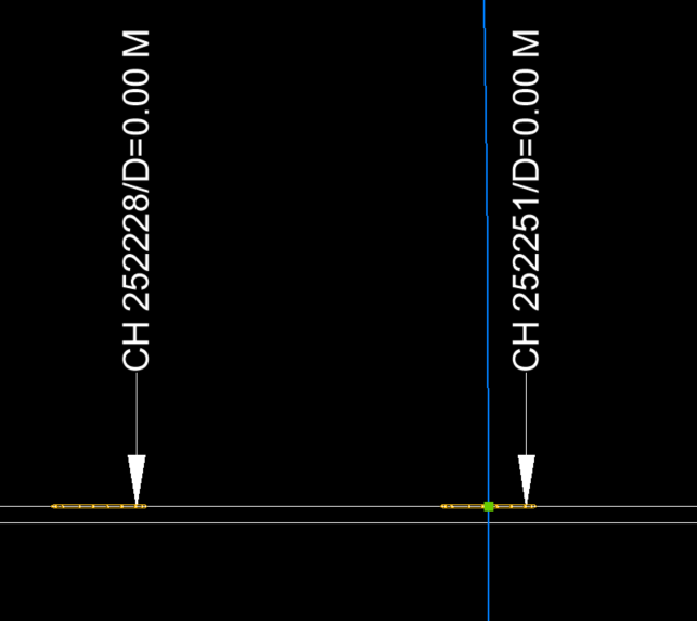
@mhupp did you look at my comment about the labels being at incorrect distance ? At the start they are correct and further along seem to have been shifted. A lot appear to have same incorrect offset. @pmadhwal7 I just made the blocks 1 unit long, just used BEDIT scale by 0,1 "0,0" then scale will be correct also turned off osnap. General comment given the chainage of the first label, 250414 the start of the pline is 250305, in label terms. Why is this start point not like 250300 which would make a lot more sense. Have used other pick label to set start chainage when testing. @pmadhwal7 need to know how are these labels being generated to a dwg. -
place align block through lisp going wrong
mhupp replied to pmadhwal7's topic in AutoLISP, Visual LISP & DCL
logic was wrong passing 1.0 if not a number and nil if (nth 3 data) & (nth 4 data) was a number should be fixed now. PIPE_InsertBlockFromCSV.lsp -
 zidann joined the community
 -

Top 20 AutoCAD Customizations – Part Two: Tuesday Tips With Frank
The AutoCAD Blog posted a topic in AutoCAD Blogs
Let’s get back to it with the second installment of the Top 20 AutoCAD customizations! If you missed it, be sure to check out part one with the first 10. Now, let’s take a look at numbers 11-20. And, again, we’ll list these in no particular order. 11. Command Line Docking When it comes to how you want to view your Command Line, much like the old hamburger ad campaign stated, you can have it your way. Using a left click press and hold on the left edge of default Command Line display, feel free to pull it off the bottom edge of the drawing editor. Make it shorter or larger by dragging an edge. If you want to put it back at the bottom, simply drag it back. When you get close enough, it will snap back into place for you. Maybe you’re like me and prefer the old school “in-line” display. This time, when you drag the Command Line, move it below the bottom edge, and it will be incorporated into the interface, now in its full view state. Either view will dock on any edge, so set it up how it works best for you. Or others! By that I mean that many of us who use a projected image of AutoCAD when teaching a class will place the Command Line at the top, where it can be seen easier by the students. 12. Status Bar Contents The Status Bar doesn’t display everything by default. Click on the customization icon in the lower right. Some people like to call this icon “the hamburger” (uh oh, do I feel a theme building or would that be considered cheesy?) If an entry doesn’t have a check mark, it is not currently displayed. Simply click on it to add it to the Status Bar. Conversely, there may be items that you don’t use. Do you never have the need to draw in Isometric mode? Save some space for something else by unchecking it here. 13. Ribbon Panel Options Similar to the Status Bar, your Ribbon doesn’t show everything by default. To manage your Tabs and Panels, right-click anywhere on the Ribbon to display two tools which display the available Tabs or Panels, and their visibility status. Much like the Status Bar, turn them on or off as needed. Perhaps there’s a tool that you’ll need to access often, but your workflow requires you to change tabs often, adding an extra and unnecessary step of changing tabs constantly. You can do a left-click press and hold on any black spot of a Panel, and drag it off the Ribbon and let it “float” elsewhere. When you’re done, you can click on the small icon in the upper right corner of the floating panel to return it to the position it was in on the Ribbon prior to floating it. 14. Maximize Viewport Do you ever need to work within a Paper Space viewport, but it’s rather small and your space is limited? You can maximize a viewport to fill the entire drawing editor. Simply double click on any edge of the desired viewport, and just like that, it expands to full view. Your visual clue is the large blue border that AutoCAD will display around the editor. Time to return to normal? Just double-click anywhere on the blue border. 15. Model Space Viewports Viewports aren’t just for Paper Space. This customization is extremely useful if you ever work in 3D. From the View tab of the Ribbon, expand the Viewport Configuration tool in the Model Viewports panel. Select from eleven preset layouts. Unlike Paper Space viewports, they are always tiled in Model Space. Just single click inside of any viewport to activate it. In the configuration shown below, it might be used to set one to be a top view, another a front view and another would be a side view. When you need to get back to normal, click on the Single option of the configuration pulldown, and the currently active viewport will display normally. 16. Startup Switches Customizing AutoCAD can be done outside of the interface as well. Did you know there are a number of things that you can have AutoCAD do when you double click on its desktop icon? They’re Command Line Switches, and (properly) adding them to the program’s icon can greatly increase your efficiency. You can tell AutoCAD to use a particular profile when it starts. You can specify a Sheet Set or a Template to start with. Maybe you want to run a particular Script or not display the splash screen — you can do that, too! Explore all of the available switches by clicking on this link to the reference table. 17. WYSIWYG In most modern graphics programs, you work in a What You See Is What You Get, or WYSIWYG environment. AutoCAD, as you know, displays in colors, then translates those colors or objects into the desired printed form. We use the Preview function to see what it will look like. But you can have AutoCAD display as WYSIWIG, and it’s as easy as clicking a single check box. From the pen assignments panel in the Page Setup dialog box, check Display Plot Styles. Having set this, you can see in our sample drawing below, the CTB/STB style of color display, verses the WYSIWYG style. I know of some firms that set an extra layout tab to display this way all the time. 18. Tool Palettes From Design Center Ah, we’ve come to the CAD Manager’s best friend. Tool palettes are an incredible design aid, and using them is fast and easy, as long as they’re already set up and ready to go. This is where the AutoCAD Design Center comes in. Do you need to create a tool palette of hundreds of blocks? Fire it up, navigate to either the folder or file that contains your blocks, right-click and tell it to create a tool palette. Easy peasy. Read all about it in the link below. For all my CAD Manager readers out there, I’m sorry for giving away one of our behind the curtain secrets. 19. View Transitions The AutoCAD drawing editor has improved its graphics in recent years. One of those improvements is the default ability to see the transition from one fiew to the next. You know, you zoom into an area, and you see the graphics zoom to, or transition to the new view. These are called Zoom Transitions and are controlled by a system variable called VTENABLE. To speed things up, you can turn this feature off by setting that varialbe to zero. Below are two animations. The top one shows the default transition settings, and the bottom one performs the same zoom with it turned off. VTENABLE set to its default of 3 VTENABLE set to zero (off) 20. Options Dialog Oh, there’s so much more. But I’m at 20, so it’s time to move on for me. But you can find all kinds of other ways to customize AutoCAD from the Options dialog. Click on the Display tab, and you’ll find that four of the six panels directly affect how you view and interface with AutoCAD. Do you like to have scroll bars displayed, and do you prefer for your crosshairs to be full screen? You can find those options and more here. That’s All Folks Hopefully between this blog and the last, you’ve found a little nugget or two that will make your AutoCAD sessions work a bit more like you do. To paraphrase an early AutoCAD influencer, until next time “keep on customizing.” More Tuesday Tips Check out our whole Tuesday Tips series for ideas on how to make AutoCAD work for you. The post Top 20 AutoCAD Customizations – Part Two: Tuesday Tips With Frank appeared first on AutoCAD Blog. View the full article -
 Selçuk joined the community
 -
 nhathanhvan joined the community
 -

Need a tool for creating 2d outlines for complex 2d drawings
Ankit Pandit replied to Ankit Pandit's topic in AutoLISP, Visual LISP & DCL
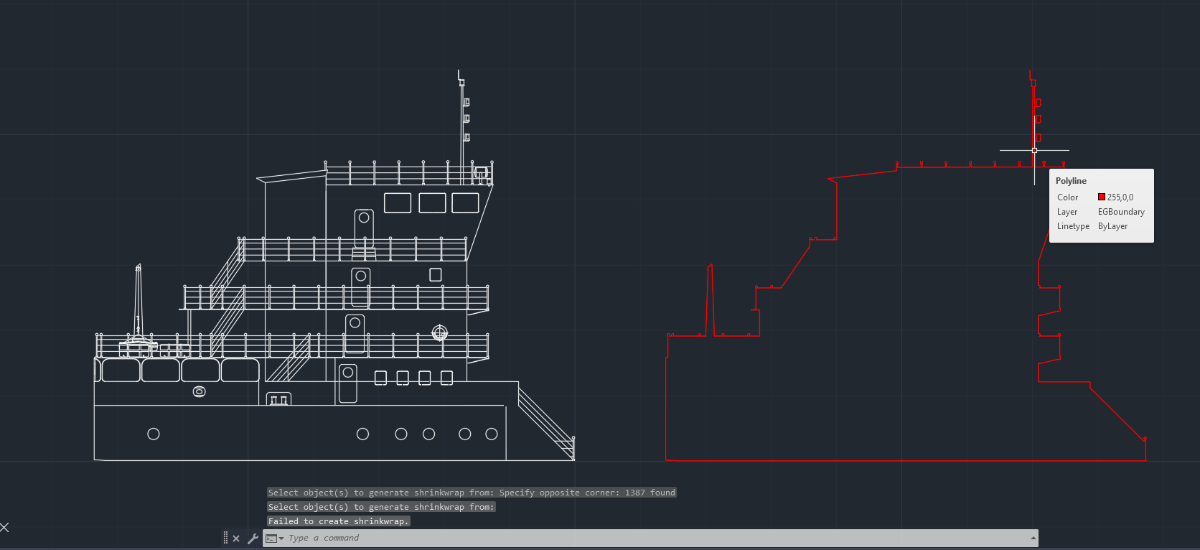
Here’s example from a different drawing where I tested both approaches. In this case, the shrinkwrap command wasn’t able to generate a boundary at all and returned a “failed to create shrinkwrap” message for this selection. Using the same input, I tried an alternative approach i.e. EGBoundary and was able to generate a clean, continuous outer boundary for the full shape. Sharing the comparison and .dwg file itself here. From what I’ve tested so far, the settings command seems to give a bit more control over things like automatic and manual tolerance handling as well as output customization (layer, color, etc.), which probably helps in these more complex cases. I’m still exploring it, but that flexibility seems to make a difference compared to the standard commands. For Clarification:- I am using AutoCAD Architecture 2026 and EGBOUNDARY for AutoCAD listed on their website. Part 6 Assm.dwg
-
 TOPOGRAFIE joined the community
 -
 nattapont.kkp joined the community
 -
 MecSoft Corporation joined the community
 -
place align block through lisp going wrong
BIGAL replied to pmadhwal7's topic in AutoLISP, Visual LISP & DCL
Ok just ran all 488 values and there may be a problem in your sample dwg the Chainage labels are not at correct chainage compared to the start point. I looked and the block did not align properly so checked the distance from start point for a random label and the blocks inserted are at the chainage but your label is not. The blue line is a circle with the radius set to the correct chainage you can see goes through middle of block but label does not match. So here is some code, note the blocks have been made 1 unit in length. I also changed the Excel to work out the mid point yes can be done with lisp but really why not use Excel. The dwg attached shows the problem. The Excel I used is attached. Yes part two needs to be done but need some answers to what I see as lots of problems in future dwg's. Drawing1-test.dwg test.lsp Book1.xlsx