All Activity
- Past hour
-

TotalBoundary • Outline creation tool
CraneGuy commented on Debalance's file in Programs and Scripts
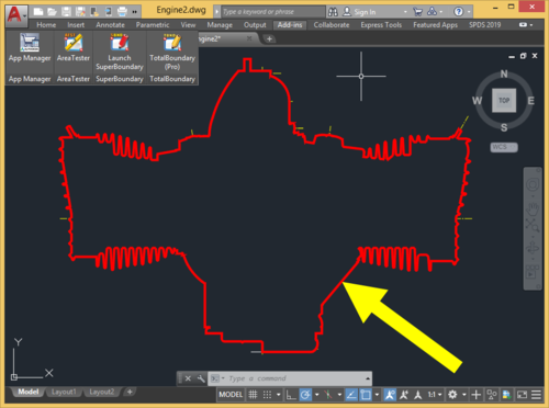 I appreciate your response. I even tried calling the number listed on the domain registration! No reply unfortunately. I used all the workarounds prior to finding TB, but the one click nature of it was invaluable. I messaged Lee Mac to see if he was interested in recreating TB...hopefully he'll be interested in adding the WIPEOUT element.
 -
No activity for a few years now and no responses on any forums/email, so could be anything. You might try Lee Mac's LISP. Some verticals have the SHRINKWRAP command, if you have the FREE tool pack and Architecture, it has SHRINKWRAP. You could create hatches, then a boundary and delete the hatches or just have them on a Frozen or No Plot layer.
-
It might help to provide a lot more information. Where did you get the LISP and what version? What exactly is the meaning of "most of my lisp routines work, but this one does not."? Should be some sort of error or doesn't load correctly, etc. if no error shown in CAD, try to run an error checker in your code editor. Do you have everything in a pathed folder?
- Today
-
 kaedep2210 joined the community
 - Yesterday
-
Thought I had posted this a dcl front end. (defun inputinfo ( / AH:setvals dcl des) (defun AH:setvals ( / ) (if(= (get_tile "Rb1") "1") (setq ztype "S") (setq ztype "D") ) (cond ((= (get_tile "Rb3") "1")(setq extop "F")) ((= (get_tile "Rb4") "1")(setq extop "P")) ((= (get_tile "Rb5") "1")(setq extop "N")) ) (setq extlen (atof (get_tile "val1"))) (princ) ) (setq dcl (vl-filename-mktemp "" "" ".dcl")) (setq des (open dcl "w") ) (foreach x '( "brklines : dialog {" " label =\"Please choose\" ;" " : row {" " : boxed_radio_column {" " width = 23 ;" " label =\"Single or Double\" ;" "spacer_1 ;" " : radio_button {" "key = \"Rb1\";" "label = \"Single\" ;" " }" "spacer_1 ;" " : radio_button {" "key = \"Rb2\";" "label = \"Double\" ;" " }" "spacer_1 ;" " }" " }" " : row {" " : boxed_radio_column {" " width = 23 ;" " label =\"Extend beyond picked points\" ;" "spacer_1 ;" " : radio_button {" "key = \"Rb3\";" "label = \"Fixed\" ;" " }" "spacer_1 ;" " : radio_button {" "key = \"Rb4\";" "label = \"Proportional\" ;" " }" "spacer_1 ;" " : radio_button {" "key = \"Rb5\";" "label = \"None\" ;" " }" "spacer_1 ;" " }" " }" " : row {" ": edit_box {" " label = \"Extension length\" ;" "spacer_1 ;" " width = 25 ;" "key = \"val1\" ;" " edit_width = 10 ;" " edit_limit = 9 ;" " is_enabled = true ;" " allow_accept=true ;" " }" " }" "spacer_1 ;" " ok_cancel ;" " }" ) (write-line x des ) ) (close des) (setq dcl_id (load_dialog dcl)) (if (not (new_dialog "brklines" dcl_id) ) (exit) ) (set_tile "Rb1" "1") (set_tile "Rb3" "1") (set_tile "val1" "50.0") (action_tile "accept" "(AH:setvals)(done_dialog)") (action_tile "cancel" "(done_dialog)(exit)") (start_dialog) (unload_dialog dcl_id) (vl-file-delete dcl) (princ) ) (inputinfo)
-
 Jgrand3371 joined the community
 -
Updated AISC Shapes for STL.LSP
Jgrand3371 replied to gtwatson's topic in AutoLISP, Visual LISP & DCL
I use this tool on a daily basis, so thank you for the update. I'm testing a trial version of Bricsys and most of my lisp routines work, but this one does not. Has anyone gotten it to work successfully in Bricsys? -
 juanjporras joined the community
 -

Dimangular-Vertex Macro Error
zaphod replied to zaphod's topic in The CUI, Hatches, Linetypes, Scripts & Macros
My fault for not stating all the angles were to be measured CW or CCW from 0°. -
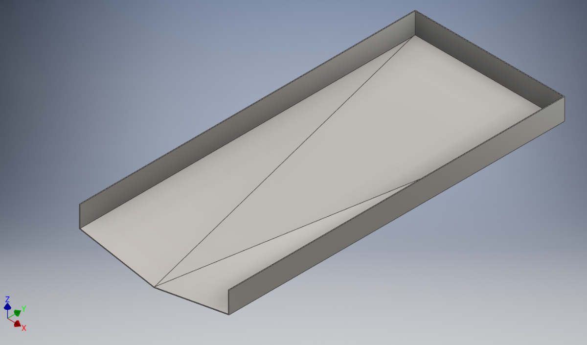
Hi all, I need your help please, to model up a "drip tray" like the one attached, but I need to do it in Inventor Sheet Metal so that I can obtain the flat pattern for laser cutting the material, which is 3mm Stainless Steel. I have done ones that slope to one corner but this one is slightly more complicated, and nothing I try works for me! The below is just an example of the shape, this is modelled form a solid block, which I just cut away the slopes & shelled it out to 3mm thickness. It has 3 slopes on the floor, so that the tray drains to the center at the front. The front plate will be welded on after as at is not possible to fold it as one piece anyway. My efforts involved creating each sloped section of the floor individually (using planes, sketches and faces), and trying to "flange" the vertical sides and then trying to join these up using the bend tool, but it just never works for me. The corners are probably just too complicates with all the different slopes and angles! Any help will be greatly appreciated, and thanks in advance for any help or advice on this. The bottom picture is the desired shape I am looking for as a flat pattern, I have attached a STEP file also Bottom Drip Tray 1460x650x3mm_ST.stp.stpz

-
 Denis_B joined the community
 -
TotalBoundary • Outline creation tool
CraneGuy commented on Debalance's file in Programs and Scripts
Does anyone know why they shut down? It was the best plugin for AutoCAD ever. It saved us a huge amount of time. Has anyone found anything comparable? -

Dimangular-Vertex Macro Error
pkenewell replied to zaphod's topic in The CUI, Hatches, Linetypes, Scripts & Macros
Ah Yes - those pesky object snaps getting in the way! What I meant was changing the starting axis from Y (0,0;0,1) to the X axis (0,0;1,0) for angles going CCW within 0 to 90 deg. Sounds like I misunderstood the problem though? -
Dimangular-Vertex Macro Error
zaphod replied to zaphod's topic in The CUI, Hatches, Linetypes, Scripts & Macros
solution from the Autodesk forums "*^C^C^C_dimangular;;non;0,0;non;0,1;\NON" -
Dimangular-Vertex Macro Error
zaphod replied to zaphod's topic in The CUI, Hatches, Linetypes, Scripts & Macros
Indeed, it is sir. Thank you for looking into this issue of mine. Although I'm not certain of what causes the error that I'm seeing, I have the same "Macro" written out on one of my gaming devices, it works, until AutoCAD becomes a dyslexic child. That caused me to look for an "internal" method to AutoCAD. Starting at around 2°, these were my results this morning. Multiple completely different random starting lines. I'm not sure what you mean by changing the start point, I want it to start on the 0° axis from 0,0. I do not use "Dynamic Input" or "Dynamic UCS".
-
 Saviel joined the community
 -
 staggers266 joined the community
 -

Pathfinding in AutoCAD with the A-Star Algorithm (A*)
Danielm103 replied to heschr's topic in AutoLISP, Visual LISP & DCL
Clever use of safe arrays -
 Frank.oli joined the community
 -

Pathfinding in AutoCAD with the A-Star Algorithm (A*)
ymg3 replied to heschr's topic in AutoLISP, Visual LISP & DCL
As I told you the advantage of this one is only when you have lots of edges and a long path. Acceleration comes from direct access with safearray when fetching value O(1) and replacing the openlist and updating directly in the heap. Mind you this is not a real heap as they have in C++ but probably the best we can do in Autolisp. There might be some optimizing left in the heap specially heap:pop and heap:push ymg -

Pathfinding in AutoCAD with the A-Star Algorithm (A*)
GLAVCVS replied to heschr's topic in AutoLISP, Visual LISP & DCL
Something interesting happens: There's little difference between the execution time of the Lisp version and the FAS version of your new code. And this FAS version isn't much faster than the previous one. The main advantage lies with Lisp. - Last week
-
Did you contact CADS RC about adding your own lisp programs I would do that as the first step in getting answers. There is some comments in the programming guide about add other lisps. Have you just tried running a lisp by pasting to the command line. (alert (strcat "this dwg name is " (getvar 'dwgname) " and is located at " (getvar 'dwgprefix))) Are you sure its a OEM version of Autocad ? If you type "About" what does it show. Talk to your IT the time savings can be hours a week using lisps, only use LSP files not FAS or VLX. A lsp file is a text file so you can see the code and look for anything that might be dangerous, like vl-file-delete, or only trust people like those here. You can get IT to check any code then add to your company directory location. This has like 130 lisps behind it.
-
if I read the manual provided by the link from SLW210 you should be able to create and (App)load your own lisp file with your own custom shortcuts (defun c:xx...). Lisp programming interface guide 2.1 Procedure to draw the reinforcement: 1. First draw the outlines with the required dimension. 2. Create a lisp file called demo.lsp in C:\ 3. Copy and paste the code mentioned below to the demo.lsp 4. Save it and close. 5. In AutoCAD use the Appload command to load the demo.lsp 6. Type Demo in the command prompt. It will ask you to pick the Lower Left corner of the base and the upper right corner of the base. Pick points p1 & p2 as mentioned in the drawing. 7. Specify the Cover and Centre to centre spacing. 8. You can see the reinforcement drawn on the screen. 9. Repeat step 6 & 7 for different footing outlines. But I'm just guessing here... never heard of this program so can't really tell. In the old days I smuggled my lisp routines in by creating a *.mnl file so my routines were loaded along with the menu (despite many efforts of a certain human who's name can't be spoken trying to stop users (specifically me) from being able to do their own stuff). Now many years later he admits dragons are very difficult if not impossible to stop (haha). Another way is starting AutoCad with your own custom profile by creating your own desktop shortcut (Google is your friend)
-
 idudodomu joined the community
 -
Dimangular-Vertex Macro Error
pkenewell replied to zaphod's topic in The CUI, Hatches, Linetypes, Scripts & Macros
LOL @zaphod - your username wouldn't be a reference to "Zaphod Beeblebrox" would it? Sorry i didn't answer you're OG question - just a Douglas Adams nerd haha. Seriously, I think the problem is the second point must be in a clockwise direction from the first line, meaning if you select an area in the first quadrant you are in a counter-clockwise rotation, and it will give you the obtuse side of the circle instead of the inside angle. For doing an angle from 0-90deg, you would need to start at 0,0;1,0 instead. -
 Juan B Once joined the community
 -
Dimangular-Vertex Macro Error
zaphod replied to zaphod's topic in The CUI, Hatches, Linetypes, Scripts & Macros
I did find a lisp on the Autodesk forums that will work for what I need, but I was really trying to get the macro to work. https://forums.autodesk.com/t5/visual-lisp-autolisp-and-general/command-for-multiple-angle-dims-picking-vertex-and-start-point/m-p/9637278 -

Penn Foster AutoCAD Applications-Construction assistance (Residential House Project)
TimC replied to TimC's topic in Student Project Questions
no they're not in pdf. Its website based -
Pathfinding in AutoCAD with the A-Star Algorithm (A*)
GLAVCVS replied to heschr's topic in AutoLISP, Visual LISP & DCL
-

Bolted Connections and Bracings SolidWorks Structure System
gabriele_biag posted a topic in SolidWorks
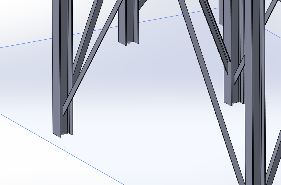
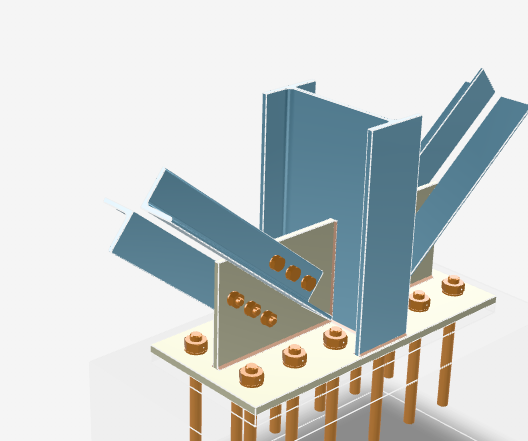
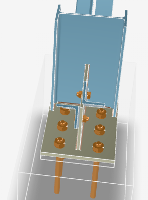
Hi everyone, I’ve recently started working with SolidWorks. After watching many tutorials I’ve begun to get familiar with the software, but I would like to ask for some advice regarding the Structure System module, as I couldn’t find online resources that cover my specific case. I need to model a steel frame structure. I managed to create a first general layout, but now that I have to add the bracing members and the related bolted connections, I’m starting to struggle. I understand how Connection Elements work, but what I need to achieve in my case seems difficult (or impossible) with the tools I currently know, so I’m here to ask for some guidance. This is the preliminary model I created (I don’t have access to the SolidSteel Parametric add-in). The type of connection I need to create is similar to the one shown in the image below. My main issue is with the bracing members: I can’t figure out how to insert them in order to obtain a double L-angle geometry (two angle profiles working together instead of a single profile). Using the Structure System, I can only insert one member at a time and I can’t find a proper way to manage this configuration. Since I’m also new to structural connections in general, I would really appreciate it if you could point me to: technical documentation or reference manuals guides, courses, or YouTube channels (English is fine) about steel structures and bolted connections SolidWorks-specific resources or best practices to learn proper structural modeling workflows Any advice, alternative approaches, or references would be extremely helpful. Thanks in advance to anyone willing to help!
-
gabriele_biag joined the community
-
I do not see anything specific stating the Lite version can do LISP. But, just in case, here is the manual for regular CADS RC. https://rebarcad.com/wp-content/uploads/2025/09/Lisp_Programming_Interface_Guide.pdf I also moved your thread to a new topic Use LISP with CADS RC Lite in AutoLISP, Visual LISP & DCL Forum
-
You should use the System Variable Monitor (SYSVARMONITOR), I also set my SYSVAR in my ACADDOC.lsp. You can export then import your settings and profiles before a Reset to Defaults, some things should be in your templates anyway, that would stay the same. So no, it is not a 'nuclear' option, that would be a complete removal and reinstall, and even then, you can restore a profile, settings, etc. and have proper templates.
-
Resetting to default definitely works as a 'nuclear' option, but for anyone else finding this thread who doesn't want to lose their UI setup, definitely check PICKFIRST and PICKADD first. If those variables get flipped to 0 by a glitch or a rogue LISP routine, it causes exactly this behavior where the Properties palette won't 'see' your selection.
-
Thanks Bigal for the info , I have CADS-RC lite program i have seen that the product has the access of using lisps and parameter files but i couldn't have any idea to add those packages in this product.