Leaderboard


Popular Content
Showing content with the highest reputation on 02/28/2025 in all areas
-
There is something similar. AutoDimPL.lsp2 points
-
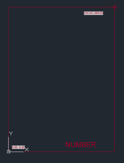
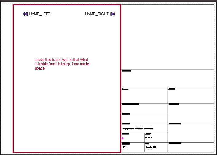
Hey @Nikon, If I can give you some advice. I had the same situation about 2-3 years ago, and I've been thinking about how to do automatization in creating layouts. And, I figure it out the best way (for my purpose) is to make differents "dwg" with appropriate size of viewports with accompanying "dwt" files (where are you going to have a "block" section with the name of company, number of project, name of the project, etc.). The first one is to make a different sizes of desired viewports. This one from picture 1 is for the 297x420 cm paper size. The second one is to make a "dwt" files where are you going to put your viewport inside the layout. The picture 2 show how it looks layout for the paper size 297x420 cm. The third one is coding (this is the first time when I created something using autolisp, the first program). It will look like this (this is the part from the code): (while (< i len) (setq base nil) (setq xy nil) (setq obj (ssname ss i)) (setq data1 (entget (ssname ss i))) (setq blockname (cdr (assoc 2 data1))) (cond ((= blockname L1) (setq data2 (entget (entnext (cdr (assoc -1 data1))))) (setq data3 (entget (entnext (cdr (assoc -1 data2))))) (setq data4 (entget (entnext(cdr (assoc -1 data3))))) (setq base (cdr (assoc 11 data3))) (setq xy (cdr (assoc 1 data3))) (setq no (1+ i)) (setq data4 (subst (cons 1 (itoa no)) (assoc 1 data4) data4)) (entmod data4) (setq nno (strcat v1 "." v2 "." (itoa no))) (setq path (findfile ".\\Situacioni plan saobracajne signalizacije_297x420.dwt")) (command "layout" "t" path "1") (command "layout" "s" "1") (command "layout" "r" "" nno) (command "mspace" "ucs" "ob" obj "plan" "c" "zoom" "w" base xy "pspace") ) ................... I hope I gave you some idea, it is simillar as @BIGAL proposal. Best regards.
 2 points
 -
Version 4.2.28.0
9,035 downloads
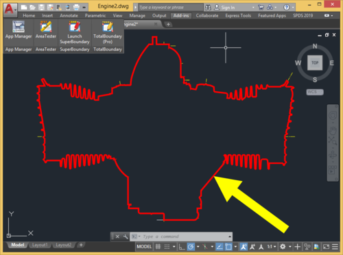
TotalBoundary (Pro) is a professional plugin for generating 2D outline drawings of various degrees of complexity with AutoCAD®. The outline drawings it creates are closed polylines marking the boundaries of various types of objects, which can include elementary entities (lines and arcs) as well as complex blocks and curves (ellipses and splines). What sets the TotalBoundary (Pro) utility apart from AutoCAD's built-in tools (such as BOUNDARY, BPOLY) and from other third-party programs is its high productivity and stability, and also the quality of the outlines it generates. The inbuilt algorithm for detecting spacing (gaps) between neighboring objects allows users to create enclosed outline polylines with exceptional accuracy. The program can process tens of thousands of objects extremely efficiently (in a matter of seconds), flawlessly generating highly complex outline polylines in the selected drawings. Key features: The program's powerful engine allows it to build enclosed polylines rapidly along the perimeter of selected drawing fragments. The original drawing needs no advance preparation (removing superfluous unconnected lines, creating an additional enclosed boundary polyline around the original drawing fragment). When the program creates an outline, it automatically identifies and removes gaps in places where primitives meet. The maximum size of these gaps can be set directly by the user. The program replaces splines and ellipses used in defining an outline with true polylines created by means of piecewise linear approximation. The user can also easily set the thickness and color of the polylines the program generates, if required. The program offers an automatic filling (solid hatching) option for the outlines it generates.1 point -
Hi Attach a drawing with which your code works1 point
-
I think a necessary improvement to all the codes proposed so far could be to get it to draw the dimensions on the side of the polyline desired by the user.1 point
-
You can use SSGET to make a selection of dims then simply change their style. Either a entmod or VL method. Maybe as simple as this. (defun c:wow ( / ss obj) (setq ss (ssget (list (cons 0 "DIM*")))) (repeat (setq x (sslength ss)) (setq obj (vlax-ename->vla-object (ssname ss (setq x (- x 1))))) (vlax-put obj 'StyleName "Standard") ) (princ) ) (c:wow) OOPs thought I posted this yesterday.1 point
-
Ok PM me I will talk via email. Yes you select scale and title block size, the title block is read from say a dwg containing all your layouts pre set up. Or can be made to match each title block that is inside the current dwg. As per code I posted all the size details are hard coded. You make say one or more rectang then just run step 2 and make the layouts. If you want different size then just run step one again. I need to see your title blocks in a dwg to work out settings. The other thing I did was a plottopdf.lsp that auto reads the title block name in a layout so matches correct plot settings again hard coded.
1 point
-
Fixed the X wall and also edited the prompt for the T so it's more explanatory. Like so: WALL-L X fixed.LSP
1 point