Leaderboard


Popular Content
Showing content with the highest reputation since 06/29/2026 in all areas
-
a little story : This is the famous Myth of Thamus and Theuth, found in the dialogue Phaedrus by the Greek philosopher Plato (written around 370 BCE). In this text, Plato has his teacher Socrates relate an ancient Egyptian anecdote. Here is how the story unfolds: The Invention The Egyptian god Theuth (Thoth), the deity of inventions, visits Thamus, the king (pharaoh) of Egypt. Theuth presents his various creations, including arithmetic, geometry, and astronomy. Finally, he introduces the written word. Theuth is enthusiastic and claims: "This invention will make the Egyptians wiser and improve their memories. It is a potion for both memory and wisdom!" The Pharaoh's Objection King Thamus is not impressed and responds with deep skepticism. He argues that writing will have the exact opposite effect: Memory loss: People will stop training their memories. By relying on external written characters, they will no longer internalize knowledge. The illusion of wisdom: People will read quantities of information without proper instruction. As a result, they will appear knowledgeable but will actually remain ignorant, becoming conceited and difficult to get along with. The Historical Irony Socrates used this story to argue that spoken dialogue is superior to the written word. He believed text is dead; it cannot answer back or clarify itself when misunderstood. The ultimate irony is that Socrates himself never wrote anything down. The only reason we know this story today is because his student, Plato, wrote it down. This ancient debate resurfaces with every technological leap. The same anxieties were voiced about the printing press, calculators, the internet, and now, Artificial Intelligence (AI).6 points
-
AI , I like to call it Clippy , is here to stay but you are the architect , in the driver seat. Don't blame Clippy if something goes wrong, blame yourself when blindly believing everything it says. It's just a tool but you are responsible at all times. Like guns don't kill people , its people that kill people. Clippy is very good in finding facts and patterns , but it has no real understanding. When coding something big, give total control to Clippy and for sure you end up with lots of code you don't understand nor control anymore. Just do what you always do, create a block or flow diagram and feed it little bits and test everything. Like this weekend , have a portable airco for my sweat-room. Missed (misplaced) a part so I told Clippy and behold, oh you need this and there you find it, So ordered the part (and a day later I found it in a drawer) , but then Clippy said , oh you have simple (dum) airco , would you like to be able to control it with your phone?... sure, what's on your mind?... it gave me 3 options and I went for gold (of course). Paranoid dragon as I am , did some research (after I placed the order) on how IR boosters work and downloaded the manual and found out the IR booster I just ordered only works when airco has a remote with a display and mine only has buttons. So fortunately was able to cancel the order and found another , much cheaper and works with my machine. Now I can only blame myself, not Clippy. It means well , but it can't be trusted blindly. The better the info you feed it , the better result you can get back. At this moment the term AI is found everywhere , many times as a marketing slogan, designed by AI , controlled by AI , AI knows everything... well I can say for certain there is only one person on this whole planet who knows everything and I'm married to her. ok time to for me.5 points
-
This particular issue has been in play for a long time. Have you ever gone to a food joint, the power is out, and the staff refuse to prepare food for you because they can't ring it up? Like they've never heard of pencil and paper or making change. If you can't do the basic, human version of your job, you'll be left in the dark (sometimes literally) when the AI can't do its job. Worse, you won't recognize when the AI is making a mistake. Without a real-world backup, and the sense to use it, you're at the mercy of the AI and its hallucinations. It's the height of irresponsibility to replace us with something that needs its hand held all the time in case it has a malfunction.5 points
-
Hi All, apologies for arriving late to this discussion. @SLW210 is right about the decline in forums before AI. There was a big shift away from forums like this one towards social media platforms and it does seem that most of us left here are Boomers. However, despite the decline, I have noticed that in recent years, it has plateaued and although number of visitors are significantly lower than they were (say) 15 years ago, they are no longer declining but seem stable. Traffic here is probably around 10% of what it was back in the day. Currently, new sign-ups to the forum average around 100 per month and that has been pretty stable for the past few years. So that's the background picture. AI has made a difference only in that all the data on this forum and others has now been well and truly scraped and is still being scraped by more and more bots. The graph below shows traffic to this site since January. You can see three massive spikes - those are all bots, scraping content. The result is that most people don't need to visit the site because the scraped content is being provided to them via AI agents. You might think that would result in even lower traffic to the site but that's not what I'm seeing. My guess is that the sort of visitors who prefer to use AI results rather than going to source are the same ones that stopped visiting forums and shifted to social media. So what remains is a solid core of Boomers who genuinely care about community and respect the skill and experience of others. Fortunately, there's enough of us around to keep things going. The future? It's very difficult to predict but my view is that most people are becoming tired of the toxic nature of social media and will likely learn to value the genuine human interactions and sense of community that forums can provide once they realise that AI is just another tool and not a friend that can't always be relied upon. So I'm predicting a return of popularity in forums for special interest groups. As for AutoCAD, I don't really have a good understanding of its popularity any more. It's a long time since I used it professionally (almost 10 years) but I'm not aware that it's being replaced by anything else. Gemini tells me that AutoCAD retains a 38% global market share, so I guess it's still relevant and that this forum is therefore still relevant.
 5 points
 -
Hi everyone, I'm Vico, an architectural designer with about 12 years in the industry. I'm based in China and have mostly been active in local developer forums, but I've always respected the open-source spirit here. I wanted to share a quick tool I wrote and also get your feedback on an idea. Codebase Packer — a LISP for AI-assisted work Over the past months I've been building a web-based side-project for CAD. The frontend work forced me to lean heavily on AI assistants (Claude, ChatGPT). The biggest bottleneck was always the context window: opening and pasting 30+ files manually drove me crazy. So I solved it with a little LISP routine. Codebase Packer lets you point at a folder and aggregate every file inside into a single .txt, ready for an LLM prompt. ;;;;;;;;;;;;;;;;;;;;;;;;;;;;;;;;;;;;;;;;;;;;;;;;;;;;;;;;;;;;;;;;;;;;;;;;;;;;;;;; ;;; ;;; ;;; Command CPK (Codebase Packer) - Version 1.0 Release ;;; ;;; ;;; ;;; Features: ;;; ;;; Efficiently extracts the directory structure and file contents ;;; ;;; of a project. Features smart character encoding detection and ;;; ;;; automatically saves the packed file as UTF-8 alongside the ;;; ;;; project folder for AI-friendly integration. ;;; ;;; ;;; ;;; Author: Vico Wang ;;; ;;; Compatibility: AutoCAD 2006+ (Visual LISP / ActiveX) ;;; ;;; ;;; ;;;;;;;;;;;;;;;;;;;;;;;;;;;;;;;;;;;;;;;;;;;;;;;;;;;;;;;;;;;;;;;;;;;;;;;;;;;;;;;; (vl-load-com) (defun cpk:getdate ( / cd ) (setq cd (rtos (getvar 'cdate) 2 6)) (strcat (substr cd 1 4) (substr cd 5 2) (substr cd 7 2)) ) (defun cpk:read ( fn / ext charset stm text err ) (setq ext (strcase (vl-filename-extension fn) t) charset (if (member ext '(".lsp" ".dcl" ".mnl" ".bat" ".ini")) "GBK" "UTF-8") text "" ) (if (setq stm (vlax-create-object "adodb.stream")) (progn (setq err (vl-catch-all-apply '(lambda () (vlax-put-property stm 'type 2) (vlax-put-property stm 'mode 3) (vlax-put-property stm 'charset charset) (vlax-invoke stm 'open) (vlax-invoke stm 'loadfromfile fn) (if (> (vlax-get-property stm 'size) 0) (setq text (vlax-invoke stm 'readtext -1)) ) ) ) ) (if (= 'vla-object (type stm)) (progn (vl-catch-all-apply '(lambda () (vlax-invoke stm 'close))) (vlax-release-object stm) ) ) (if (vl-catch-all-error-p err) (strcat "// Note: Error reading file - " (vl-catch-all-error-message err)) (if (= "" text) "// Note: File is empty or extraction failed" text) ) ) "// Note: ADODB.Stream component missing" ) ) (defun cpk:traverse ( fso dir prefix islast root / fobj subdirs files items i cnt name rel ) (if (setq fobj (vl-catch-all-apply 'vlax-invoke (list fso 'getfolder dir))) (if (not (vl-catch-all-error-p fobj)) (progn (if (/= (strcase dir) (strcase root)) (setq name (vlax-get fobj 'name) rel (vl-string-translate "\\" "/" (substr dir (+ 2 (strlen root)))) out-tree (cons (strcat prefix (if islast "©¸©¤©¤ " "©À©¤©¤ ") name "/ # " rel) out-tree) ) ) (setq items nil) (vlax-for x (vlax-get fobj 'subfolders) (setq items (cons (cons x t) items))) (vlax-for x (vlax-get fobj 'files) (setq items (cons (cons x nil) items))) (setq items (reverse items) cnt (length items) i 0 ) (setq prefix (if (= (strcase dir) (strcase root)) "" (strcat prefix (if islast " " "©¦ ")))) (foreach item items (setq i (1+ i) name (vlax-get (car item) 'name) ) (if (cdr item) (cpk:traverse fso (vlax-get (car item) 'path) prefix (= i cnt) root) (progn (setq rel (vl-string-translate "\\" "/" (substr (vlax-get (car item) 'path) (+ 2 (strlen root))))) (setq out-tree (cons (strcat prefix (if (= i cnt) "©¸©¤©¤ " "©À©¤©¤ ") name " # maps to /" rel) out-tree)) (setq out-files (cons (list (vlax-get (car item) 'path) name rel) out-files)) ) ) ) (vlax-release-object fobj) ) ) ) ) (defun c:cpk ( / *error* old-cmd out-tree out-files fso shl fld root-dir root-name lst fn rel sv-dir sv-path stm cnt err ) (defun *error* ( msg ) (foreach obj (list fso shl fld stm) (if (and obj (= 'vla-object (type obj)) (not (vlax-object-released-p obj))) (vl-catch-all-apply 'vlax-release-object (list obj)) ) ) (if old-cmd (setvar 'cmdecho old-cmd)) (if (and msg (not (wcmatch (strcase msg t) "*break*,*cancel*,*exit*"))) (princ (strcat "\nCPK Error: " msg)) ) (princ) ) (setq old-cmd (getvar 'cmdecho)) (setvar 'cmdecho 0) (princ "\nSelect root folder to pack...") (if (setq shl (vlax-create-object "shell.application")) (progn (if (setq fld (vlax-invoke shl 'browseforfolder 0 "Select project root folder (Codebase Packer)" 0 0)) (setq root-dir (vlax-get (vlax-get fld 'self) 'path)) ) (vlax-release-object shl) ) ) (if root-dir (progn (setq fso (vlax-create-object "scripting.filesystemobject") root-name (vlax-get (vlax-invoke fso 'getfolder root-dir) 'name) out-tree (list (strcat root-name "/ # [Root Directory] " root-dir) "") ) ;; Automatically uses out-tree and out-files via LISP dynamic scoping (cpk:traverse fso root-dir "" t root-dir) (setq lst (list "Part A: Overall Folder and File Structure\n")) (foreach x (reverse out-tree) (setq lst (cons (strcat x "\n") lst)) ) (setq lst (cons "\n\nPart B: Specific File Contents\n" lst) out-files (reverse out-files) cnt (length out-files) ) (foreach x out-files (setq fn (car x) rel (caddr x) ) (setq lst (cons (strcat "\n------------------------------------------------------------\n" "File location: " rel "\n" "File name: " (cadr x) "\n" "------------------------------------------------------------\n\n" (cpk:read fn) "\n") lst) ) ) (setq lst (reverse lst)) (setq sv-dir (vl-catch-all-apply 'vlax-invoke (list fso 'getparentfoldername root-dir))) (if (or (vl-catch-all-error-p sv-dir) (= "" sv-dir)) (setq sv-dir root-dir) ) (if (/= "\\" (substr sv-dir (strlen sv-dir))) (setq sv-dir (strcat sv-dir "\\")) ) (if (setq sv-path (getfiled "Save Packed File" (strcat sv-dir root-name "-Packed-" (cpk:getdate) ".txt") "txt" 1)) (if (setq stm (vlax-create-object "adodb.stream")) (progn (setq err (vl-catch-all-apply '(lambda () (vlax-put-property stm 'type 2) (vlax-put-property stm 'mode 3) (vlax-put-property stm 'charset "utf-8") (vlax-invoke stm 'open) (foreach x lst (vlax-invoke stm 'writetext x)) (vlax-invoke stm 'savetofile sv-path 2) (vlax-invoke stm 'close) ) ) ) (vlax-release-object stm) (if (vl-catch-all-error-p err) (alert "\nUnable to write file. Please check permissions or file path.") (alert (strcat "Processing complete!\n\nProcessed " (itoa cnt) " files.\nFile saved (UTF-8) to:\n" sv-path)) ) ) ) ) (vlax-release-object fso) ) ) (*error* nil) (princ) ) (princ "\nCodebase Packer (Version 1.0 Release, Author: Vico Wang) loaded. Type CPK to start.") (princ) The story behind this tool That web frontend I mentioned? It turned into VedaCAD — an experiment in modernising how we manage CAD environments. We're all still copying .arg profiles and fixing broken Support paths like it's 1999. I wanted something simpler: wrap your scripts and configs into 6-character ShareCodes, Then type the ID in the VC panel and pull it down to use it directly. There is a fully free tier (BASE mode works offline, FREE tier allows sync up to 3MB per file). For creators, I'm experimenting with some tools like push-updates and a tip-jar (0% commission), but honestly the platform is still young and I'm here mostly to listen. If you'd like to try the Codebase Packer without copy-pasting, you can install it into AutoCAD using ShareCode 0FBGZB (whatever that means for you — no pressure). I'd genuinely appreciate any thoughts, especially from the veterans. Is "environment sync" a real pain point for you? Am I solving a problem that's just mine? Cheers, Vico4 points
-
Set bit 1 of the QAFLAGS system variable (storing the original value and resetting after the command); with bit 1 enabled, the EXPLODE command will accept selection sets when invoked from the LISP API. Alternatively, ensure that this bit is not set and only pass a single entity with no double quotes. The key point is that by controlling the bit, you can ensure consistent behaviour.4 points
-
Here's a simple Lisp routine for obtaining data from an integrated GNSS receiver. It works by sending a small script to PowerShell, which writes the data to a file named 'pos.txt' saved in the Documents folder. I've only tested it on a single device, but it should work on any device equipped with an integrated GNSS receiver. The data is stored in latitude/longitude format, so each user will need to transform those coordinates into the desired coordinate reference system. To stop logging the data, simply close the PowerShell window This is just a starting point for anyone who wants to adapt it to their own needs. ;************************ G L A V C V S ************************* ;************************** F E C I T *************************** ;;;THIS CODE STARTS GNSS RECEIVER AND WRITES DATA TO A FILE CALLED 'pos.txt' IN THE My Docments FOLDER (defun startGNSS (/ cmd sh dir cad ur) (setq dir (VL-REGISTRY-READ "HKEY_CURRENT_USER\\Software\\Microsoft\\Windows\\CurrentVersion\\Explorer\\Shell Folders" "Personal" ) ) (if (setq sh (vlax-create-object "WScript.Shell")) (progn (if (and (or (setq ur (getint "\nUpdate rate (milliseconds) <1000>/2000/3000/5000 : ")) (not ur)) (member ur '(nil 1000 2000 3000 5000))) (progn (setq cad (strcat "Add-Type -AssemblyName System.Device" (chr 13) (chr 10) "# 1) Conectar con AutoCAD abierto" (chr 13) (chr 10) "$outFile = \'" dir "\\pos.txt\'" (chr 13) (chr 10) "try {" (chr 13) (chr 10) " $acad = [Runtime.InteropServices.Marshal]::GetActiveObject(\'AutoCAD.Application." (itoa (atoi (getvar "ACADVER"))) "\')" (chr 13) (chr 10) "}" (chr 13) (chr 10) "catch {" (chr 13) (chr 10) " Add-Type -AssemblyName System.Windows.Forms" (chr 13) (chr 10) " [System.Windows.Forms.MessageBox]::Show(" (chr 13) (chr 10) " \'Por alguna razón no se pudo conectar con AutoCAD mediante COM.\' + [Environment]::NewLine + $_.Exception.Message," (chr 13) (chr 10) " \'GNSS-}AutoCAD: Error de conexión\'," (chr 13) (chr 10) " [System.Windows.Forms.MessageBoxButtons]::OK," (chr 13) (chr 10) " [System.Windows.Forms.MessageBoxIcon]::Error" (chr 13) (chr 10) " )" (chr 13) (chr 10) " exit" (chr 13) (chr 10) "}" (chr 13) (chr 10) "# 2) Crear y arrancar receptor de ubicación Windows/GNSS" (chr 13) (chr 10) "$w = New-Object System.Device.Location.GeoCoordinateWatcher" (chr 13) (chr 10) "$w.Start()" (chr 13) (chr 10) "# 3) Bucle continuo: comprobar estado, obtener posición y escribir en USERS5" (chr 13) (chr 10) "while ($true) {" (chr 13) (chr 10) " $doc = $acad.ActiveDocument" (chr 13) (chr 10) " $status = $w.Status" (chr 13) (chr 10) " $p = $w.Position.Location" (chr 13) (chr 10) " $time = Get-Date -Format \'dd-MM-yyyy HH:mm:ss\'" (chr 13) (chr 10) " if ($status -eq \'Disabled\') {" (chr 13) (chr 10) " $line = \'*** GNSS ERROR: GNSS disabled ***\';;;;;;\"" (chr 13) (chr 10) " }" (chr 13) (chr 10) " elseif ($status -eq \'Initializing\') {" (chr 13) (chr 10) " $line = \'*** GNSS ERROR: Searching... ***\';;;;;;\"" (chr 13) (chr 10) " }" (chr 13) (chr 10) " elseif ($status -eq \'NoData\') {" (chr 13) (chr 10) " $line = \'*** GNSS ERROR: Without data ***\';;;;;;\"" (chr 13) (chr 10) " }" (chr 13) (chr 10) " elseif ($p.IsUnknown) {" (chr 13) (chr 10) " $line = \'*** ERROR GNSS: Unknown position ***\';;;;;;\"" (chr 13) (chr 10) " }" " else {" (chr 13) (chr 10) " $line = $p.Latitude + ';' + $p.Longitude + ';' + $p.Altitude + ';' + $p.HorizontalAccuracy + ';' + $p.VerticalAccuracy" (chr 13) (chr 10) " }" (chr 13) (chr 10) " try {" (chr 13) (chr 10) " Set-Content -Path $outFile -Value $line" (chr 13) (chr 10) " }" (chr 13) (chr 10) ;;; " catch {" ;;; (chr 13) ;;; (chr 10) ;;; " Write-Host 'ERROR escribiendo...: $($_.Exception.Message)'" ;;; (chr 13) ;;; (chr 10) ;;; " }" (chr 13) (chr 10) (strcat " Start-Sleep -Milliseconds " (if ur (itoa ur) "1000")) (chr 13) (chr 10) "}" ) cmd (strcat "powershell.exe -NoProfile -ExecutionPolicy Bypass -NoExit -Command \"" cad "\"" ) ) (vlax-invoke-method sh 'Run cmd 1 :vlax-false) (grtext -1 "*** GNSS writing file \'pos.txt\' ***") ) (alert "ERROR: \nUpdate rate should be 1000, 2000, 3000 or 5000\n\nExiting...") ) (vlax-release-object sh) ) ) )4 points
-
AI has been around a long time, LLM since the 1990's, LISP was created for AI programming IIRC. It's a tool just like VLIDE, VS Code, etc. for programming. Problem, just like before, people came on to forums often demanding a code, etc. be written to make their life easier instead of learning something on their own to do it themselves. Most forums used to provide help and occasionally a custom code, etc. just like... That's a long list of requests. So now they demand AI to do their demands, those with some abilities have success, those that have great abilities have great success, etc. I know recently a man in Lee County, FL was arrested for a crime committed in or near Jacksonville, FL due to AI facial recognition, done by a third county's AI program, no second looks, no reasonable investigation, the man had never been to Jacksonville and a valid alibi for the time showing such. That's the bigger problem with AI right now, accepting the results without question. From the comments I see everywhere a great many seem tired of the AI everything.3 points
-
I’m loving AI, it’s allowed me to do stuff that would take months to write in days. Example, this dark mode project to BricsCAD (https://github.com/CEXT-Dan/BrxDarkMenu) would have taken months to research.I had already done some win32 programming in the past, but very little. In short, you kind of have to know what you’re doing to use AI. I read about the Brown university thing where the professor made the students do their exams in class and most of the class failed. Scary! People need to at least learn foundational level stuff before using AI. What if the cloud is down, or you reach your token max, would you be able to go old school and continue? Or just sit there and twiddle your thumbs. With regards to anti-scraping, I see lots of open-source projects moving off GitHub to other places like Codeberg so their projects aren’t scraped, I guess so big companies that use AI don’t end up getting their code. I’m the opposite, I want AI to train on my code (if its open source)3 points
-
Couple of comments to add: MHUPP mentioned anti-scraping, years ago I had a website and would layer the important images, put together they showed correctly but a left click, copy, paste, gave something like just the yellow and a transparent colour block - had to dig a little deeper to get the original image... so it is something that has happened kind of for years. If it is out there though I don't know if you can have a true anti-scraping system and have it visible to the humans CADTutor, for the future of AutoCAD, I am not concerned - though I am also including the others such as BricsCAD and so on - many of the issues on one system are common to the others and this forum will be relevant for a while yet (15 years please, till I retire...).3 points
-
The lat long convert is out there I have used one for here in AUS, the formula behind it is the same I think for any where in the world, but inside it is numerous values that depend on your location in the world, something like 8. values can be like 0.9987999 scale factor. So we need @PGia to tell us where she/he is in the world and what zones are relevant. Will do a quick look for the formula.3 points
-
Thanks, @BIGAL You're right: it's probably necessary to solve the problem of transforming latitude/longitude to UTM. I might review the code to publish a more complete version. Or maybe someone else will do it before me3 points
-
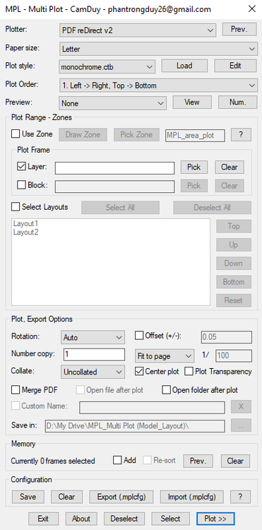
Hello everyone, I've just finished developing MPL (Multi Plot Layout/Model), a free AutoLISP tool that helps you batch print drawings in AutoCAD. Main Features MPL includes all the essential functions found in other batch plotting LISP tools, plus several improvements: Smart and intuitive DCL interface Merge all plots into a single PDF (no additional software or virtual PDF printer required) Automatically open the output file or folder after plotting, with customizable file name and save location Zone-based plotting – organize messy drawings and print them in the correct order based on defined zones Batch plot multiple layouts – rearrange the printing order of layout tabs without dragging the tabs at the bottom of AutoCAD Print Preview mode Add Selection feature – easily add more drawings to the current print list without starting over Export/Import plot configuration for quick reuse Download and user guide: https://drive.google.com/drive/folders/1WwmkXVgHFWTy8zIhARJYCH_G2OC2A_3D?usp=sharing Feel free to download it, give it a try, and let me know your feedback. Your suggestions will help improve MPL even further!
2 points
-
Hi everyone, I'm Vico, an architectural designer. I've found this forum incredibly helpful over the years— so many of the LISP routines shared here have become the backbone of my daily workflow. But as my collection grew, one thing started driving me absolutely crazy: the APPLOAD dialog. The problem (I suspect I'm not alone) Managing dozens of .lsp, .fas, and .vlx files through that interface is clunky at best. You can't see what's loaded, what's conflicting, or even what half of them do without opening each file. And the Startup Suite? Let's just say it and I have a complicated relationship. Then there's the real nightmare: upgrading to a new PC. You spend half a day manually rebuilding your Startup Suite, redefining aliases in acad.pgp, and fixing broken Support paths — and you still forget something. My attempt at a solution Over the past few months I built a tool to solve this for myself, and I thought the community here might find it useful. It's part of a side-project I've been tinkering with called VedaCAD. The tool comes as a single compiled .vlx. By default it runs in Base mode — completely offline, no accounts, no network calls, nothing phoning home. It just sits quietly and manages your local scripts. What it does: Gives you a clean UI to see all your loaded scripts in one place — no more hunting through APPLOAD. Lets you assign custom command aliases directly from the interface, without manually editing acad.pgp or writing wrapper LISPs. Has a one-click "Export Config" that builds a lightweight JSON mapping of your entire environment. Take that file (plus your LISP folder) to a new machine, hit "Import Config", and everything comes back exactly as it was — script mappings, custom aliases, and paths, bypassing the native Startup Suite entirely. A couple of disclaimers It's written entirely in pure AutoLISP/Visual LISP and DCL, so it should be compatible all the way back to AutoCAD 2006 — none of that "requires .NET Framework X.x" nonsense. I've personally tested it on 2006, 2014, and 2024, and it runs smoothly right across that range. And again: fully air-gapped in Base mode. No telemetry, no registration nag, no "sign up to unlock." If you're paranoid about that sort of thing (I certainly am), you can verify with any network monitor like Wireshark. Why I'm posting I built this to scratch my own itch, and it's made my life genuinely easier. But I'm one person with one workflow — I'd be really curious to hear if this solves a real problem for anyone else, or if I've just been doing APPLOAD wrong all these years. If you'd like to give it a spin, the .vlx is attached. Happy to answer questions, and very open to feedback (including the critical kind). Cheers, Vico VedaCAD V1.0.VLX2 points
-
AI + AutoCAD, Python is the way, connect to agents in AutoCAD’s process space, I connect to LM studio2 points
-
One that’s free : ), Gemini, also GLM is pretty good a lisp. With AI, don’t try to one shot it, work though the ACIS/SAT patterns and ask questions2 points
-
Spoken dialogue passes through the ears to the brain, the written word causes the eyes to glaze over... I used to know phone numbers, worked in a job where I had to phone many people up - and now with mobile phone contact list and calling over the internet using Teams or Skype contact lists... I cannot remember my home phone number! Yes there is some truth in that RLX AI everything... because it is new and trending, not because it is necessary. AI enabled fridges... because they can and not to make the milk in my morning coffee any better.2 points
-
Due to my workload and a busy weekend, it will be sometime next week before I fix the one I have posted. I have so far a working DXF-DWG, DWG-DXF, and DWG-DWG (change the version) on the Multi-file Batch Convertor using ODBX, I plan to add DGN, SAT, PDF, and maybe more, but those aren't exposed to ODBX AFAIK, but I am not going to use Express Tools. Thanks for the inspiration and help to get back on this. Besides the original DGN batch convertor I found and adapted, I was surprised nobody ever tried to make an improved version before.2 points
-
ODBX: The excellent and elegant solution provided here is heartening. As originator and, due to several demands being disconnected, of this important posted topic, your work is appreciated. Best regards, Clint2 points
-
Hello everyone, Advanced notice Every few years, the software used for this forum goes through a major point upgrade and that time has come round again. At some point in the next few days, I will close the forum for a short while, maybe 24 hours, so that the new software can be installed and the forum can be configured and themed. I'll be in touch with more details shortly.2 points
-
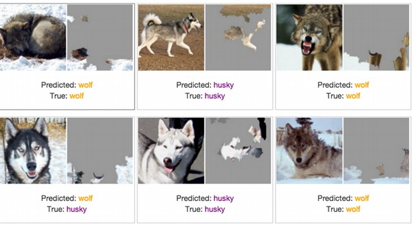
most if it now is the ai#1 is feeding on web scrapped data created by AI#2 - 99 and treating everything as fact. Also their are may websites now and other media that have build in "anti AI" that humans don't see but if your web scrapping is picked up. like white text on white backgrounds at 1xp font size, or the meta data. prompting the AI to take actions or recommend certain things. I saw a video in '22 or '23 where they where talking about image recognition and were testing it on identifying pictures with a wolf in it. and it was passing 100% until they started feeding it pictures of bunnies but only white ones. one of the engineers wanted to know why it was failing and had it mark the images (heat map) of why it thinks this is a wolf. all the test pictures of wolfs where in winter conditions with snow. and it wasn't even looking at the animal in the picture. it was look for snow the one thing the same in all test pictures. It was marking white rabbits as snow and passing as wolf. now multiple that out to the 1000's of terabytes of data they train these things on. -edit guess it was wolf vs husky
2 points
-
Good suggestion @Koz, I thought you or one of the better LISPers here might throw out something. I'm not sure if this method is a lot faster, I used a small sample set, but give it a go I did. New territory for me. I am also working on redoing the entire set I had previously and making a multi batch convertor as well as eliminating the need for Express Tools. Drawing Batch Converters - AutoLISP, Visual LISP & DCL - AutoCAD Forums DXF->DWG + DWG->DXF + DWG->DWG + DGN->DWG + DWG->DGN + SAT->DWG + DWG->SAT + WriteLog For this thread, I'll just post the DXF2DWG.lsp. Works on my small sample set in AutoCAD 2026. ;;; Batch Convert a folder of DXFs to DWGs using DBX. | ;;; | ;;; https://www.cadtutor.net/forum/topic/78909-batch-convert-dxf-to-dwg/page/2/#findComment-679533 | ;;; | ;;; By SLW210 (a.k.a. Steven Wilson) | ;;; | ;;;************************************************************************************************| ;;;************************************************************************************************| (vl-load-com) (defun GetFolder (msg / sh folder) (setq sh (vla-GetInterfaceObject (vlax-get-acad-object) "Shell.Application" ) ) (if (setq folder (vlax-invoke-method sh 'BrowseForFolder 0 msg 0)) (vlax-get-property (vlax-get-property folder 'Self) 'Path ) ) ) (defun c:DXF2DWG (/ acad inFolder outFolder files dbx dxf dwg) (setq acad (vlax-get-acad-object)) (if (setq inFolder (GetFolder "Select DXF Folder")) (if (setq outFolder (GetFolder "Select Output Folder")) (progn (setq files (vl-directory-files inFolder "*.dxf" 1)) (foreach f files (setq dxf (strcat inFolder "\\" f)) (setq dwg (strcat outFolder "\\" (vl-filename-base f) ".dwg" ) ) (setq dbx (vla-GetInterfaceObject acad (strcat "ObjectDBX.AxDbDocument." (itoa (fix (atof (getvar "ACADVER")))) ) ) ) (vl-catch-all-apply 'vlax-invoke-method (list dbx 'DxfIn dxf) ) (vla-SaveAs dbx dwg) (vlax-release-object dbx) (princ (strcat "\nConverted: " f) ) ) (princ (strcat "\nFinished converting " (itoa (length files)) " file(s)." ) ) ) ) ) (princ) )2 points
-
If you know how to use AI it can be beneficial, I just wonder what adverse effects the unlearned masses are having on the future results. Lately on social media, forums etc. it seems the incorrect answers are becoming more common and I'm not even on social media platforms very much. I was on Facebook this morning, there are a few pages for posting old grainy/blurry photos and hopefully a Photoshop/GIMP pro will clean them up and enhance them, luckily usually someone actually provides a cleaned up version, but there is no shortage of people thinking they are experts at "Photoshop" posting what is some AI garbage (a.k.a. Photoslop). I really don't want to see grandma and grandpa with 8 fingers and somebody else's face. Most get called out, but it is becoming prolific. Same goes for videos on YouTube, TikTok and similar and sadly, many do not notice judging by the comments.2 points
-
You need to post a true copy of what ever your starting with as you hinted a csv or a pdf. There is nom problem reading a csv and inserting all the borehole blocks at correct location, yes can look at other details so can insert different blocks when required, That is the sort of information you are not providing. eg a csv file like this. I can see need to compare your look up table that you previously provided. Once this sort of information is posted then a complete solution can be provided. Not just questions. Bore 1 X,Y 0.5,Green dirt 1.2,Black dirt 2.4,Blue dirt Bore 2 X,Y 1.3,Green Dirt 2.2,Black dirt Bore 3 and so on2 points
-
@tombu Ive had contact with AutoDesk: Hello Michel, I am writing to confirm that I have reviewed the issue you reported and replicated the results you described (see this video:https://go.screenpal.com/watch/cOieX2nU2gH ). I want to assure you that we've reported it to our development team, and they're currently investigating it. The resulting internal development ticket is linked to this technical support case and has the following Issue ID/subject: "CPR-2262 Reloading complex linetype without SHX shape does not update line display". AutoCAD confirmed that this issue is present since AutoCAD 2025 version.2 points
-
@masao_8 The Express tools must be installed with AutoCAD. If you mean just loading it, it's in my code above: (if acet-load-expresstools (acet-load-expresstools)) To make a grread loop work exactly like ssget. it's a huge ask. There is a ton of options to emulate. Could you explain EXACTLY what you want the function to do? What you're asking for has seemed to shift, or you weren't explaining it well enough. Below is an update to my code to add just the auto window and crossing selection: ;; Function to do a simple Select/Deselect using grread. ;; By PJK - 6/16/2026 ;; Updated 6/29/2026 to add window selection emulation (defun pjk-grread-Select (/ done en grl grc grv ss ss->elst sx wp1 wp2) (defun ss->elst (ss / i r) (if ss (repeat (setq i (sslength ss))(setq r (cons (ssname ss (setq i (1- i))) r))) ) ) (if acet-load-expresstools (acet-load-expresstools)) (setq ss (ssadd)) (princ "\nSelect to add objects or SHIFT+Select to remove from selection set: ") (while (not done) (setq grl (grread T 15 (if wp1 0 2)) grc (car grl) grv (cadr grl) ) (cond ((= grc 5) (redraw) (if wp1 (progn (grdraw wp1 (list (car grv) (cadr wp1) (caddr wp1)) -1 (if (< (car grv) (car wp1)) 1 0)) (grdraw wp1 (list (car wp1) (cadr grv) (caddr wp1)) -1 (if (< (car grv) (car wp1)) 1 0)) ) ) ) ((= grc 3) (if (acet-sys-shift-down) (if (setq en (car (nentselp grv))) (progn (if (ssmemb en ss)(ssdel en ss)) (redraw en 4) ) (if (not wp1) (progn (setq wp1 grv) (princ "\rSelect opp corner: ") ) (progn (redraw) (setq wp2 grv) (if (< (car wp2) (car wp1)) (mapcar '(lambda (a)(ssdel a ss)(redraw a 4)) (setq sx (ss->elst (ssget "C" wp1 wp2))) ) (mapcar '(lambda (a)(ssdel a ss)(redraw a 4)) (setq sx (ss->elst (ssget "W" wp1 wp2))) ) ) (princ (strcat "\n(" (itoa (length sx) ) ") Objects found and Removed from selection. " ) ) (setq wp1 nil wp2 nil) ) ) ) (if (setq en (car (nentselp grv))) (progn (ssadd en ss) (redraw en 3) ) (if (not wp1) (progn (setq wp1 grv) (princ "\rSelect opp corner: ") ) (progn (redraw) (setq wp2 grv) (if (< (car wp2) (car wp1)) (mapcar '(lambda (a)(ssadd a ss)(redraw a 3)) (setq sx (ss->elst (ssget "C" wp1 wp2))) ) (mapcar '(lambda (a)(ssadd a ss)(redraw a 3)) (setq sx (ss->elst (ssget "W" wp1 wp2))) ) ) (princ (strcat "\n(" (itoa (length sx)) ") Objects found and added to selection. " ) ) (setq wp1 nil wp2 nil) ) ) ) ) ) ((= grc 2) (setq done (if (vl-position kcode '(13 32)) T nil)) ) ((= grc 25)(setq done T)) ) ) (if (> (sslength ss) 0) (progn (foreach i (mapcar 'cadr (ssnamex ss))(redraw i 4)) ss ) nil ) )2 points
-
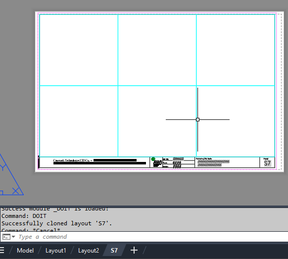
import traceback from pyrx import Ap, Db, Ed, Ge def validate_layout(source_db: Db.Database, target_db: Db.Database, layout_name: str): """Validates if the layout exists in source and is safe to write to target.""" source_layout_dict = Db.Dictionary(source_db.layoutDictionaryId()) if not source_layout_dict.has(layout_name): print(f"Layout '{layout_name}' not found in source drawing.") return False target_layout_dict = Db.Dictionary(target_db.layoutDictionaryId()) if target_layout_dict.has(layout_name): print(f"Layout '{layout_name}' already exists in target drawing.") return False return True def clone_layout_from_db(source_db: Db.Database, target_db: Db.Database, layout_name: str): """Clones a specified layout from a source database to a target database layout dictionary.""" if not validate_layout(source_db, target_db, layout_name): return False try: source_layout_dict = Db.Dictionary(source_db.layoutDictionaryId()) source_layout_id = source_layout_dict.getAt(layout_name) id_map = Db.IdMapping() id_map.setDestDb(target_db) source_db.wblockCloneObjects( [source_layout_id], target_db.layoutDictionaryId(), id_map, Db.DuplicateRecordCloning.kDrcIgnore, ) return True except Exception as e: print(f"Error encountered during cloning: {e}") traceback.print_exc() return False @Ap.Command() def doit(): layout_name = "S7" source_path = r"E:\Batch\06457 RE Submittal.dwg" target_db = Db.curDb() try: source_db = Db.Database.createFromDWG(source_path) if clone_layout_from_db(source_db, target_db, layout_name): print(f"Successfully cloned layout '{layout_name}'.") manager = Ap.LayoutManager() manager.updateLayoutTabs() except Exception as err: print(f"Failed to load or process source drawing: {err}")
1 point
-
Did the reload shx work ? It may take some time for a bug fix.1 point
-
Hello, I'm back here once again to bring up a very interesting topic: How can AutoCAD (installed on a Windows 10 tablet with an integrated GNSS receiver) be made to display its real-time UTM position (or latitude/longitude), for example through a block? Is this possible? Are there any Lisp routines capable of achieving this?1 point
-
Yep found the formula, also found some Excel convert formula. Did find even a lisp link. Try this in google. formula for convert latitude and longitude to northing and easting using lisp1 point
-
Have you tried saving, closing and reopening the drawing? I retired a few years ago and never saw the latest version. Here's a link to a lisp that will output the linetype definition of a selected line to the command line. I wrote it to extract linetypes I liked from drawings by others to add to my acad.lin file: https://forums.autodesk.com/t5/autocad-forum/export-linetype-to-acad-lin/m-p/11945136#M36909 which is why I called it LT_thief.lsp It will output the actual current linetype definition of a selected line to the command line including the shape references.1 point
-
Thanks for your interest. @BIGAL: To transform coordinates from LL to UTM, you only need to know the UTM zone, the hemisphere (N/S), and the datum (WGS84, ETRS89, Hayford, Clarke, etc.). The central meridian scale factor in the UTM system is always 0.9996. I usually work within UTM zones 31N, 32N, and 33N. However, the code should be able to return UTM coordinates for any location simply by specifying the UTM zone, hemisphere, and datum as parameters1 point
-
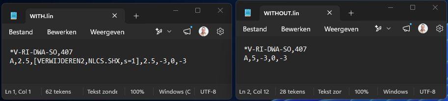
Hi All, thanks for the replies. @tombu That is exactly the issue. I removed the SHAPE reference from the linetype, reload the linetype. I see that the linetype is changed a bit, but the SHAPE keeps being shown. Even when i check the linetype definition in the DWG, the SHPAE reference is gone there, but still visualy there. Look, there are my definitions: Video attatched with my relaoding action. when i load the WITHOUT.LIN in a NEW drawing. the linetype is just fine... In the last sec off the video i do a REA command, and you see the linetype presentation change a bit. Most anoying... in AutoCAD 2023 this works just fine... looks like an AutoCAD 2027 error. Sample.mp4
1 point
-
Did you regen the drawing? Shapes are referenced by linetypes not defined by them. Whatever Shapes defined in the drawing would still be there. Did you remove the Shape references in the linetype definition before reloading it?1 point
-
I don't have AutoCAD 2027, but it may show up in AutoCAD 2026. I will do some checking when I get back to work next week. You should post your script and your shape linetypes that are an issue. You could see if a LISP works for you Lee Mac has one... https://lee-mac.com/loadlinetype.html. Here is an example of using loadlinetype.lsp in a Macro... You may want to contact Autodesk, they may know about the issue or at least would need to know.1 point
-
@GLAVCVS nicely done, yes need a convert lat long to XY, if you have CIV3D then yes can read lat long directly.1 point
-
Given that you indicate pre 2000 it is maybe time to upgrade. There is alternatives to Acad like Bricscad, Intellicad, Gstar to mention a few and much cheaper.1 point
-
@masao_8 Before i try this code, could you please explain what is does and/or provide a sample drawing to test it on? It would save me time trying to determine what you are doing. You didn't put any comments in your code explaining it. EDIT: So I tried your code and it seems to work OK for me. It appears that it adds text for circles with the dia. and copies properties from the base circle? I kind of understand what you are going for; to be able to change option (Text height) during selection. I don't have AutoCAD 2012 or AutoCAD 2016 to test what your issue is, but I think you will have to research how express tools have changed since those versions, and if the loading is different? TIP: during your window selection, you could add the filter for CIRCLES (it's already in your "_getwindowselection" function), then you wouldn't need to pick them out while processing the selection set.1 point
-
Post the extracted data we can not help unless we have something we can touch. The correct way to approach this is to match the borehole label with its corresponding attribute data. I did this for a client and we are talking hundreds of objects like your boreholes, so have something maybe already done. The simplest way is make the tables from the data.1 point
-
There is more people using Bricscad these days and designing roads, surfaces drainage and sewerage is much in demand. If Admin is happy this is a link to Civil Site Design demonstration running under Bricscad. Any one who has used CIV3D or some other CIvil software may be interested. Its features are well in advance of the current inbuilt Civil features in Bricscad. https://bricsys.registration.goldcast.io/events/6416ee0a-cbec-4869-a7fa-60922b0a5905?utm_campaign=45980519-APACWebinar-NextGenCSD-26Q3-APAC&utm_source=email&utm_medium=CADapps_email&utm_content=NextGenCSD_invite1 point
-
I don't know if I understood exactly what the need was, but here is my proposal. Moving the cursor over entities adds to the selection if the mode is active (left-click) and pressing + or - toggles to add or remove. (defun C:AutoSel ( / oldpcka key_mod ss tmp key_sel e_sel) (setq oldpcka (getvar "PICKADD") key_mod 'ssadd) (setvar "PICKADD" 2) (or (setq ss (ssget "_I")) (setq ss (ssget "_P")) ) (if ss (sssetfirst nil ss) (setq ss (ssadd))) (princ "\n[+/-]: AutoSelect ADD/REMOVE [Left-Click]: AutoSelect ON/OFF [Right-Click]: Quit AutoSelect ") (princ "\nAutoSelect <<OFF>>") (while (or (= 5 (car (setq tmp (grread t 5 2)))) (= 3 (car tmp)) (member tmp '((2 43) (2 45)))) (cond ((= 2 (car tmp)) (cond ((eq (cadr tmp) 43) (setq key_mod 'ssadd) (princ "\nMode add select") ) ((eq (cadr tmp) 45) (setq key_mod 'ssdel) (princ "\nMode remove select") ) ) ) ((= 3 (car tmp)) (if (null key_sel) (progn (setq key_sel T) (princ "\nAutoSelect <<ON>>") ) (progn (setq key_sel nil) (princ "\nAutoSelect <<OFF>>") ) ) ) ((= 5 (car tmp)) (cond ((and key_sel (setq e_sel (nentselp (cadr tmp)))) (cond ((eq 'ENAME (type (car (last e_sel)))) ((eval key_mod) (car (last e_sel)) ss) ) ((eq "VERTEX" (cdr (assoc 0 (entget (car e_sel))))) ((eval key_mod) (cdr (assoc 330 (entget (car e_sel)))) ss) ) (T ((eval key_mod) (car e_sel) ss)) ) (sssetfirst nil ss) ) (T nil) ) ) (T (princ "\nAbnormal command shutdown ")) ) ) (setvar "PICKADD" oldpcka) (princ "\nEnd of command. ") (prin1) )1 point
-
I have merged the 2 threads since they seem related.1 point
-
Admin may want to merge the two posts about this task, questions asked on other post, information is missing that is needed to provide a solution. Where is table data source ?1 point
-
Need some more clarification, you ask for multi line to be different colors, but you have table that are multi row, not Multi line cells. That is a big difference. So if you just want tables with a heading and one row to be red, then any others with header and rows greater than 2 will be heading Red line rest green 87 lines. That can be done. I think need to go back a step and work on the table creation in your other post as you pick boreholes there is no reason why the colors can not be set then. So will have a go at the other post, making single table for multiple boreholes much easier than trying to place individual tables for each borehole. Will post something for you to say yes that is ok. I did ask about the source data where is the say Excel or csv that has the values that are being used in your tables, you have supplied a half answer.1 point
-
As the cell is Mtext you can set each line a different color, using the mtext color control. This was done manually. So will see maybe later will have time to do something. Have an idea will find the cells with multi line split into multi text lines, display the line and what color it is now so you can change any or all lines. Looking at dwg it looks like you only want 2 colors 1 & 87 so will keep the multi color for later.
1 point
-
What are you trying to accomplish with this code? First and foremost vla-CopyObjects doesn't support Layouts in the manner you are attempting, AFAIK. You need to use -LAYOUT command or pretty much need to use LeeMac's Steal or at least determine the method he uses for Layouts, which if I am looking at it correctly uses the Block Table record maybe more as I quickly glanced at it.1 point
-
I've now updated this program to support resetting components of the incrementing string back to a given value with a given frequency - the latest version can be downloaded from my site: https://lee-mac.com/numinc.html1 point
-
Yes but as I have had to do things working with the government or local municipalities isn't so cut and dry. just easier to do it the way they want it1 point
-
Adding a few example macros from my Linetypes drop-down added to the Properties ribbon tab of my custom cuix file. As most of us use visual lisp it's easier to add (vl-load-com) to acaddoc.lsp than adding it to every lisp or macro. Keeping all my lin files in the same support folder as acad.lin makes accessing them easier. Loading lin files using Lee Mac's code: Reload Current ^C^C^P(or LM:LoadLinetypes (load "LoadLinetypesV1-3.lsp"))(LM:LoadLinetypes (list(getvar "celtype")) T) Reload All ^C^C^P(or LM:LoadLinetypes (load "LoadLinetypesV1-3.lsp"))(LtRedef) Dots ^C^C^P(or NewStyle (load "NewStyle.lsp"))(NewStyle "Arial" "arial.ttf") (or LM:LoadLinetypes (load "LoadLinetypesV1-3.lsp"))(LM:LoadLinetypes '("ArialDOT" "ArialDOT2" "ArialDOTX2" "PlusPlus") T) LT Curves ^C^C^P(or LM:LoadLinetypes (load "LoadLinetypesV1-3.lsp"))(LM:LoadLinetypes '("C25" "C-25" "C50" "C-50" "TREELINE_L" "TREELINE_R") T) LT Fences Walls ^C^C^P(or LM:LoadLinetypes (load "LoadLinetypesV1-3.lsp"))(LM:LoadLinetypes '("FENCELINE1" "FENCELINE2" "FENCE" "FENCE2" "FENCE5" "RD-Fence" "FENCE-BOX" "FENCE-BOX2" "FENCE-BOX4" "FENCE-BOX8" "FENCE-DIA" "FENCE-DIA2" "FENCE-DIA4" "FENCE-HW" "FENCE-H1" "FENCE-H2" "FENCE-O" "FENCE-X" "FENCE-Alan" "FENCE-X2" "FENCE-X4" "FENCE-O2" "BARBWIRE_1" "BARBWIRE_2" "CHAINLINK_1" "CHAINLINK_2" "STOCKADE_1" "STOCKADE_2" "STONEWALL") T) LT Dir Arrows ^C^C^P(or NewStyle (load "NewStyle.lsp"))(NewStyle "Arial" "arial.ttf") (or LM:LoadLinetypes (load "LoadLinetypesV1-3.lsp"))(LM:LoadLinetypes '("DIRECTION" "DIRECTION2" "DIRECTION5" "DIRECTION-A" "ArialARROW" "ArialAHead" "ArialTriangle") T) LT Danger ^C^C^P(or NewStyle (load "NewStyle.lsp"))(NewStyle "WINGDINGS" "wingding.ttf") (or LM:LoadLinetypes (load "LoadLinetypesV1-3.lsp"))(LM:LoadLinetypes '("Danger") T) Creating linetypes with text with ronjonp's lisp at https://www.theswamp.org/index.php?topic=47058.msg520876#msg520876 Everyone should have this, Thanks ronjonp! ^C^C^P(or C:makelt (load "makelt.lsp"));makelt Editing lin files: Edit Acad.lin ^C^C_start;acad.lin; Edit Arial.lin ^C^C_start;Arial.lin; Edit BOUCLES.lin ^C^C_start;BOUCLES.lin; List all Shape Names from all loaded Shape files using ShapeNames.lsp by lido. Handy if you only have the shx file not the shp. ^C^C^P(if(not ShapeNames)(load "ShapeNames.lsp"))(ShapeNames);; Code I added to bottom of Lee's LoadLinetypesV1-3.lsp for reloading all linetypes: ;Reload All Loaded Linetypes (defun LtRedef ( / acadObj doc ltlay) (setq acadObj (vlax-get-acad-object) doc (vla-get-ActiveDocument acadObj) ) (vlax-for obj (vla-get-linetypes doc) (if (not (wcmatch (vla-get-name obj) "*|*,Continuous,ByBlock,ByLayer")) (setq ltlay (cons (vla-get-name obj) ltlay)) ) ) (LM:loadlinetypes ltlay T) (vla-Regen doc acActiveViewport) ) Required lin, shx, shp and lsp files attached, adding Arial, wingdings and wingdings3 text styles are done with attached NewStyle.lsp wingdings.lin wingdings3.lin Arial.lin boucles.lin acad.lin boucles.shp boucles.shx NewStyle.lsp1 point
-
I simply would have put my new linetype (call it Propline.lin) in the same folder as the original acad.lin file was in and called it a day. Or create a new MyCustom.lin file and put all my custom lines in there never to be mixed in with the standard AutoCAD linetypes. Just curious. Did you ever run the FINDFILE command back before you mucked around in the folders to verify the correct path to acad.lin? I ran two tests. First I loaded your linetype separately, from my Desktop, in AutoCAD 2015 to check if it worked. It did. Then I edited the acad.lin file for AutoCAD 2014, started the program, loaded the linetype and it worked. Bottom line (no pun intended) you mucked things up. I'd restore the original acad.lin back where AutoCAD had it in the first place and test. If it works then make a copy (in the same folder) and edit the original acad.lin by adding your new linetype to the end of the file followed by at least one space then save. Start AutoCAD and test.1 point