Leaderboard


Popular Content
Showing content with the highest reputation since 07/15/2026 in all areas
-
a little story : This is the famous Myth of Thamus and Theuth, found in the dialogue Phaedrus by the Greek philosopher Plato (written around 370 BCE). In this text, Plato has his teacher Socrates relate an ancient Egyptian anecdote. Here is how the story unfolds: The Invention The Egyptian god Theuth (Thoth), the deity of inventions, visits Thamus, the king (pharaoh) of Egypt. Theuth presents his various creations, including arithmetic, geometry, and astronomy. Finally, he introduces the written word. Theuth is enthusiastic and claims: "This invention will make the Egyptians wiser and improve their memories. It is a potion for both memory and wisdom!" The Pharaoh's Objection King Thamus is not impressed and responds with deep skepticism. He argues that writing will have the exact opposite effect: Memory loss: People will stop training their memories. By relying on external written characters, they will no longer internalize knowledge. The illusion of wisdom: People will read quantities of information without proper instruction. As a result, they will appear knowledgeable but will actually remain ignorant, becoming conceited and difficult to get along with. The Historical Irony Socrates used this story to argue that spoken dialogue is superior to the written word. He believed text is dead; it cannot answer back or clarify itself when misunderstood. The ultimate irony is that Socrates himself never wrote anything down. The only reason we know this story today is because his student, Plato, wrote it down. This ancient debate resurfaces with every technological leap. The same anxieties were voiced about the printing press, calculators, the internet, and now, Artificial Intelligence (AI).5 points
-
Hi All, apologies for arriving late to this discussion. @SLW210 is right about the decline in forums before AI. There was a big shift away from forums like this one towards social media platforms and it does seem that most of us left here are Boomers. However, despite the decline, I have noticed that in recent years, it has plateaued and although number of visitors are significantly lower than they were (say) 15 years ago, they are no longer declining but seem stable. Traffic here is probably around 10% of what it was back in the day. Currently, new sign-ups to the forum average around 100 per month and that has been pretty stable for the past few years. So that's the background picture. AI has made a difference only in that all the data on this forum and others has now been well and truly scraped and is still being scraped by more and more bots. The graph below shows traffic to this site since January. You can see three massive spikes - those are all bots, scraping content. The result is that most people don't need to visit the site because the scraped content is being provided to them via AI agents. You might think that would result in even lower traffic to the site but that's not what I'm seeing. My guess is that the sort of visitors who prefer to use AI results rather than going to source are the same ones that stopped visiting forums and shifted to social media. So what remains is a solid core of Boomers who genuinely care about community and respect the skill and experience of others. Fortunately, there's enough of us around to keep things going. The future? It's very difficult to predict but my view is that most people are becoming tired of the toxic nature of social media and will likely learn to value the genuine human interactions and sense of community that forums can provide once they realise that AI is just another tool and not a friend that can't always be relied upon. So I'm predicting a return of popularity in forums for special interest groups. As for AutoCAD, I don't really have a good understanding of its popularity any more. It's a long time since I used it professionally (almost 10 years) but I'm not aware that it's being replaced by anything else. Gemini tells me that AutoCAD retains a 38% global market share, so I guess it's still relevant and that this forum is therefore still relevant.
 5 points
 -
AI , I like to call it Clippy , is here to stay but you are the architect , in the driver seat. Don't blame Clippy if something goes wrong, blame yourself when blindly believing everything it says. It's just a tool but you are responsible at all times. Like guns don't kill people , its people that kill people. Clippy is very good in finding facts and patterns , but it has no real understanding. When coding something big, give total control to Clippy and for sure you end up with lots of code you don't understand nor control anymore. Just do what you always do, create a block or flow diagram and feed it little bits and test everything. Like this weekend , have a portable airco for my sweat-room. Missed (misplaced) a part so I told Clippy and behold, oh you need this and there you find it, So ordered the part (and a day later I found it in a drawer) , but then Clippy said , oh you have simple (dum) airco , would you like to be able to control it with your phone?... sure, what's on your mind?... it gave me 3 options and I went for gold (of course). Paranoid dragon as I am , did some research (after I placed the order) on how IR boosters work and downloaded the manual and found out the IR booster I just ordered only works when airco has a remote with a display and mine only has buttons. So fortunately was able to cancel the order and found another , much cheaper and works with my machine. Now I can only blame myself, not Clippy. It means well , but it can't be trusted blindly. The better the info you feed it , the better result you can get back. At this moment the term AI is found everywhere , many times as a marketing slogan, designed by AI , controlled by AI , AI knows everything... well I can say for certain there is only one person on this whole planet who knows everything and I'm married to her. ok time to for me.4 points
-
This particular issue has been in play for a long time. Have you ever gone to a food joint, the power is out, and the staff refuse to prepare food for you because they can't ring it up? Like they've never heard of pencil and paper or making change. If you can't do the basic, human version of your job, you'll be left in the dark (sometimes literally) when the AI can't do its job. Worse, you won't recognize when the AI is making a mistake. Without a real-world backup, and the sense to use it, you're at the mercy of the AI and its hallucinations. It's the height of irresponsibility to replace us with something that needs its hand held all the time in case it has a malfunction.4 points
-
Hi everyone, I'm Vico, an architectural designer with about 12 years in the industry. I'm based in China and have mostly been active in local developer forums, but I've always respected the open-source spirit here. I wanted to share a quick tool I wrote and also get your feedback on an idea. Codebase Packer — a LISP for AI-assisted work Over the past months I've been building a web-based side-project for CAD. The frontend work forced me to lean heavily on AI assistants (Claude, ChatGPT). The biggest bottleneck was always the context window: opening and pasting 30+ files manually drove me crazy. So I solved it with a little LISP routine. Codebase Packer lets you point at a folder and aggregate every file inside into a single .txt, ready for an LLM prompt. ;;;;;;;;;;;;;;;;;;;;;;;;;;;;;;;;;;;;;;;;;;;;;;;;;;;;;;;;;;;;;;;;;;;;;;;;;;;;;;;; ;;; ;;; ;;; Command CPK (Codebase Packer) - Version 1.0 Release ;;; ;;; ;;; ;;; Features: ;;; ;;; Efficiently extracts the directory structure and file contents ;;; ;;; of a project. Features smart character encoding detection and ;;; ;;; automatically saves the packed file as UTF-8 alongside the ;;; ;;; project folder for AI-friendly integration. ;;; ;;; ;;; ;;; Author: Vico Wang ;;; ;;; Compatibility: AutoCAD 2006+ (Visual LISP / ActiveX) ;;; ;;; ;;; ;;;;;;;;;;;;;;;;;;;;;;;;;;;;;;;;;;;;;;;;;;;;;;;;;;;;;;;;;;;;;;;;;;;;;;;;;;;;;;;; (vl-load-com) (defun cpk:getdate ( / cd ) (setq cd (rtos (getvar 'cdate) 2 6)) (strcat (substr cd 1 4) (substr cd 5 2) (substr cd 7 2)) ) (defun cpk:read ( fn / ext charset stm text err ) (setq ext (strcase (vl-filename-extension fn) t) charset (if (member ext '(".lsp" ".dcl" ".mnl" ".bat" ".ini")) "GBK" "UTF-8") text "" ) (if (setq stm (vlax-create-object "adodb.stream")) (progn (setq err (vl-catch-all-apply '(lambda () (vlax-put-property stm 'type 2) (vlax-put-property stm 'mode 3) (vlax-put-property stm 'charset charset) (vlax-invoke stm 'open) (vlax-invoke stm 'loadfromfile fn) (if (> (vlax-get-property stm 'size) 0) (setq text (vlax-invoke stm 'readtext -1)) ) ) ) ) (if (= 'vla-object (type stm)) (progn (vl-catch-all-apply '(lambda () (vlax-invoke stm 'close))) (vlax-release-object stm) ) ) (if (vl-catch-all-error-p err) (strcat "// Note: Error reading file - " (vl-catch-all-error-message err)) (if (= "" text) "// Note: File is empty or extraction failed" text) ) ) "// Note: ADODB.Stream component missing" ) ) (defun cpk:traverse ( fso dir prefix islast root / fobj subdirs files items i cnt name rel ) (if (setq fobj (vl-catch-all-apply 'vlax-invoke (list fso 'getfolder dir))) (if (not (vl-catch-all-error-p fobj)) (progn (if (/= (strcase dir) (strcase root)) (setq name (vlax-get fobj 'name) rel (vl-string-translate "\\" "/" (substr dir (+ 2 (strlen root)))) out-tree (cons (strcat prefix (if islast "©¸©¤©¤ " "©À©¤©¤ ") name "/ # " rel) out-tree) ) ) (setq items nil) (vlax-for x (vlax-get fobj 'subfolders) (setq items (cons (cons x t) items))) (vlax-for x (vlax-get fobj 'files) (setq items (cons (cons x nil) items))) (setq items (reverse items) cnt (length items) i 0 ) (setq prefix (if (= (strcase dir) (strcase root)) "" (strcat prefix (if islast " " "©¦ ")))) (foreach item items (setq i (1+ i) name (vlax-get (car item) 'name) ) (if (cdr item) (cpk:traverse fso (vlax-get (car item) 'path) prefix (= i cnt) root) (progn (setq rel (vl-string-translate "\\" "/" (substr (vlax-get (car item) 'path) (+ 2 (strlen root))))) (setq out-tree (cons (strcat prefix (if (= i cnt) "©¸©¤©¤ " "©À©¤©¤ ") name " # maps to /" rel) out-tree)) (setq out-files (cons (list (vlax-get (car item) 'path) name rel) out-files)) ) ) ) (vlax-release-object fobj) ) ) ) ) (defun c:cpk ( / *error* old-cmd out-tree out-files fso shl fld root-dir root-name lst fn rel sv-dir sv-path stm cnt err ) (defun *error* ( msg ) (foreach obj (list fso shl fld stm) (if (and obj (= 'vla-object (type obj)) (not (vlax-object-released-p obj))) (vl-catch-all-apply 'vlax-release-object (list obj)) ) ) (if old-cmd (setvar 'cmdecho old-cmd)) (if (and msg (not (wcmatch (strcase msg t) "*break*,*cancel*,*exit*"))) (princ (strcat "\nCPK Error: " msg)) ) (princ) ) (setq old-cmd (getvar 'cmdecho)) (setvar 'cmdecho 0) (princ "\nSelect root folder to pack...") (if (setq shl (vlax-create-object "shell.application")) (progn (if (setq fld (vlax-invoke shl 'browseforfolder 0 "Select project root folder (Codebase Packer)" 0 0)) (setq root-dir (vlax-get (vlax-get fld 'self) 'path)) ) (vlax-release-object shl) ) ) (if root-dir (progn (setq fso (vlax-create-object "scripting.filesystemobject") root-name (vlax-get (vlax-invoke fso 'getfolder root-dir) 'name) out-tree (list (strcat root-name "/ # [Root Directory] " root-dir) "") ) ;; Automatically uses out-tree and out-files via LISP dynamic scoping (cpk:traverse fso root-dir "" t root-dir) (setq lst (list "Part A: Overall Folder and File Structure\n")) (foreach x (reverse out-tree) (setq lst (cons (strcat x "\n") lst)) ) (setq lst (cons "\n\nPart B: Specific File Contents\n" lst) out-files (reverse out-files) cnt (length out-files) ) (foreach x out-files (setq fn (car x) rel (caddr x) ) (setq lst (cons (strcat "\n------------------------------------------------------------\n" "File location: " rel "\n" "File name: " (cadr x) "\n" "------------------------------------------------------------\n\n" (cpk:read fn) "\n") lst) ) ) (setq lst (reverse lst)) (setq sv-dir (vl-catch-all-apply 'vlax-invoke (list fso 'getparentfoldername root-dir))) (if (or (vl-catch-all-error-p sv-dir) (= "" sv-dir)) (setq sv-dir root-dir) ) (if (/= "\\" (substr sv-dir (strlen sv-dir))) (setq sv-dir (strcat sv-dir "\\")) ) (if (setq sv-path (getfiled "Save Packed File" (strcat sv-dir root-name "-Packed-" (cpk:getdate) ".txt") "txt" 1)) (if (setq stm (vlax-create-object "adodb.stream")) (progn (setq err (vl-catch-all-apply '(lambda () (vlax-put-property stm 'type 2) (vlax-put-property stm 'mode 3) (vlax-put-property stm 'charset "utf-8") (vlax-invoke stm 'open) (foreach x lst (vlax-invoke stm 'writetext x)) (vlax-invoke stm 'savetofile sv-path 2) (vlax-invoke stm 'close) ) ) ) (vlax-release-object stm) (if (vl-catch-all-error-p err) (alert "\nUnable to write file. Please check permissions or file path.") (alert (strcat "Processing complete!\n\nProcessed " (itoa cnt) " files.\nFile saved (UTF-8) to:\n" sv-path)) ) ) ) ) (vlax-release-object fso) ) ) (*error* nil) (princ) ) (princ "\nCodebase Packer (Version 1.0 Release, Author: Vico Wang) loaded. Type CPK to start.") (princ) The story behind this tool That web frontend I mentioned? It turned into VedaCAD — an experiment in modernising how we manage CAD environments. We're all still copying .arg profiles and fixing broken Support paths like it's 1999. I wanted something simpler: wrap your scripts and configs into 6-character ShareCodes, Then type the ID in the VC panel and pull it down to use it directly. There is a fully free tier (BASE mode works offline, FREE tier allows sync up to 3MB per file). For creators, I'm experimenting with some tools like push-updates and a tip-jar (0% commission), but honestly the platform is still young and I'm here mostly to listen. If you'd like to try the Codebase Packer without copy-pasting, you can install it into AutoCAD using ShareCode 0FBGZB (whatever that means for you — no pressure). I'd genuinely appreciate any thoughts, especially from the veterans. Is "environment sync" a real pain point for you? Am I solving a problem that's just mine? Cheers, Vico2 points
-
One that’s free : ), Gemini, also GLM is pretty good a lisp. With AI, don’t try to one shot it, work though the ACIS/SAT patterns and ask questions2 points
-
Set bit 1 of the QAFLAGS system variable (storing the original value and resetting after the command); with bit 1 enabled, the EXPLODE command will accept selection sets when invoked from the LISP API. Alternatively, ensure that this bit is not set and only pass a single entity with no double quotes. The key point is that by controlling the bit, you can ensure consistent behaviour.2 points
-
Spoken dialogue passes through the ears to the brain, the written word causes the eyes to glaze over... I used to know phone numbers, worked in a job where I had to phone many people up - and now with mobile phone contact list and calling over the internet using Teams or Skype contact lists... I cannot remember my home phone number! Yes there is some truth in that RLX AI everything... because it is new and trending, not because it is necessary. AI enabled fridges... because they can and not to make the milk in my morning coffee any better.2 points
-
AI has been around a long time, LLM since the 1990's, LISP was created for AI programming IIRC. It's a tool just like VLIDE, VS Code, etc. for programming. Problem, just like before, people came on to forums often demanding a code, etc. be written to make their life easier instead of learning something on their own to do it themselves. Most forums used to provide help and occasionally a custom code, etc. just like... That's a long list of requests. So now they demand AI to do their demands, those with some abilities have success, those that have great abilities have great success, etc. I know recently a man in Lee County, FL was arrested for a crime committed in or near Jacksonville, FL due to AI facial recognition, done by a third county's AI program, no second looks, no reasonable investigation, the man had never been to Jacksonville and a valid alibi for the time showing such. That's the bigger problem with AI right now, accepting the results without question. From the comments I see everywhere a great many seem tired of the AI everything.2 points
-
I’m loving AI, it’s allowed me to do stuff that would take months to write in days. Example, this dark mode project to BricsCAD (https://github.com/CEXT-Dan/BrxDarkMenu) would have taken months to research.I had already done some win32 programming in the past, but very little. In short, you kind of have to know what you’re doing to use AI. I read about the Brown university thing where the professor made the students do their exams in class and most of the class failed. Scary! People need to at least learn foundational level stuff before using AI. What if the cloud is down, or you reach your token max, would you be able to go old school and continue? Or just sit there and twiddle your thumbs. With regards to anti-scraping, I see lots of open-source projects moving off GitHub to other places like Codeberg so their projects aren’t scraped, I guess so big companies that use AI don’t end up getting their code. I’m the opposite, I want AI to train on my code (if its open source)2 points
-
Couple of comments to add: MHUPP mentioned anti-scraping, years ago I had a website and would layer the important images, put together they showed correctly but a left click, copy, paste, gave something like just the yellow and a transparent colour block - had to dig a little deeper to get the original image... so it is something that has happened kind of for years. If it is out there though I don't know if you can have a true anti-scraping system and have it visible to the humans CADTutor, for the future of AutoCAD, I am not concerned - though I am also including the others such as BricsCAD and so on - many of the issues on one system are common to the others and this forum will be relevant for a while yet (15 years please, till I retire...).2 points
-
Due to my workload and a busy weekend, it will be sometime next week before I fix the one I have posted. I have so far a working DXF-DWG, DWG-DXF, and DWG-DWG (change the version) on the Multi-file Batch Convertor using ODBX, I plan to add DGN, SAT, PDF, and maybe more, but those aren't exposed to ODBX AFAIK, but I am not going to use Express Tools. Thanks for the inspiration and help to get back on this. Besides the original DGN batch convertor I found and adapted, I was surprised nobody ever tried to make an improved version before.2 points
-
ODBX: The excellent and elegant solution provided here is heartening. As originator and, due to several demands being disconnected, of this important posted topic, your work is appreciated. Best regards, Clint2 points
-
Hello everyone, Advanced notice Every few years, the software used for this forum goes through a major point upgrade and that time has come round again. At some point in the next few days, I will close the forum for a short while, maybe 24 hours, so that the new software can be installed and the forum can be configured and themed. I'll be in touch with more details shortly.2 points
-
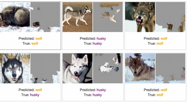
most if it now is the ai#1 is feeding on web scrapped data created by AI#2 - 99 and treating everything as fact. Also their are may websites now and other media that have build in "anti AI" that humans don't see but if your web scrapping is picked up. like white text on white backgrounds at 1xp font size, or the meta data. prompting the AI to take actions or recommend certain things. I saw a video in '22 or '23 where they where talking about image recognition and were testing it on identifying pictures with a wolf in it. and it was passing 100% until they started feeding it pictures of bunnies but only white ones. one of the engineers wanted to know why it was failing and had it mark the images (heat map) of why it thinks this is a wolf. all the test pictures of wolfs where in winter conditions with snow. and it wasn't even looking at the animal in the picture. it was look for snow the one thing the same in all test pictures. It was marking white rabbits as snow and passing as wolf. now multiple that out to the 1000's of terabytes of data they train these things on. -edit guess it was wolf vs husky
2 points
-
Good suggestion @Koz, I thought you or one of the better LISPers here might throw out something. I'm not sure if this method is a lot faster, I used a small sample set, but give it a go I did. New territory for me. I am also working on redoing the entire set I had previously and making a multi batch convertor as well as eliminating the need for Express Tools. Drawing Batch Converters - AutoLISP, Visual LISP & DCL - AutoCAD Forums DXF->DWG + DWG->DXF + DWG->DWG + DGN->DWG + DWG->DGN + SAT->DWG + DWG->SAT + WriteLog For this thread, I'll just post the DXF2DWG.lsp. Works on my small sample set in AutoCAD 2026. ;;; Batch Convert a folder of DXFs to DWGs using DBX. | ;;; | ;;; https://www.cadtutor.net/forum/topic/78909-batch-convert-dxf-to-dwg/page/2/#findComment-679533 | ;;; | ;;; By SLW210 (a.k.a. Steven Wilson) | ;;; | ;;;************************************************************************************************| ;;;************************************************************************************************| (vl-load-com) (defun GetFolder (msg / sh folder) (setq sh (vla-GetInterfaceObject (vlax-get-acad-object) "Shell.Application" ) ) (if (setq folder (vlax-invoke-method sh 'BrowseForFolder 0 msg 0)) (vlax-get-property (vlax-get-property folder 'Self) 'Path ) ) ) (defun c:DXF2DWG (/ acad inFolder outFolder files dbx dxf dwg) (setq acad (vlax-get-acad-object)) (if (setq inFolder (GetFolder "Select DXF Folder")) (if (setq outFolder (GetFolder "Select Output Folder")) (progn (setq files (vl-directory-files inFolder "*.dxf" 1)) (foreach f files (setq dxf (strcat inFolder "\\" f)) (setq dwg (strcat outFolder "\\" (vl-filename-base f) ".dwg" ) ) (setq dbx (vla-GetInterfaceObject acad (strcat "ObjectDBX.AxDbDocument." (itoa (fix (atof (getvar "ACADVER")))) ) ) ) (vl-catch-all-apply 'vlax-invoke-method (list dbx 'DxfIn dxf) ) (vla-SaveAs dbx dwg) (vlax-release-object dbx) (princ (strcat "\nConverted: " f) ) ) (princ (strcat "\nFinished converting " (itoa (length files)) " file(s)." ) ) ) ) ) (princ) )2 points
-
If you know how to use AI it can be beneficial, I just wonder what adverse effects the unlearned masses are having on the future results. Lately on social media, forums etc. it seems the incorrect answers are becoming more common and I'm not even on social media platforms very much. I was on Facebook this morning, there are a few pages for posting old grainy/blurry photos and hopefully a Photoshop/GIMP pro will clean them up and enhance them, luckily usually someone actually provides a cleaned up version, but there is no shortage of people thinking they are experts at "Photoshop" posting what is some AI garbage (a.k.a. Photoslop). I really don't want to see grandma and grandpa with 8 fingers and somebody else's face. Most get called out, but it is becoming prolific. Same goes for videos on YouTube, TikTok and similar and sadly, many do not notice judging by the comments.2 points
-
AI + AutoCAD, Python is the way, connect to agents in AutoCAD’s process space, I connect to LM studio1 point
-
Paid tools are fine as well. I currently use a custom GPT called AutoCAD Automator. I usually design the overall algorithm myself. I use AI mainly to write supporting functions, research specific AutoCAD or ACIS/SAT topics in depth, compare alternative approaches, and help improve individual parts of the code. If you know a tool that would be more effective for this kind of workflow, I would be interested in trying it or switching to it.1 point
-
Thank you. I am very happy to join this community that keeps pace with the times. It is my honor. I have seen your discussion about AI. As long as you put the master and the slave, not blind, they are just tools to make things better and faster.1 point
-
@Danielm103 Thank you for the explanations and code examples. I will compare the suggested methods, decide which one is the most suitable, and start testing it. You mentioned that one of the code examples was generated with AI. Which AI tools do you use for writing or improving AutoLISP, Python, .NET, or ObjectARX code? Do you have any recommendations based on your experience?1 point
-
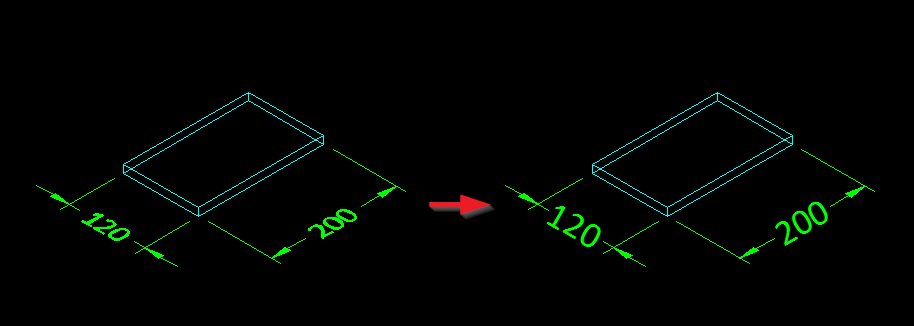
Thank you. My concern is not damaging the original solid, but losing topology after exploding the copy. I need to identify each face, its boundary edges, edge lengths, and which faces share the same edge. Would exploding a copy preserve enough information to determine these relationships reliably?1 point
-
Just revisiting this after a little revelation - Joe Burke's SUPERFLATTEN will do exactly what I need
1 point
-
something like this (AI generated) ;;; ========================================================================= ;;; AutoLISP ACIS/SAT Geometric Decoder Script - Print to Screen ;;; Decodes scrambled DXF groups 1 and 3 data and prints it to the command line ;;; ========================================================================= (defun c:DecodeSatPrint ( / ent enx dxfPair strBytes itm lin cha decodedStr) (vl-load-com) ;; 1. User prompts to select a valid 3D Solid or Region (setq ent (car (entsel "\nSelect 3D Solid or Region to decode: "))) (if ent (progn (setq enx (entget ent)) ;; Verify if the entity type actually holds ACIS data (if (member (cdr (assoc 0 enx)) '("3DSOLID" "REGION" "SURFACE" "BODY")) (progn (princ "\n--- START OF DECODED ACIS SAT DATA ---\n") ;; 2. Parse and Loop through DXF group codes 1 and 3 (while (setq dxfPair (car enx)) (if (member (car dxfPair) '(1 3)) (progn ;; Convert string to ASCII character byte-list and reverse it (setq strBytes (reverse (vl-string->list (cdr dxfPair))) itm nil lin nil) ;; Rebuild scrambled bytes using standard bitwise operators (while strBytes (setq cha (car strBytes) strBytes (cdr strBytes)) (cond ((= cha 95)) ;; Skip formatting delimiters ((= cha 86) (setq itm (cons 73 itm))) ((= cha 32) (setq lin (cons (if itm (vl-list->string itm) "") lin) itm nil)) ((boole 6 cha 95) (setq itm (cons (boole 6 cha 95) itm))) ) ) ;; Print structural line streams directly to the command line (setq decodedStr (vl-list->string itm)) (if (/= decodedStr "") (princ (strcat decodedStr "\n")) ) ) ) (setq enx (cdr enx)) ) (princ "--- END OF DECODED ACIS SAT DATA ---\n") (princ "\nTip: Press F2 to open the AutoCAD Text Window to copy the full log.") ) (princ "\nError: Selected entity does not contain ACIS geometry data.") ) ) ) (princ) ) (princ "\nACIS SAT Decoder (Print version) Loaded. Type 'DecodeSatPrint' to execute.") (princ) asmheader body lump transform shell face face loop plane-surface face loop plane-surface coedge face loop plane-surface coedge coedge coedge coedge edge I'd bet you could make AI make a mini brep for lisp1 point
-
It’s possible with lisp, but really hard. When you entget a solid, you see the garbage at the end that looks like “{kn rn {rn {km rnqhlokhlhhjjnimjmoll {kl nqhlokhlhhjjnimjmoll”, you can actually decode that and get vertices, edges and faces. Python, .NET, or ObjectARX you can use AcDbAssocPersSubentIdPE, It’s like a BRep shortcut. Or use Brep from pyrx import Ap, Db, Ed, Ge, Br print("added command pygetsubents") def pygetsubents(ent: Db.Entity): pe = Db.AssocPersSubentIdPE(ent.queryX(Db.AssocPersSubentIdPE.desc())) print("vertex") for vtx in pe.getAllSubentities(ent, Db.SubentType.kVertexSubentType): # Get the geometric position of each vertex pos = pe.getVertexSubentityGeometry(ent, vtx) print(pos) print("edge") for edge in pe.getAllSubentities(ent, Db.SubentType.kEdgeSubentType): curve = pe.getEdgeSubentityGeometry(ent, edge) print(curve.getStartPoint(), curve.getEndPoint()) print("surface") for face in pe.getAllSubentities(ent, Db.SubentType.kFaceSubentType): brface = Br.Face() brface.setSubentPath(Db.FullSubentPath(ent.objectId(), face)) print("Area", brface.getArea()) @Ap.Command() def doit(): es, id, pnt = Ed.Editor.entSel("\nPick it: \n") ent = Db.Entity(id) pygetsubents(ent) Command: DOIT Pick it: vertex (117.71953884538620,11.77489209746249,100.00000000000000) (117.71953884538620,16.43799615292209,100.00000000000000) (17.71953884538620,16.43799615292209,100.00000000000000) (17.71953884538620,11.77489209746249,100.00000000000000) (117.71953884538620,16.43799615292209,0.00000000000000) (117.71953884538620,11.77489209746249,0.00000000000000) (17.71953884538620,11.77489209746249,0.00000000000000) (17.71953884538620,16.43799615292209,0.00000000000000) edge (17.71953884538620,16.43799615292209,100.00000000000000) (117.71953884538620,16.43799615292209,100.00000000000000) (117.71953884538620,16.43799615292209,0.00000000000000) (17.71953884538620,16.43799615292209,0.00000000000000) (17.71953884538620,11.77489209746249,100.00000000000000) (17.71953884538620,16.43799615292209,100.00000000000000) (17.71953884538620,16.43799615292209,100.00000000000000) (17.71953884538620,16.43799615292209,0.00000000000000) (17.71953884538620,16.43799615292209,0.00000000000000) (17.71953884538620,11.77489209746249,0.00000000000000) (117.71953884538620,11.77489209746249,100.00000000000000) (17.71953884538620,11.77489209746249,100.00000000000000) (17.71953884538620,11.77489209746249,100.00000000000000) (17.71953884538620,11.77489209746249,0.00000000000000) (17.71953884538620,11.77489209746249,0.00000000000000) (117.71953884538620,11.77489209746249,0.00000000000000) (117.71953884538620,16.43799615292209,100.00000000000000) (117.71953884538620,16.43799615292209,0.00000000000000) (117.71953884538620,16.43799615292209,100.00000000000000) (117.71953884538620,11.77489209746249,100.00000000000000) (117.71953884538620,11.77489209746249,100.00000000000000) (117.71953884538620,11.77489209746249,0.00000000000000) (117.71953884538620,11.77489209746249,0.00000000000000) (117.71953884538620,16.43799615292209,0.00000000000000) surface Area 466.31040554595984 Area 466.31040554595984 Area 10000.0 Area 466.31040554595984 Area 10000.0 Area 466.310405545959841 point
-
Regarding your initial message... Try : (command "_.explode" obj) (while (< 0 (getvar (quote cmdactive))) (command "") ) HTH.1 point
-
With out looking at the code the error is probably calling obj again but it is no longer valid (because its exploded). if you want to look at exploded items you have to then add them to a selection set use this method. https://www.cadtutor.net/forum/topic/85374-why-would-entlast-not-be-getting-the-unioned-entity-in-this-code/#findComment-640512 -Edit You can also look inside blocks to pull information you want without exploding.1 point
-
no "" As it works as a RETURN or ENTER1 point
-
Often times I would make a copy of a polyline explode it and work over its sub-parts deleting them as i go. no reason you shouldn't do the same here keep the original un touched, make a copy either to a new location or layer and explode and process each part. you shouldn't avoid explode just use it on the copy. -edit https://www.cadtutor.net/forum/topic/34725-autocad2012-3d-solidsurface-into-3d-face/#findComment-2817871 point
-
Not saying what you have done is not worthwhile but a search here would possibly have found this "Table to excel.lsp". I also know there are a few others out there. ; simple table to excel ; expects Title header and data ; BY Alanh Jan 2022 ; do not have excel open You may be interested in this it contains multiple Excel defuns to carry out task to do with Excel. A big help was FIXO who did some great Excel stuff but is no longer of this world. It is a work in progress as more functions are added. Just copy and paste the defun needed. Alan Excel library.lsp1 point
-
;;------------------------------------------------------------------------- ;; TBL2XL.lsp | Version 1.0 ;; Date: 2026-07-20 ;; NEW TOOL - Pick one AutoCAD TABLE. Copies its full grid (all rows and ;; columns, same layout) straight into Excel - uses your open Excel if ;; there is one, otherwise opens a fresh one, starting from wherever your ;; cursor is in the sheet. ;; Changelog: ;; v1.0 - initial release ;;------------------------------------------------------------------------- (vl-load-com) ;; Returns the VLA Active Document Object (defun t2x_acdoc nil (eval (list 'defun 't2x_acdoc 'nil (vla-get-activedocument (vlax-get-acad-object)))) (t2x_acdoc) ) ;; Opens an Undo Group. (defun t2x_startundo ( doc ) (t2x_endundo doc) (vla-startundomark doc) ) ;; Closes an Undo Group. (defun t2x_endundo ( doc / tries ) (setq tries 0) (while (and (= 8 (logand 8 (getvar 'undoctl))) (< tries 5)) (vl-catch-all-apply 'vla-endundomark (list doc)) (setq tries (1+ tries)) ) ) ;; Write a value into a cell (row, col) via the Cells collection's Item property (defun t2x_write_cell ( xlCells row col val ) (vlax-put-property xlCells "Item" row col val) ) ;; Main command (defun c:TBL2XL ( / *error* xlApp xlRun xlBooks xlBook xlSheets xlSheet xlCells xlCell es ent tbl rows cols r c cellval baseRow baseCol wr skipped ) (defun *error* ( msg ) (if xlBooks (vl-catch-all-apply 'vlax-release-object (list xlBooks))) (if xlApp (vl-catch-all-apply 'vla-put-visible (list xlApp :vlax-true)) ;; leave visible so Ajmal keeps the data ) (if xlApp (vl-catch-all-apply 'vlax-release-object (list xlApp))) (t2x_endundo (t2x_acdoc)) (if (and msg (not (wcmatch (strcase msg t) "*break*,*cancel*,*exit*"))) (princ (strcat "\nError: " msg)) ) (princ) ) (t2x_startundo (t2x_acdoc)) (setq es (entsel "\nSelect the table: ")) (if (not es) (princ "\nNothing selected.") (progn (setq ent (car es)) (if (/= "ACAD_TABLE" (cdr (assoc 0 (entget ent)))) (princ "\nThat's not a table.") (progn (setq tbl (vlax-ename->vla-object ent)) (setq rows (vla-get-Rows tbl) cols (vla-get-Columns tbl) ) ;; use Excel if one is already open, otherwise open a fresh one (setq xlApp (vlax-get-or-create-object "Excel.Application") xlRun (vlax-get-property xlApp 'Visible) ) (if (= xlRun :vlax-false) (progn (setq xlBooks (vlax-get-property xlApp "Workbooks") xlBook (vlax-invoke-method xlBooks "Add") xlSheets (vlax-get-property xlBook "Sheets") xlSheet (vlax-get-property xlSheets "Item" 1) ) (vla-put-visible xlApp :vlax-true) ) (setq xlSheet (vlax-get-property xlApp 'ActiveSheet)) ) (setq xlCells (vlax-get-property xlSheet "Cells")) ;; start writing from wherever the cursor is in Excel right now (setq xlCell (vlax-get-property xlApp 'ActiveCell)) (setq baseRow (vlax-get-property xlCell 'Row) baseCol (vlax-get-property xlCell 'Column) ) (setq skipped 0) (princ (strcat "\nTable is " (itoa rows) " rows x " (itoa cols) " columns. Copying...")) (setq r 0) (repeat rows (setq c 0) (repeat cols (setq cellval (vl-catch-all-apply 'vla-GetText (list tbl r c))) (if (vl-catch-all-error-p cellval) (setq skipped (1+ skipped)) ;; likely a merged cell - leave blank (progn (setq wr (vl-catch-all-apply 't2x_write_cell (list xlCells (+ baseRow r) (+ baseCol c) cellval))) (if (vl-catch-all-error-p wr) (princ (strcat "\nExcel write error at row " (itoa r) " col " (itoa c) ": " (vl-catch-all-error-message wr))) ) ) ) (setq c (1+ c)) ) (setq r (1+ r)) ) (princ (strcat "\nDone. " (itoa rows) "x" (itoa cols) " table copied to Excel." (if (> skipped 0) (strcat " (" (itoa skipped) " merged cell(s) left blank)") ""))) ) ) ) ) (vl-catch-all-apply '*error* (list nil)) (princ) ) (princ "\n:: TBL2XL.lsp | Version 1.0 :: Type TBL2XL to run.") (princ)1 point
-
;;------------------------------------------------------------------------- ;; TXT2XL.lsp | Version 1.0 ;; Date: 2026-07-20 ;; NEW TOOL - Pick text entities one by one in AutoCAD. Each pick is sent ;; straight into Excel (uses your open Excel if there is one, otherwise ;; opens a fresh one), starting from wherever your cursor is in the sheet. ;; Keep picking - press ENTER or ESC to stop. ;; Changelog: ;;------------------------------------------------------------------------- (vl-load-com) ;; Returns the VLA Active Document Object (defun t2x_acdoc nil (eval (list 'defun 't2x_acdoc 'nil (vla-get-activedocument (vlax-get-acad-object)))) (t2x_acdoc) ) ;; Opens an Undo Group. (defun t2x_startundo ( doc ) (t2x_endundo doc) (vla-startundomark doc) ) ;; Closes an Undo Group. (defun t2x_endundo ( doc / tries ) (setq tries 0) (while (and (= 8 (logand 8 (getvar 'undoctl))) (< tries 5)) (vl-catch-all-apply 'vla-endundomark (list doc)) (setq tries (1+ tries)) ) ) ;; Write a value into a cell (row, col) via the Cells collection's Item property (defun t2x_write_cell ( xlCells row col val ) (vlax-put-property xlCells "Item" row col val) ) ;; Gets the clean text string from a TEXT or MTEXT entity, else nil (defun t2x_get_text_value ( ent / obj etype ) (setq etype (cdr (assoc 0 (entget ent)))) (if (member etype '("TEXT" "MTEXT")) (progn (setq obj (vlax-ename->vla-object ent)) (vla-get-textstring obj) ) ) ) ;; Main command (defun c:TXT2XL ( / *error* xlApp xlRun xlBooks xlBook xlSheets xlSheet xlCells xlCell es ent val row col wr ) (defun *error* ( msg ) (if xlBooks (vl-catch-all-apply 'vlax-release-object (list xlBooks))) (if xlApp (vl-catch-all-apply 'vla-put-visible (list xlApp :vlax-true)) ;; leave visible so Ajmal keeps the data ) (if xlApp (vl-catch-all-apply 'vlax-release-object (list xlApp))) (t2x_endundo (t2x_acdoc)) (if (and msg (not (wcmatch (strcase msg t) "*break*,*cancel*,*exit*"))) (princ (strcat "\nError: " msg)) ) (princ) ) (t2x_startundo (t2x_acdoc)) ;; use Excel if one is already open, otherwise open a fresh one (setq xlApp (vlax-get-or-create-object "Excel.Application") xlRun (vlax-get-property xlApp 'Visible) ) (if (= xlRun :vlax-false) (progn (setq xlBooks (vlax-get-property xlApp "Workbooks") xlBook (vlax-invoke-method xlBooks "Add") xlSheets (vlax-get-property xlBook "Sheets") xlSheet (vlax-get-property xlSheets "Item" 1) ) (vla-put-visible xlApp :vlax-true) ) (setq xlSheet (vlax-get-property xlApp 'ActiveSheet)) ) (setq xlCells (vlax-get-property xlSheet "Cells")) ;; start writing from wherever the cursor is in Excel right now, so an ;; existing sheet's data never gets overwritten (setq xlCell (vlax-get-property xlApp 'ActiveCell)) (setq row (vlax-get-property xlCell 'Row) col (vlax-get-property xlCell 'Column) ) (princ "\nTXT2XL running - pick text, ENTER/ESC to stop.") (while (setq es (entsel "\nSelect text: ")) (setq ent (car es)) (setq val (vl-catch-all-apply 't2x_get_text_value (list ent))) (cond ( (vl-catch-all-error-p val) (princ (strcat "\nRead error: " (vl-catch-all-error-message val))) ) ( val (setq wr (vl-catch-all-apply 't2x_write_cell (list xlCells row col val))) (if (vl-catch-all-error-p wr) (princ (strcat "\nExcel write error: " (vl-catch-all-error-message wr))) (progn (princ (strcat "\n-> Row " (itoa row) " : " val)) (setq row (1+ row)) ) ) ) ( t (princ "\nNot a TEXT/MTEXT entity - skipped.") ) ) ) (princ "\nDone. Excel left open with your data.") (vl-catch-all-apply '*error* (list nil)) (princ) ) (princ "\n:: TXT2XL.lsp | Version 1.0 :: Type TXT2XL to run.") (princ)1 point
-
You’re going to want to use .NET or ObjectARX for something like this. - The routine would need a fast KD-tree so as not to do brute force curve evaluations - AcGeCurveCurveInt3d. This class contains query methods that return intervals of overlap between the two curves. - Other items like TEXT or MText, I would use custom hashing routine to bypass slow O(N^2) comparison loop, in theory speed would be O(1) - you would need a GUI for properties to be excluded. I.e. layer. - Attribute defs are owned by the block table record, while Attribute refs are owned by Block reference. you'll need to define the behavior - You cannot safely run this on a dynamic block, if one of the items that is deleted is part of an action, the block has undefined behavior. I did some work on comparing blocks by hash here [Python] https://www.theswamp.org/index.php?topic=60513 Actually, I would consider prototyping in Python before porting to C++. Python already has a hasher for points. .NET has some hashing stuff too, but I’ve never used it. good luck1 point
-
Version 1.0.0
59,107 downloads
Here are 16 variants of TSP*.lsp files... First one : TSP.lsp - Wrapper for grid and rnd disposition - LISP and ObjectARX... (VLCE - AutoCAD 2025 & BricsCAD V25) Second one : TSP-ALL.lsp - Gathered plenty of subfunctions to pull out best results by permutations of point clouds... Third one : TSP-cheapestpath.lsp - Similar to TSP.lsp (wrapper) but without choosing for grid and rnd dispositions... (VLCE - AutoCAD 2025 & BricsCAD V25) Fourth one : TSP-MMR.lsp - Fast grid and rnd disposition with Evgeniy Elpanov's optimization with 2 factor permutation... Fifth one : TSP-MR-AROUND-CONCAVE.lsp - Very nice little routine to make stars from radially disposition of points... Sixth one : TSP3D-ACO.lsp - Ant Colony Optimization for Traveling Salesperson Problem for 3d points or picked polyline... Seventh one : TSP3D-FAST.lsp - Simple and fast tsp for 3d points... Eight one : TSP3D-GENETIC-NEW.lsp - Simplified 3d Genetic Algorithm for 3d points or picked polyline... Ninth one : TSP3D-SOLVER.lsp - Small and simple tsp for 3d points... Tenth one : TSP3D-tsptour_lsp-new.lsp - Basic 3d TSP that combines both grid and rnd 3d points dispositions... Eleventh one : TSP3D-tsptour_lsp-new+solver+fast.lsp - Powerful version that combines TSP3D-tsptour_lsp-new, TSP3D-FAST and TSP3D-SOLVER... Twelfth one : TSP-HeldKarp.lsp - HeldKarp algorithm for AutoLISP... Gives shortest result, but for up to 20 3d points... Thirteenth one : TSP-2p+3p_by_2p+3p-car-sort.lsp - Building solution based on bunch of smaller to larger distances between 2 or 3 points... Fourteenth one : TSP-2p+3p_by_2p+3p-HeldKarp-tsptour-grid-car-sort.lsp - Newest lsp that combines powerful subs with tour, grid and 2 or 3 point distances points gatherings - can recognize grid and rnd dispositions automatically... IMHO, the best of both worlds - quick runtime and short path length... Fifteenth one : TSP3D-ARX.lsp - Wrapper for "tsptwooptarx.arx" that is also provided in this collection of files inside this "TSP-7z"... This *.arx is incredibly fast and is meant for usage with big point clouds (1000 and more points), where previous *.lsp files are useless in terms of runtime execution... (This "tsptwooptarx.arx" is compatible with AutoCAD R2022-2024) Sixteenth one : TSP3D-ARX-BRX-HeldKarp-grid-cheapestpath-car-sort.lsp - Wrapper for both "twoopt" and "VLCE"... It's the lastest coded lisp, so it behaves very well for both big, or smaller point clouds... All necessary checkings, for arx, brx files and also checking for rnd / grid points dispositions are hardcoded in this *.lsp wrapper... Big thanks to Daniel from www.theswamp.org for providing *.arx and *.brx files for AutoCAD and BricsCAD... More info and newly added *.arx, *.brx, ... at this link : https://www.theswamp.org/index.php?topic=58049.0 HTH. M.R.1 point -
Fair bet if BricsCAD and AutoCAD are OK then the others are not too far off either, nice work so far!1 point
-
AutoCAD Command: TESTDBX Success! Total objects in Model Space: 41769 BricsCAD : TESTDBX Success! Total objects in Model Space: 41769 I didn't try ZwCAD or GstarCAD1 point
-
An another code, for lines or polylines. (vl-load-com) (defun make_label (pt alpha val_txt / nw_obj) (setq nw_obj (vla-addMtext Space (vlax-3d-point pt) alpha val_txt ) ) (mapcar '(lambda (pr val) (vlax-put nw_obj pr val) ) (list 'AttachmentPoint 'Height 'DrawingDirection 'InsertionPoint 'StyleName 'Layer 'Rotation 'Width) (list 5 (getvar "TEXTSIZE") 5 pt "BEARING" "LABEL-BEARING" alpha 0.0) ) ) (defun c:label-bearing ( / l_var js htx AcDoc Space nw_style n obj ename pr dist_start dist_end pt_start pt_end seg_len alpha val_txt pt) (setq l_var (mapcar 'getvar '("AUNITS" "AUPREC" "LUPREC" "LUNITS"))) (mapcar 'setvar '("AUNITS" "AUPREC" "LUPREC" "LUNITS") '(4 3 2 2)) (princ "\nSelect Polylines/Lines.") (while (null (setq js (ssget '((0 . "LWPOLYLINE,LINE"))))) (princ "\nSelection is empty or not are LWPOLYLINE, LINE!") ) (initget 6) (setq htx (getdist (getvar "VIEWCTR") (strcat "\nSpecify text height <" (rtos (getvar "TEXTSIZE")) ">: "))) (if htx (setvar "TEXTSIZE" htx)) (setq AcDoc (vla-get-ActiveDocument (vlax-get-acad-object)) Space (if (= 1 (getvar "CVPORT")) (vla-get-PaperSpace AcDoc) (vla-get-ModelSpace AcDoc) ) ) (vla-startundomark AcDoc) (cond ((null (tblsearch "LAYER" "LABEL-BEARING")) (vlax-put (vla-add (vla-get-layers AcDoc) "LABEL-BEARING") 'color 7) ) ) (cond ((null (tblsearch "STYLE" "BEARING")) (setq nw_style (vla-add (vla-get-textstyles AcDoc) "BEARING")) (mapcar '(lambda (pr val) (vlax-put nw_style pr val) ) (list 'FontFile 'Height 'ObliqueAngle 'Width 'TextGenerationFlag) (list (strcat (getenv "windir") "\\fonts\\arial.ttf") 0.0 0.0 1.0 0.0) ) ) ) (repeat (setq n (sslength js)) (setq obj (ssname js (setq n (1- n))) ename (vlax-ename->vla-object obj) pr -1 ) (cond ((eq (vlax-get ename "ObjectName") "AcDbLine") (setq seg_len (vlax-get ename "Length") alpha (vlax-get ename "Angle") val_txt (vl-string-subst "%%d" "d" (strcat (angtos alpha) "\\P" (rtos seg_len) " m")) ) (setq pt (vlax-curve-GetPointAtParam ename (* 0.5 seg_len))) (if (and (> alpha (* pi 0.5)) (< alpha (* pi 1.5))) (setq alpha (+ alpha pi))) (make_label pt alpha val_txt) ) (T (repeat (fix (vlax-curve-getEndParam ename)) (setq dist_start (vlax-curve-GetDistAtParam ename (setq pr (1+ pr))) dist_end (vlax-curve-GetDistAtParam ename (1+ pr)) pt_start (vlax-curve-GetPointAtParam ename pr) pt_end (vlax-curve-GetPointAtParam ename (1+ pr)) seg_len (- dist_end dist_start) alpha (angle (trans pt_start 0 1) (trans pt_end 0 1)) val_txt (vl-string-subst "%%d" "d" (strcat (angtos alpha) "\\P" (rtos seg_len) " m")) ) (setq pt (vlax-curve-GetPointAtParam ename (+ 0.5 pr))) (if (and (> alpha (* pi 0.5)) (< alpha (* pi 1.5))) (setq alpha (+ alpha pi))) (make_label pt alpha val_txt) ) ) ) ) (vla-endundomark AcDoc) (mapcar 'setvar '("AUNITS" "AUPREC" "LUPREC" "LUNITS") l_var) (prin1) )1 point
-
I'm not very familiar with ArcGIS, although I have prepared drawings to import into it. Which entities exactly do you need to transfer? Surfaces, polylines, points, or something more complicated? This page tells you how to export feature lines, COGO points, and surfaces. The feature line option includes polyline, grading feature, alignment, and profile options. There's a tool called Connector for ArcGIS, but it's probably not worth buying if you only use it occasionally. According to this page, you can import many civil objects directly into ArcGIS. Can you provide more information about what you need to bring into ArcGIS?1 point
-
I just had AI write a test to see if ODBX worked. (defun c:TestDbx ( / dbxProgId dbxDoc extFile) (vl-load-com) (if (vl-string-search "BricsCAD" (getvar "PROGRAM")) (setq dbxProgId "ObjectDBX.AxDbDocument") (setq dbxProgId (strcat "ObjectDBX.AxDbDocument." (substr (getvar "ACADVER") 1 2))) ) (setq dbxDoc (vl-catch-all-apply 'vla-GetInterfaceObject (list (vlax-get-acad-object) dbxProgId))) (if (vl-catch-all-error-p dbxDoc) (progn (princ (strcat "\nError: Could not load interface using ProgID: " dbxProgId)) (princ (strcat "\nDetails: " (vl-catch-all-error-message dbxDoc))) ) (progn (setq extFile (getfiled "Select Drawing to Read" "" "dwg" 0)) (if extFile (progn (vla-open dbxDoc extFile) (princ (strcat "\nSuccess! Total objects in Model Space: " (itoa (vla-get-count (vla-get-modelspace dbxDoc))))) ) (princ "\nNo file selected.") ) (vlax-release-object dbxDoc) ) ) (princ) )1 point
-
Indeed it does! I had tried to get implement this in Python, but there was no public interface, same with the other clones. I wonder if it’s hidden in lisp?1 point
-
@Danielm103 Yes Bricscad has OBDX, have used it at times, I think tested on like V19. Now using V25.1 point
-
Have not done this task but CIV3D has this command. Not running CIV3D at moment. I also used GOOGLE "export corridor objects CIV3D to autocad objects" and got a lot of answers, similar to above that point to inbuilt civ3d commands.
1 point
-
In the case of Clint’s post, I don’t know that BricsCAD has ODBX1 point
-
@SLW210 Autodesk is going to fix this issue in a 'future update'. I made this LISP, as a custom linetype reloader that DOES work. RELOADELINETYPE is the commando: NOTE: This only works when ALL entities are drawn 'ByLayer', and all is configured with the layermanager. ;;; ------------------------------------------------------------------------ ;;; RELOADLINETYPE.lsp ;;; ;;; AutoCAD 2027 workaround voor defecte "Reload all linetypes"-logica. ;;; ;;; Commando: ;;; RELOADLINETYPE ;;; ;;; Werking: ;;; 1. Selecteer een .LIN-bestand. ;;; 2. Lees alle linetype-namen uit het .LIN-bestand. ;;; 3. Zoek layers in de DWG die deze linetypes gebruiken. ;;; 4. Zet deze layers tijdelijk op Continuous. ;;; 5. Voer zichtbaar -PURGE uit op linetypes. ;;; 6. Laad het gekozen .LIN-bestand opnieuw. ;;; 7. Herstel de layer-linetypes. ;;; 8. REGENALL. ;;; ;;; Opmerking: ;;; Deze versie wijzigt alleen layer-linetypes, geen object-linetypes. ;;; ------------------------------------------------------------------------ (defun GPAE:RL-STR-TRIM (s) (if s (vl-string-trim " \t\r\n" s) "" ) ) (defun GPAE:RL-CI-MEMBER (val lst / uval found item) (setq found nil) (if val (progn (setq uval (strcase val)) (foreach item lst (if (= uval (strcase item)) (setq found T) ) ) ) ) found ) (defun GPAE:RL-UNIQUE-CI (lst / result item) (setq result '()) (foreach item lst (if (not (GPAE:RL-CI-MEMBER item result)) (setq result (cons item result)) ) ) (reverse result) ) (defun GPAE:RL-READ-LINETYPE-NAMES-FROM-LIN (linFile / fh line clean commaPos name names firstChar) (setq names '()) (if (setq fh (open linFile "r")) (progn (while (setq line (read-line fh)) (setq clean (GPAE:RL-STR-TRIM line)) ;; Linetype-definitieregels beginnen met: ;; *NAAM,omschrijving ;; ;; Voorbeeld: ;; *DASHED,Dashed __ __ __ __ __ (if (> (strlen clean) 1) (progn (setq firstChar (substr clean 1 1)) (if (= firstChar "*") (progn (setq commaPos (vl-string-search "," clean)) (if commaPos (progn ;; vl-string-search is 0-based. ;; Bij "*ABC," geeft commaPos 4 terug. ;; substr is 1-based en lengte 3 geeft "ABC". (setq name (substr clean 2 (- commaPos 1))) (setq name (GPAE:RL-STR-TRIM name)) (if (> (strlen name) 0) (setq names (cons name names)) ) ) ) ) ) ) ) ) (close fh) ) ) (GPAE:RL-UNIQUE-CI names) ) (defun GPAE:RL-COLLECT-LAYERS-WITH-LINETYPES (doc ltNames / layers lay layerName layerLt result) (setq result '()) (setq layers (vla-get-Layers doc)) (vlax-for lay layers (setq layerName (vla-get-Name lay)) (setq layerLt (vla-get-Linetype lay)) (if (and layerLt (/= (strcase layerLt) "CONTINUOUS") (GPAE:RL-CI-MEMBER layerLt ltNames) ) (setq result (cons (list layerName layerLt) result)) ) ) (reverse result) ) (defun GPAE:RL-SET-LAYERS-CONTINUOUS (doc layerData / layers item layerName layObj) (setq layers (vla-get-Layers doc)) (foreach item layerData (setq layerName (car item)) (vl-catch-all-apply '(lambda () (setq layObj (vla-item layers layerName)) (vla-put-Linetype layObj "Continuous") ) ) ) ) (defun GPAE:RL-RESTORE-LAYER-LINETYPES (doc layerData / layers item layerName oldLt layObj failed) (setq layers (vla-get-Layers doc)) (setq failed '()) (foreach item layerData (setq layerName (car item)) (setq oldLt (cadr item)) (if (vl-catch-all-error-p (vl-catch-all-apply '(lambda () (setq layObj (vla-item layers layerName)) (vla-put-Linetype layObj oldLt) ) ) ) (setq failed (cons (strcat layerName " -> " oldLt) failed)) ) ) (reverse failed) ) (defun GPAE:RL-REPORT-LINETYPES (ltNames / txt name count maxCount) (setq txt "") (setq count 0) (setq maxCount 25) (foreach name ltNames (if (< count maxCount) (setq txt (strcat txt name "\n")) ) (setq count (1+ count)) ) (if (> (length ltNames) maxCount) (setq txt (strcat txt "... en nog " (itoa (- (length ltNames) maxCount)) " meer.\n" ) ) ) txt ) (defun C:RELOADLINETYPE ( / *error* doc oldExpert oldCmdecho oldCeltype oldClayer linFile ltNames layerData restoreFailed ) (vl-load-com) (setq doc (vla-get-ActiveDocument (vlax-get-acad-object))) (setq oldExpert (getvar "EXPERT")) (setq oldCmdecho (getvar "CMDECHO")) (setq oldCeltype (getvar "CELTYPE")) (setq oldClayer (getvar "CLAYER")) (defun *error* (msg) (if oldCeltype (vl-catch-all-apply 'setvar (list "CELTYPE" oldCeltype)) ) (if oldExpert (vl-catch-all-apply 'setvar (list "EXPERT" oldExpert)) ) (if oldCmdecho (vl-catch-all-apply 'setvar (list "CMDECHO" oldCmdecho)) ) (if oldClayer (vl-catch-all-apply 'setvar (list "CLAYER" oldClayer)) ) (vl-catch-all-apply 'vla-EndUndoMark (list doc)) (if (and msg (not (wcmatch (strcase msg) "*BREAK*,*CANCEL*,*EXIT*")) ) (alert (strcat "Fout in RELOADLINETYPE:\n\n" msg)) ) (princ) ) (setq linFile (getfiled "Selecteer LIN-bestand om opnieuw te laden" "" "lin" 0 ) ) (if (not linFile) (progn (princ "\nGeen LIN-bestand geselecteerd.") (princ) (exit) ) ) (if (not (findfile linFile)) (progn (alert (strcat "LIN-bestand niet gevonden:\n\n" linFile)) (princ) (exit) ) ) (setq ltNames (GPAE:RL-READ-LINETYPE-NAMES-FROM-LIN linFile)) (if (not ltNames) (progn (alert (strcat "Geen linetype-definities gevonden in:\n\n" linFile "\n\nControleer of het bestand regels bevat zoals:\n*LIJNTYPENAAM,omschrijving" ) ) (princ) (exit) ) ) (vla-StartUndoMark doc) ;; CMDECHO bewust aan, zodat -PURGE in de commandline zichtbaar is. (setvar "CMDECHO" 1) (setvar "EXPERT" 5) (setvar "CELTYPE" "Continuous") (princ "\n---------------------------------------------") (princ "\nRELOADLINETYPE gestart") (princ (strcat "\nLIN-bestand: " linFile)) (princ (strcat "\nAantal linetypes gevonden in LIN: " (itoa (length ltNames)))) (princ "\nGevonden linetypes:") (foreach linName ltNames (princ (strcat "\n - " linName)) ) (setq layerData (GPAE:RL-COLLECT-LAYERS-WITH-LINETYPES doc ltNames)) (princ (strcat "\nAantal layers tijdelijk naar Continuous: " (itoa (length layerData)))) (if layerData (progn (princ "\nLayers tijdelijk op Continuous zetten...") (GPAE:RL-SET-LAYERS-CONTINUOUS doc layerData) ) (princ "\nGeen layers gevonden die deze linetypes gebruiken.") ) (princ "\nLinetypes purgen via AutoCAD commandline...") (princ "\nUitgevoerd: -PURGE > LT > * > N") ;; Echt AutoCAD purge-commando, zichtbaar in commandline. (command "_.-PURGE" "_LT" "*" "_N") (princ "\nLIN-bestand opnieuw laden...") (command "_.-LINETYPE" "_LOAD" "*" linFile "") (princ "\nLayer-linetypes herstellen...") (setq restoreFailed (GPAE:RL-RESTORE-LAYER-LINETYPES doc layerData)) (setvar "CELTYPE" oldCeltype) (setvar "EXPERT" oldExpert) (setvar "CMDECHO" oldCmdecho) (setvar "CLAYER" oldClayer) (command "_.REGENALL") (vla-EndUndoMark doc) (princ "\n---------------------------------------------") (princ "\nRELOADLINETYPE voltooid.") (princ (strcat "\nVerwerkte linetypes uit LIN: " (itoa (length ltNames)))) (princ (strcat "\nHerstelde layers: " (itoa (- (length layerData) (length restoreFailed))))) (if restoreFailed (alert (strcat "RELOADLINETYPE voltooid, maar sommige layers konden niet worden hersteld.\n\n" "Waarschijnlijk ontbreken deze linetypes nog na het laden van de LIN.\n\n" (apply 'strcat (mapcar '(lambda (x) (strcat x "\n")) restoreFailed ) ) ) ) (alert (strcat "RELOADLINETYPE voltooid.\n\n" "LIN-bestand:\n" linFile "\n\nAantal linetypes in LIN: " (itoa (length ltNames)) "\nAantal tijdelijk aangepaste layers: " (itoa (length layerData)) ) ) ) (princ) ) (princ "\nRELOADLINETYPE geladen. Typ RELOADLINETYPE om een LIN-bestand opnieuw te laden.") (princ)1 point
-
I could be wrong only glanced at code. (if (and (>= l_ang (* pi 0.5)) (< l_ang (* pi 1.5))) (setq i_ang (- l_ang pi) d_pt (polar m_pt (- i_ang (* pi 0.5)) (* tht 0.3))) (setq d_pt (polar m_pt (- i_ang (* pi 0.5)) (* tht 0.3))) );end_if ; needs a another if here (If (= ?????) (rh:em_txt m_pt a_txt b_lyr i_ang tht 1 1) (rh:em_txt d_pt l_txt d_lyr i_ang tht 1 3) );end_if Or do you need a (progn so can add in more lines to the IF is true. maybe this I don't know. Not sure about i_ang and l_ang. (if (and (>= l_ang (* pi 0.5)) (< l_ang (* pi 1.5))) (progn (setq i_ang (- l_ang pi) d_pt (polar m_pt (- i_ang (* pi 0.5)) (* tht 0.3))) (rh:em_txt m_pt a_txt b_lyr i_ang tht 1 1) ) (progn (setq d_pt (polar m_pt (- i_ang (* pi 0.5)) (* tht 0.3))) (rh:em_txt d_pt l_txt d_lyr i_ang tht 1 3) ) );end_if1 point
-
I have mixed feelings about Clippy the AI , at least the one from Google , sure its fast and it can give some relevant answers but you have to double check everything. I am trying to create a dcl editor. Wasn't sure where to start so asked Clippy and it gave me some good ideas on where to begin. But as things got complexer it really started to mess things up. And every time you use it you need to explain every thing all over again because at least the free / unregistered version remembers (saves) nothing . But I learned from my mistakes and started to write a very extensive manual so next time I can upload that so we can better pick up from where we started. My biggest concern is that it creates a black box. You ask something , it gives you something back and you paste and test the code , great , moving on to next part. After a while you end up with a bunch of working code until it doesn't any more and that's where the trouble begins and you notice you have lost your grip on the code because Clippy did it all for you. Like your daddy did all your homework for you and you have to take the exam and ...oops , daddy aint around now is he?1 point
-
There is no doubt that AI is replacing (and will do so even more in the future) the need to interact with something or someone in order to find ideas and the motivation to pursue them. I don’t know which AI tools are the best for programming (I’ve only used Chatgpt so far), but my experience has been positive in terms of how stimulating it is to have someone to discuss ideas with and refine them while solving problems. This was something that, in the past, could only be found in forums like this one. However, the code suggested by Chatgpt is almost always lengthy and often fails. I suppose that will change over time.1 point
-
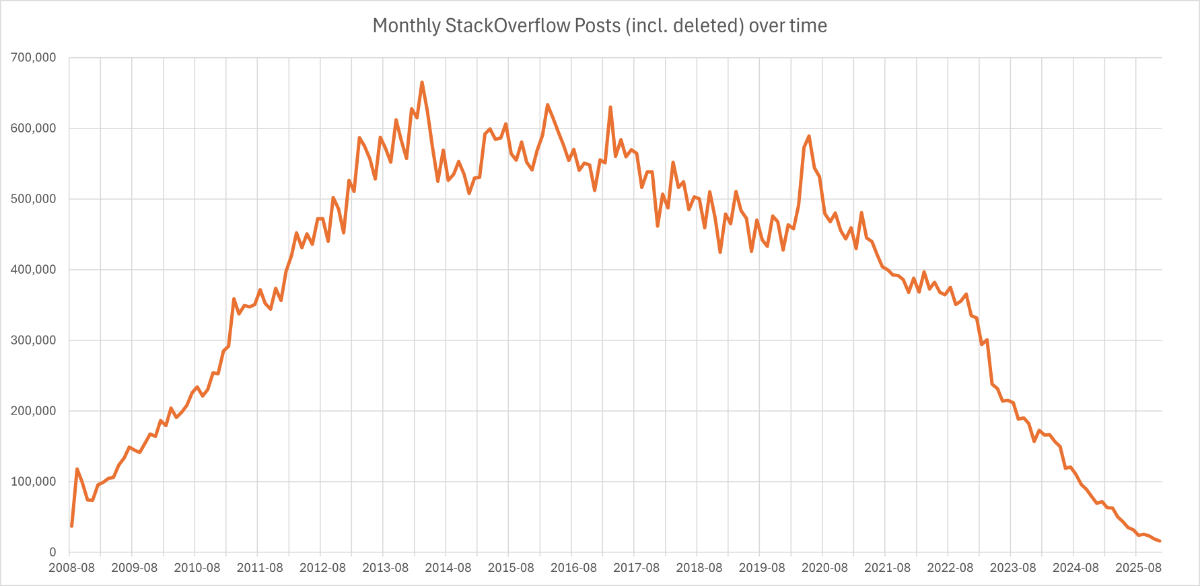
I also think that its AI, especially for new users. I mean AI is good at coding or spotting errors and asking an AI often gets you an answer way faster than starting a forum post. For example here is a chart of stack overflows posts
1 point
-
Using commands to acomplish the conversion, especially batch ones, will be very slow while displaying the DXF graphics. Why not use ODBX? 1) Create a dbx doc 2) DXFIn the dxf file 3) Saveas the dbx as dwg _$ (vlax-dump-object dbx t) ; IAxDbDocument: nil ; Property values: ; Application (RO) = Exception occurred ; Blocks (RO) = #<VLA-OBJECT IAcadBlocks 000002520fe578b8> ; Database (RO) = #<VLA-OBJECT IAcadDatabase 0000025243645708> ; Dictionaries (RO) = #<VLA-OBJECT IAcadDictionaries 000002520fe56598> ; DimStyles (RO) = #<VLA-OBJECT IAcadDimStyles 000002520fe57678> ; ElevationModelSpace = 0.0 ; ElevationPaperSpace = 0.0 ; Groups (RO) = #<VLA-OBJECT IAcadGroups 000002520fe55db8> ; Layers (RO) = #<VLA-OBJECT IAcadLayers 000002520fe57558> ; Layouts (RO) = #<VLA-OBJECT IAcadLayouts 000002520fe561a8> ; Limits = (0.0 0.0 12.0 9.0) ; Linetypes (RO) = #<VLA-OBJECT IAcadLineTypes 000002520fe57798> ; Materials (RO) = #<VLA-OBJECT IAcadMaterials 000002520fe56ce8> ; ModelSpace (RO) = #<VLA-OBJECT IAcadModelSpace 0000025279adffc8> ; Name = "" ; PaperSpace (RO) = #<VLA-OBJECT IAcadPaperSpace 0000025279ae0068> ; PlotConfigurations (RO) = #<VLA-OBJECT IAcadPlotConfigurations 000002520fe567d8> ; Preferences (RO) = #<VLA-OBJECT IAcadDatabasePreferences 00000252436bc1a8> ; RegisteredApplications (RO) = #<VLA-OBJECT IAcadRegisteredApplications 000002520fe57948> ; SectionManager (RO) = Exception occurred ; SummaryInfo (RO) = #<VLA-OBJECT IAcadSummaryInfo 0000025243646068> ; TextStyles (RO) = #<VLA-OBJECT IAcadTextStyles 000002520fe579d8> ; UserCoordinateSystems (RO) = #<VLA-OBJECT IAcadUCSs 000002520fe56bc8> ; Viewports (RO) = #<VLA-OBJECT IAcadViewports 000002520fe56868> ; Views (RO) = #<VLA-OBJECT IAcadViews 000002520fe56e08> ; Methods supported: ; CopyObjects (3) ; DxfIn (2) ; DxfOut (3) ; HandleToObject (1) ; ObjectIdToObject (1) ; Open (2) ; Save () ; SaveAs (2) T1 point
-
Something like this, may need to do more than once check directory exists and then check if DWG exists. ; check that pdf directory exists (setq dwgpre (strcat (getvar "dwgprefix") "\pdf")) (if (= (vl-file-directory-p dwgpre) nil) (vl-mkdir dwgpre) ) If does not exist returns nil (findfile "M:\\Mxxxxx\\Settings\\2024-2025\\B Setting\\B Setting 2024-2025.dwg")1 point