Leaderboard


Popular Content
Showing content with the highest reputation on 12/08/2025 in all areas
-
Just a follow up. I posted that long before I knew the importance of making sure that the Author of the code is noted as well as where I found the code. All credit goes to Gilles Chanteau. I have no idea where I found that code... It is probably somewhere here on cadtutor. I have since, started making sure that ifo is included as a header in the file, that way it doesn't look like I am trying to take claim for it and also, if/when something stops working I know where to go to address the issue. ~Greg original posting of code: https://www.theswamp.org/index.php?topic=29339.msg350137#msg3501372 points
-
Good day everyone! I've discovered new (old?) the possibilities of a true rectangle. It is very convenient to work with him! The only drawback is that the rectangle is unstable. You can create it and work with it only in the current file. If you then close and open this file, the properties of the true rectangle are lost. Is it possible to make it stable so that its properties are preserved? https://autocadtips1.com/2011/11/20/autolisp-make-a-real-rectacgle/ AutoLISP: Make a Real Rectangle Posted on November 20, 2011 by AutoCAD Tips A long time ago, AutoCAD used to make Rectangles and polygons as their own entities. When you made a rectangle and then did a LIST <enter> on it, it would show as a rectangle. Nowadays, these objects are those objects in their geometry but are made of polyline entities. So modifying these objects is sometimes hard. that’s where this routine steps in to help. This routine lets you create a rectangle and even after you continue working elsewhere in your drawing, you can come back to that rectangle and modify that object and it acts like how rectangles used to act in AutoCAD. Here’s how: TREC <enter> to start “True RECtangle” Create a rectangle how you normally create one When needed, this routine will let you drag a single corner and the rest of the rectangle’s geometry will adjust accordingly to keep its geometry as a rectangle. TrueRect.lsp
 1 point
 -
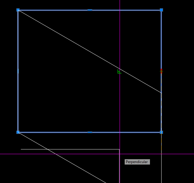
@Nikon Like I said - "For What It's Worth". Note also you can shorten the steps slightly by using the PERP object snap.
1 point
-
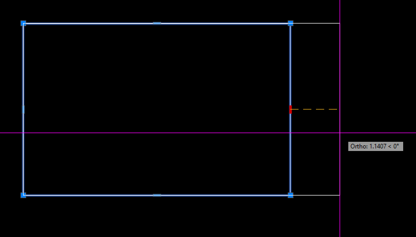
@Nikon FWIW - you can use the midpoint grips to drag the rectangle in straight directions to keep it square.
1 point
-
It can be done, but it requires creating a custom object using ObjectARX (C++).1 point
-
Ugh I think I watched your video too fast. I haven't had much time to do anything slowly lately I believe object reactors only survive the current drawing session. You must consider that the reactor was created relative to an object name, and object names change between drawing sessions.1 point
-
Inside the "initget" you use "Screening_50.ctb Fill_Patterns.ctb" with "_", and inside the "getkword" you use "Screening 50%.ctb/Fill Patterns.ctb", which is not equal as it in "initget". Everything must be equal. So, according from your's "initget", the "_" can't be in use, because it's in use for localization (for eg. "_RECTANG", "_LINE", etc.). From this link you can find this: Keyword Specifications The string argument is interpreted according to the following rules: 1. Each keyword is separated from the following keyword by one or more spaces. For example, "Width Height Depth" defines three keywords. 2. Each keyword can contain only letters, numbers, and hyphens (-). One of the possible solutions is to use this: (initget 1 "Monochrome.ctb acad.ctb Grayscale.ctb Screening50.ctb FillPatterns.ctb") (setq plotstyle (getkword "\nChoose plot style [Monochrome.ctb/acad.ctb/Grayscale.ctb/Screening50.ctb/FillPatterns.ctb] <Monochrome.ctb>:")) (cond ((equal plotstyle "Screening50.ctb") (setq plotstyle "Screening_50.ctb") ) ((equal plotstyle "FillPatterns.ctb") (setq plotstyle "Fill_Patterns.ctb") ) ) Best regards.1 point
-
@Clint Please give it a try (defun c:lay-nam-to-capital (/ (ACAD-OBJ ADOC LAY-COLL)) (VL-LOAD-COM) (SETQ ACAD-OBJ (VLAX-GET-ACAD-OBJECT)) (SETQ ADOC (VLA-GET-ACTIVEDOCUMENT ACAD-OBJ)) (SETQ LAY-COLL (VLA-GET-LAYERS ADOC)) (vlax-for lay lay-coll (vla-put-name lay (strcase (vla-get-name lay))) ) ;_ end of vlax-for ) ;_ end of defun1 point
-
Python, makes Batch processing a bit easier sometimes import traceback from pyrx import Ap, Db def capcaseLayers(db: Db.Database): lt = Db.LayerTable(db.layerTableId()) for name, id in lt.toDict().items(): l = Db.LayerTableRecord(id, Db.OpenMode.kForWrite) l.setName(name.upper()) def processDb(fpath: str): sdb = Db.Database(False, True) sdb.readDwgFile(fpath) sdb.closeInput(True) capcaseLayers(sdb) sdb.saveAs(fpath) #add new command @Ap.Command() def caplayers(): try: for fpath in Ap.Application.listFilesInPath("E:\\temp", ".dwg"): processDb(fpath) except Exception as err: traceback.print_exception(err)1 point
-
The PIP is here ‘pip install cad-pyrx’ https://pypi.org/project/cad-pyrx/, the project is here https://github.com/CEXT-Dan/PyRx It’s an amalgamation of BRX and ActiveX APIs. There’s some stuff for BIM as well.1 point
-
Obviously we don't have your batch LISP - I guess your company paid for this and so you are not going to be popular sharing that for all online. LISPs can be added to scripts - both as a command and as code. There are others out there such as ScriptPro and Lee Macs Script Writer which will do this. BigAl will often post snippets of scripts here to batch process files - last one he did was in the last week or so ago. You could even set this up as a stand alone script to do just the one task (see BigAls last example....) The first step for all is to get a LISP working as you want and well on a single file and then to do it as a batch (first time running the batch with a new LISP, perhaps check carefully that it doesn't do anything unexpected on other files). Plenty of examples out there to change layer names from one to another - have a look to see if you see one you like to use, or if there isn't am sure we can put one together - and use what is above as a started if you want to have a go, I think all the code you need is in the examples, just need to think how to change them to your needs1 point
-
Like @rlx this is a hard coded plot pdf using preset values, our dwg's used layouts one title block. the code is hard coded for a A1 sheet plotted as a A3 size. We just walked through the layouts and plotted. So does not matter what current plot settings are as they are ignored. We had multiple devices PDF, A1, A3 Color, A3 B-W. So code for each. (setvar "textfill" 1) (setvar "fillmode" 1) (COMMAND "-PLOT" "Y" "" "Plot To PDF" "Iso full bleed A3 (420.00 x 297.00 MM)" "m" "LANDSCAPE" "N" "W" "-6,-6" "807,560" "1=2" "C" "y" "Acad.ctb" "Y" "n" "n" "n" pdfName "N" "y" )1 point
-
maybe just something simple as : (setvar "filedia" 0) (command ".-plot" "No" "" "" "" (strcat (getvar 'dwgprefix) (getvar 'ctab) ".pdf") "No" "Yes") (setvar "filedia" 1)1 point