Leaderboard


Popular Content
Showing content with the highest reputation on 12/14/2025 in all areas
-
Hi Steven P and all the fine colleagues here, I have been distracted by producing content for a department-wide customization package based in BricsCAD. Steven P, Your comments are sound and will be pursued. My lack of focus on my programming learning shows - embarrassingly. Let's see what i can do about gaining LISP knowledge and its practical application! Thanks for everything. Clint1 point
-
Excellent and encourages me all the more to learn more than lean so much.. Found a solution as when using a text with a space in front, it's automatically ignored.. Just slip this in after the: v (vla-get-TextString o) v (vl-string-left-trim " " v) ;; https://www.cadtutor.net/forum/topic/26510-remove-the-space-from-a-text/page/4/#findComment-3245781 point
-
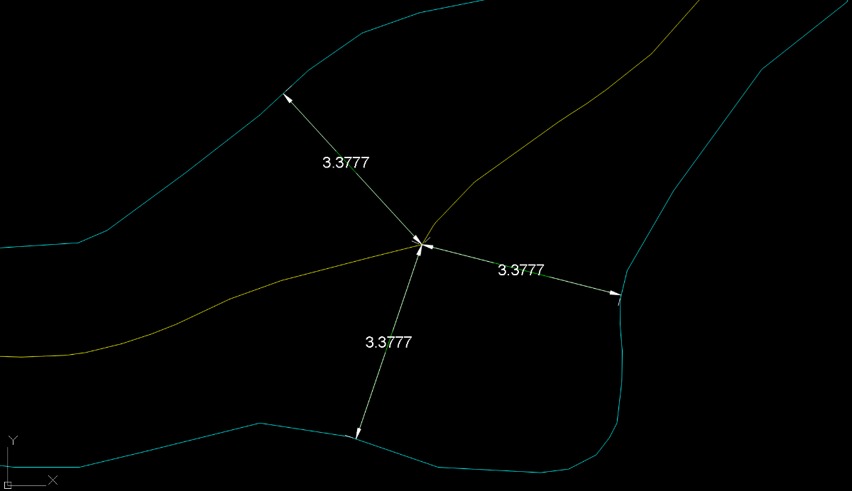
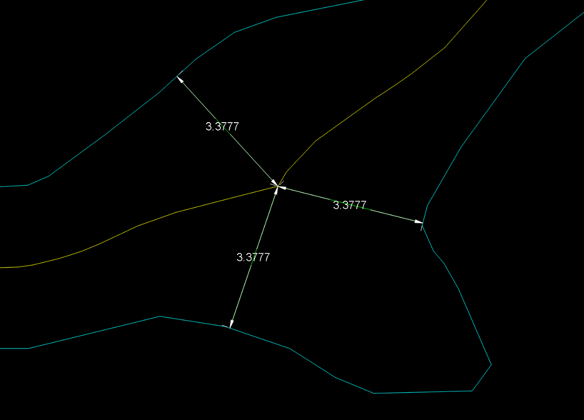
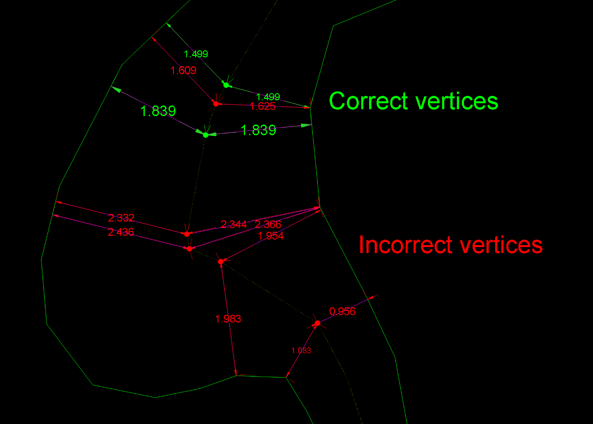
Obviously, this has now become something more than just the search for a solution to a single user’s problem. First of all, I should say that I myself was also reluctant to accept the concept of equidistance advocated by @GP_ and @dexus For the simple reason that applying this principle forced me to accept that the centerline should be the same in these two drawings. Equidistance requires ignoring those areas of the margins that do not geometrically affect the axis. This, which initially caused me some resistance, I eventually came to accept conceptually when I realized that it could serve as a criterion for defining what is a “recodo/inlet” and what is not. So I have abandoned my previous approach and adapted it to this new situation. Having made this clarification, I must say that this concept of equidistance makes the calculation of a centerline more feasible. I’ve been running some tests with Dexus’s latest code, which is the best so far. However, I’ve discovered some “holes” that I hadn’t noticed before. I’m attaching a few images showing this. In my view, these are conceptual errors rather than geometric limitations. And what can we consider “geometric limitations”? I believe that, in any case, every vertex of the centerline must be equidistant from both margins. If this is not the case, the result is not correct. However, the intermediate regions along each segment may be subject to geometric limitations depending on the desired precision. Therefore, in bends or turns, the points taken within the adjustment or “problematic” segments may deviate (within a tolerance) from strict equidistance. The goal, therefore (in my opinion), should be to achieve equidistance at every vertex and to remain within a tolerance in the intermediate zone of each segment. After everything written here so far, some might wonder: is it really possible to obtain a centerline that meets these requirements? As far as I’m concerned, I’m running some tests. GusanoAcad.mp4 I’ll post something over the weekend
 1 point
 -
Yes, but as it for as Title name for the topic. The plot is different. So, you're code will certenatly accomplish the desired result.1 point
-
As @Clint ask for1 point
-
Yes, this will substitued all layers into the UPPERCASE.1 point
-
If I getted correct, this can be accomplish, but you need to do a systematization in naming the layers. One of the approaches can be to make an .txt file in which you will store the systematizated layers (the proper order must be, for e.g. "Tropic,Train,Traffic" or "Tropic\n" "Train\n" "Traffic\n" etc. The \n means new line). Then, you will run the code from my post, get an list of layers inside the drawing, then select desired layers to matches with .txt file from which you want to get a proper names (for e.g. in .txt file you have the layer name "TrAffiC", after choosing the layer "Traffic" in the drawing with "TrAffiC", you can substitued with proper name).1 point
-
@Clint Please give it a try (defun c:lay-nam-to-capital (/ (ACAD-OBJ ADOC LAY-COLL)) (VL-LOAD-COM) (SETQ ACAD-OBJ (VLAX-GET-ACAD-OBJECT)) (SETQ ADOC (VLA-GET-ACTIVEDOCUMENT ACAD-OBJ)) (SETQ LAY-COLL (VLA-GET-LAYERS ADOC)) (vlax-for lay lay-coll (vla-put-name lay (strcase (vla-get-name lay))) ) ;_ end of vlax-for ) ;_ end of defun1 point
-
Obviously we don't have your batch LISP - I guess your company paid for this and so you are not going to be popular sharing that for all online. LISPs can be added to scripts - both as a command and as code. There are others out there such as ScriptPro and Lee Macs Script Writer which will do this. BigAl will often post snippets of scripts here to batch process files - last one he did was in the last week or so ago. You could even set this up as a stand alone script to do just the one task (see BigAls last example....) The first step for all is to get a LISP working as you want and well on a single file and then to do it as a batch (first time running the batch with a new LISP, perhaps check carefully that it doesn't do anything unexpected on other files). Plenty of examples out there to change layer names from one to another - have a look to see if you see one you like to use, or if there isn't am sure we can put one together - and use what is above as a started if you want to have a go, I think all the code you need is in the examples, just need to think how to change them to your needs1 point
-
Could go with a third Middle option. (setq layname (ApplyCASE "LAYERNAME")) LaYeRnAmE .... (defun ApplyCaSe (s / i n ch out) (setq n (strlen s) i 1 out "") (while (<= i n) (setq ch (substr s i 1)) (setq out (strcat out (if (= (rem i 2) 0) (strcase ch T) (strcase ch) ) ) ) (setq i (1+ i)) ) out ) -Edit or a more realistic Option Only first letter UpperCase (setq layname (ApplyCASE "LAYERNAME")) Layername (defun ApplyCase (s / i n ch out) (setq n (strlen s) i 2 out (strcase (substr s 1 1) T)) (while (<= i n) (setq ch (substr s i 1)) (setq out (strcat out (strcase ch)))) (setq i (1+ i)) ) out )1 point