Search the Community
Showing results for tags 'block insert'.
Found 7 results
-

Insert Block in-between two Points using Autolisp
subodh_gis posted a topic in AutoLISP, Visual LISP & DCL
Many a times it requires to show the same block with different angle and scale. Rotating each block to a required angle, and scaling it as required will take a lot of time so can we Insert Block in-between two Points in the angle and scale of points selection using Autolisp . I am using AutoCAD 2004. Thank You ! -

Block Library only partially loading! Help!
Pander93 posted a topic in AutoCAD Bugs, Error Messages & Quirks
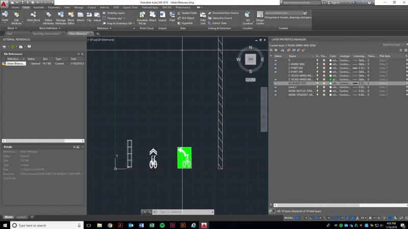
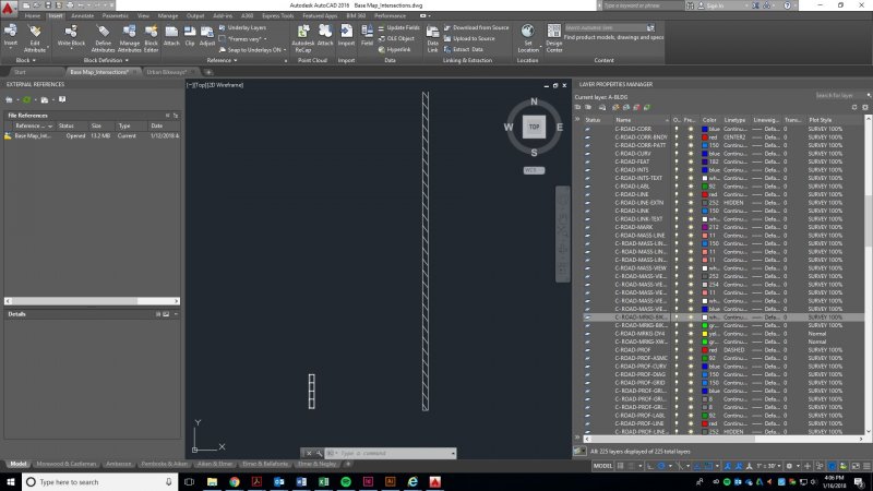
I made a Block Library with 4 objects in it, which I proceeded to insert into a drawing. However, only 2/4 of the objects inserted. The layers are not frozen, locked, or invisible. I've attached two screenshots. Please help me! I've been messing with this for hours.
-

Autocad Block Replacment
jaycopes posted a topic in AutoCAD 2D Drafting, Object Properties & Interface
Hi All, I hope i have put this in the right section of the forum. Introduction to my Queries: I am working on a 2D housing layout, which has multiple houses, roads, paths and trees, ect. For the record I use Blocks for the houses and within each block contains details such as House Name, Engineering Details (Rain water Pipe, Soil Vent pipe), Hatch Colour, roof line and entrance indication. The problem: Quite often I will have to mirror and rotate the houses to give variation for the elevations and general design of the layout. Now the problem I have, is when using the mirror cmd. The mirror cmd also mirrors the text which mean I have the choice of 2 things: A- explode the house block and flip the text back. B- make an additional mirrored blocks for each orientation. the problem with solution B is i have to then insert a new block each time, which makes the Job very long winded and lengthy especially if i have say 1000 houses on the scheme. is there a way to have a block which allows you to replace it on the whim? Like a right click change to opposite block. or is there a way to make the text to always keep it orientation? despite being mirrored Thanks in advance Jason -
Does anyone know how to update a block already present in a drawing with a block pasted from another drawing. I cannot use insert block with a file named the same as the block in the current drawing because the pasted block (of the same name) contains a visibility parameter that if I explode before inserting loses the parameters. If I insert the same named block within a same named file to the current drawing the drawing holds onto the original block because it is within a block. Am I making sense.... I am hoping there is a work-around this to update the block.
-

Insert Blocks at Insertion Points of Selected Characters
nick777 posted a topic in AutoLISP, Visual LISP & DCL
Right now I have 15,000 drawings that use letters instead of symbols, an artifact of a now defunct CAD software that translated the letters into symbols. I'd like to remake this in AutoCAD by inserting blocks at the location of those letters. I cannot find instructions on how to do this anywhere, and I need to add the following things to my code: 1 - Insert a set of blocks from another drawing. 2 - Select a specific letter from text in a specific layer in code 3 - Insert one of the newly inserted blocks at the insertion point of the letter 4 - Delete the character as it is no longer needed (unless it was replaced, then it wouldn't be there anymore) Example: Import set of blocks from template drawing. Select from layer "Curb Valve" the character "R" from a piece of text in the layer (exact match preferred if possible). Replace this symbol with a block named "CurbValve." I know you can get the X,Y of the text letter and manually type that in when you manually insert a block, so if you can detect this somehow and assign it to a variable, then use that variable to use as the insertion point of the block it would work. I just haven't been able to figure out how to do it programmatically. Thank You! -

Block Insert, Center and Auto Fill Attribute values, by clicking two points input
jfklimek posted a topic in AutoLISP, Visual LISP & DCL
I'm having trouble finishing this LISP. Can anyone help me out. The command line is telling me the command I'm entering 'roomtag' is unknown. It's probably something little but I can't seem to figure it out. Please help out if you can. Thanks! ;;;Place Room Tag in Middle of Room and Auto Fill 'x' and 'y' Attribute Values (defun c:RoomTag (/ pt1 pt3 rx ry pt5) (initget 1) (setq pt1 (getpoint "\nFirst Corner: ")) (initget 1) (setq pt3 (getcorner "\nOpposite Corner: ")) (setq rx (abs (- (car pt3)(car pt1)))) (setq ry (abs (- (cadr pt3)(cadr pt1)))) (setq pt5 ((+ rx pt1) (- ry pt3))) (command "_INSERT" "Tag_Room-Dim" pt5 "" "" pause pause rx ry "") (princ) -

insert block at distance & angle from first block, then repeat until stopped
BudPerry posted a topic in AutoLISP, Visual LISP & DCL
In this portion of a continuing program I'm putting together, a 4' block is inserted at a user point at a defined angle, then it is again inserted but this time 4' away at the same angle so that the two blocks form an 8' line. This is continued until the user stops the program. However, when the second block is inserted, it is rotated correctly but inserted somewhere north of where it is supposed to be. Obviously my polar calc or something is off: (defun c:blockinsert () ; ; ; ;part 5 of overall program ; ; (setq p1 (getpoint "\nSELECT POINT: "));user inputs first point (setq p2 (getpoint "\nSELECT NEXT POINT: "));user inputs second point - for use in part 6 of program ; (setq ang1 (angle p1 p2));get angle from user points (setq angreal (* 180.0 (/ ang1 pi)));convert from radians to degrees ; (setq blockpt "@48<");create a string that puts the next block at 48 inches away at same angle - from first point ; (command "_insert" "I:/documents/pog-panel-4" P1 "1" "1" angreal "1" "category text" "lf");first insertion at first point with two attributes filled ; (setq nextpoint (polar p1 angreal 48));add 4' from p1 at same angle (setq nextp (strcat blockpt angreal));this line is wrong, but I can't figure out how to get the info into the command line... ; (command "_insert" "I:/documents/pog-panel-4" nextp "1" "1" angreal "1" "category text" texttwo) ;insert 4' from last one ; ; ;now I need to add a line that will increase the amount from 4' to 8', ;then to 12', and so on in multiples of 4' - the block is 4' long ;until the user hits escape to stop the block insertions ;maybe use the repeat function? ; );end defun Any ideas on how to correct the insertion and how to create the repeat function and user break?