Search the Community
Showing results for tags 'flanges'.
Found 2 results
-

flanges b16.5 Dynamic Block Flange B16.5
jamildear4u posted a topic in Blocks, Images, Models & Materials
Dynamic Block of ASME B16.5 Flanges Rating 150# 300# 400# 600# 900# 1500# 2500# Sizes From 1/2" to 24" Watch The video of Dynamic Block Block https://www.youtube.com/watch?v=sdFtOPWggFo ASME B16.5 Flange Plan.dwg -

Newbie Inventor questions about folds and bends mostly.
Elforbo1987 posted a topic in Autodesk Inventor
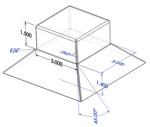
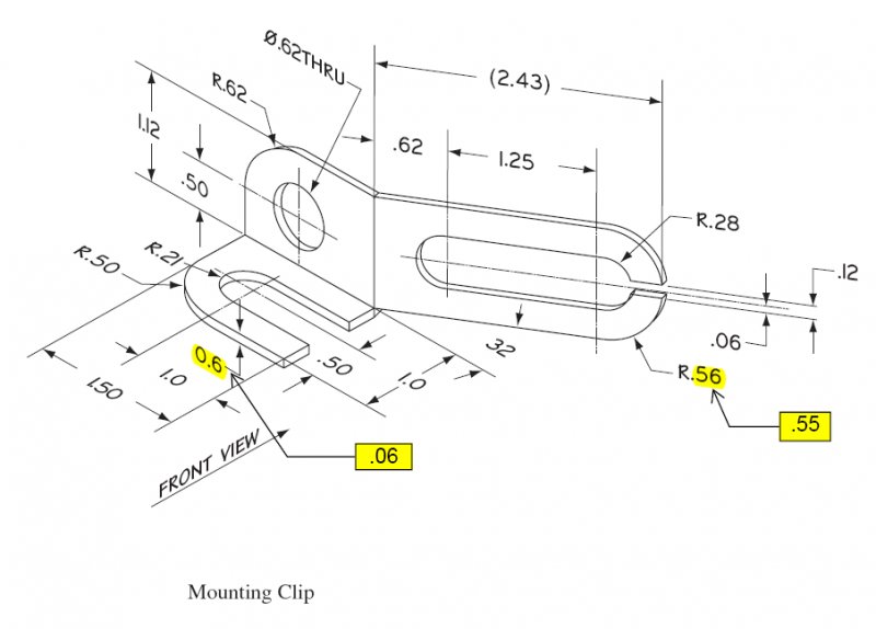
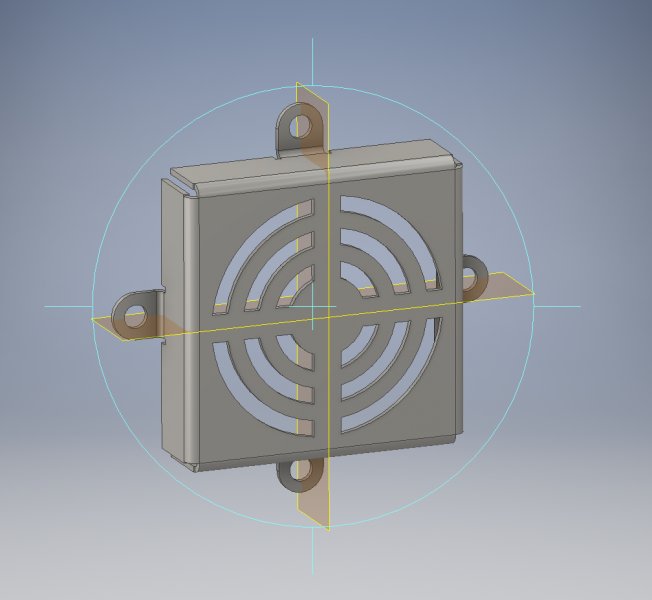
So i am in an inventor class and my teacher assigned the three drawings i attached below. 1.) How would i go about drawing this? There is no assigned thickness. I'm not sure what the height of the bottom pyramid shape is. I tried 1.4 at 45 degrees and that didn't work. 2.) My main problem here is that the folds or bends do not look the same. In the picture the fold or bend line is a single strait line for the long vertical piece going back 32 degrees, not a wide bend shape with 2 lines which is what i get. And the flat horizontal piece on the left has a straight 90 degree bend on the inside with what appears to be a rounded edge on the other side. Can you bend something to have that flat 90 degree corner in Inventor? Or would you have to cut to get that? 3.) Finally the fan cover. I did this drawing and everything came out great except the little flanges for screws are not flush with the back of the fan cover. It should all be flush on one level but mine stick out some raising it. How can you make the screw pieces flush? Thanks for your help. Sorry it's a lot all in one post.