Search the Community
Showing results for tags 'projection'.
Found 5 results
-
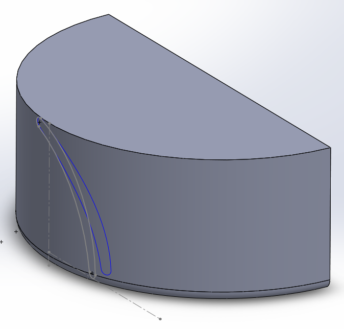
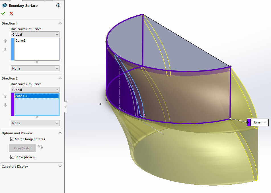
I want to create a surface from a projected curve (the blue line). I tried using the Boundary Surface tool, but I'm getting a mess of a surface.

-

"Unfolding" a circular surface to a planar surface ?
markusiuell posted a topic in Autodesk Inventor
Hi, I have a problem I can't seem to solve I have two pipes, installed eccentrically. The pipes will be perforated (made holes in) perpendicularly to the inner pipe axis. The perforations have a known phasing and density that will be true for the inner pipe. But due to the eccentricity of the pipes, the holes in the outer pipe will be random. What I want do do is to use Inventor to "unfold" the outer/larger pipe surface OD, to trace the holes down to a flat plane or surface. Then the plan is to print out this flat surface on a paper, wrap it aroud the pipe and drill the holes manually. Please find attached pdf that will help you understand my frustration. Can you help me with this? Please ask if you have any questions. casings.pdf -
Hello all, I have received a redesign from a sub that is a bit problematic. I will explain it as best I can. The plan has a main road alignment. I have received a redesigned pipe design. I have the pipe alignment, no problem there. It runs along the road alignment, not parallel, and crosses from one side of the road alignment to the other in several places. The issue is with the pipe profile. The sub created, reused, my road alignment profile and drew their pipe profile on it. They labeled station and elevations on their profile. The stationing is based on the road alignment and elevations are for their pipe profile. Since their profile is drawn on the road profile it is 'stretched' in some areas and greatly foreshortened in others. Does someone know of a slick way for me to project the pipe profile elevations to the pipe alignment so I can generate a feature line? Civil only wants to place the points on the road alignment. I'd just do it manually but it's about 3,500' and a lot of points. Thanks in advance for any help or ideas. Phil Additional info There are only a very few pipe profile elevations that match the pipe alignment geometry points.
-
Hey all, I'm trying to work on a code where I can project the Top and Side views from a cross-section of a W-Beam (see attached block for an example). I've tried my best but this is as far as I got before spinning my wheels. (Defun c:fd (/ d1 d2 d3 d4 p1) (SETQ D1 (GETDIST "\nWhat is Flange width: ")) (setq d2 (getdist "\nWhat is Flange thickness: ")) (setq d3 (getdist "\nWhat is Web thickness: ")) (setq d4 (getdist "\nWhat is Depth: ")) (setq p1 (getpoint "\nBasepoint for top view: ")) (command "line" p1 @d1.0 ) ) Please note that this lisp is only for W-Beams, I do not need a catch all lisp. If required I should be able to modify this lisp to suit future needs. Lastly, I haven't added any error catching as I'm not at that stage yet. Any help is greatly appreciated. W10x45 (W250x67).dwg
-

2D Representation - Flatshot - 2D & 3D Geometry??
CaveMan posted a topic in AutoCAD Drawing Management & Output
Good Day Have a drawing with multiple xref's , Blocks within it. Drawing geometry is a combination of 2D and 3D. Would like to project this onto a 2D plane - "FlatShot?" and then save it as another drawing. Main reason for this is for a KeyPlan - routing diagram for a plant If anyone knows of a quck method would greatly appreciate Software been used AutoCAD 2010 & 11 Regards CaveMan