Search the Community
Showing results for tags 'profile'.
-
I'm using 2004 and drawing a profile for a utility. I need a 25' radius for my vertical curve for this utility line. I'm wondering how people draw this radius if there is a vertical exaggeration in the profile. Horizontal scale is 1"=20' and Vertical scale is 1"=5'. Thanks!
-
Hello to everyone. I have a file that can draw the longitudinal path of a water line, but it lacks some technical details, such as drawing the boundaries of the table beneath the chart and signing the depth calculated by the lisp as it is, rather than minus a distance estimated by the pipe's radius. Please seek assistance from people with relevant experience. Attachment: Assign Excel and Lisp next to a CAD file that almost has a work model with some notes. WATER PROFILE SPREADSHEET.xlsx TEST PROFILE NOT COMPLETING DRAWING BY LISP AND XLS.dwg WaterProfile.LSP
-
Goodday Everyone, I have created a vba code for creating Longitudinal section (inputs from excel), also I want to make a gap between the profiles if a row was empty in excel. Can anyone guide me through this!? Thanks Regards, Vasanth. S
-
We are designing a regulator station and currently use inventor for majority of our projects as they typically require high detail. For this smaller project we decided it would be more beneficial to do it all in C3D. We don't require any 3D views or layouts but do need the profiles showing fittings/piping. Is there a database where a lot of this is stored (3R Elbows, Thredolets, Caps, Blow-downs, Valves, etc.)? I know that manufacturers sometimes has a lot of their information on their website and even in .dwg format but it seems like we will need to redraw a lot of what we need based on the specifications/dimensions. Any information is useful, thank you.
-
Hi, Good day to you all.I'm new to this forum. I hope you people can help me out. I'm working on, automatic creation of title block with required scale setting in 'Model space' not in layout. by clicking a button or comment, it should ask the user to select the 'title blocks' among the list, which is in 1:1 scale. Then it should ask the user to select the scale among '1:2, 1:10, 1:20'. once selected it should scale the title block(eg. if 1:10 selected entire title block to be scaled to 10). also the size of dimension arrow and text size to be changed accordingly. Also we have a set of 10 drawing each as a blocks in it which we will be using as symbols on drawings. that should also get scaled accordingly whenever they gets inserted. please help.
-
Hello all, I am laying out a soldier pile wall and am having an issue with creating a top of wall profile. The piles are equally spaced and vary in height based on eg conditions. Does anyone know a way to have a vertical segment in a profile? My goal is to have my wall corridor have vertical steps when viewing and creating views and avoid having those little 'sloped sections'. Any help or suggestions are appreciated. thanks, phil
-
Hi all:D, I have a huge request linked to an lisp received from a friend. Lisp do next operation ... select a file type PRN (Ex 1.PRN), required datum level (ex:90) value and automatically draws longitudinal profile with data from file PRN (formatted text space delimited) . my request is ... can someone help me to do lisp advanced form of longitudinal profile as shown in attached “LGTR.dwg” file(in green rectangle). When I upload file 2.prn in lisp drawing the result from the green box. I would appreciate if someone can suggest an idea or if modify the Lisp as showing the longitudinal profile in green border. to use prn file please del .txt lisp command is LGTR datum level for my files is 90 Thank you for your time. LGTR.dwg LGTR.LSP 1.prn.txt 2.prn.txt
-
 HI THERE! AUTOLISP FOR Copy of data from excel to acad.xlsxIN TEXT 90DEG ROTATED, NEED A AUTOLISP THAT CAN FUNCTION TO CREATE PARTIAL DISTANCES(0.000.000), CUMULATIVE DISTANCE(0+000.000) BASED ON THE LENGTH BETWEEN THE EACH VERTEX OF THE POLYLINE (APPROX. 3.69KM), PLEASE FIND THE ATTACHED DRAWING, THANKS IN ADVANCE PLEASE HELP, CREATE A LISP FOR PL.dwg
 -
Hello.. I have this cross section lisp routine and i was hoping someone could help me change it a bit... What it actualy does is ask first where to plot the profile, start and end point of the section and then either you select a block with an attribute called ELEV or you have to pick a point and insert the elevation manualy.... What i would like it to be was... click point, either it's a block with attribute elev or pick a point and insert manualy elevation, and when i have all the points needed, ask where i want it drawn and voilá. Thanks in advance. QPROF.lsp
-
Hello, I want to be able to add a profile view label that will label the station and profile elevation by entering the station and having the label 'extract' the elevation from a selected profile. The inquiry tool will report the elevation but that's not what I require. I have also been unsuccessful in creating an expression that will do this. To sum it up, I want to add a profile view station and elevation label by selecting or entering the station and then selecting/picking the design profile. Any and all help is appreciated. thanks, phil
-
Hi, all. Is there a way of importing a profile *.arg file (in the "Options"|"Profiles" tab) and have it simply change settings under the "Options"|"Files" tab and nothing else? I wouldn't mind going into the *.arg file and deleting lines, as long as I knew which ones were important. But would the profile import just fine if it did not have all the lines? For example, if I deleted everything in there that did not pertain to search paths, would it still load up? Right now, when we load a profile *.arg file it changes everything... the cursor size, background color, buttons, the way it selects elements, etc., and it would be very important that each user could upload a profile, based on which client standards one's working on that day, and have their customizations untouched. It might simply be that it can't be done, or i just don't know enough about profiles, but any help on this issue would be much appreciated. Thanks, Edgar
-
Hello all, Does anyone have a good resource for the definitions of vertical curve types? Something with examples along with definitions, like a pdf hopefully. Any and all help and links are appreciated. Happy Thanksgiving, Phil
-
I got a new system and trying to transfer settings. With this new system I set it up with my main user account to "not" have admin privileges. This way if I ever do get a virus, it doesn't have privileges. If I run acad in admin mode it defaults to initial setup and I cannot find a profile file to import. Custom Settings Import is done outside of running acad. The path of AppData....Support/Tool Pallets is tied together in admin mode and pallets show up, but lost in non-admin mode. Any ideals or help would be greatly appreciated.
-
Hey everyone. I am new to AutoCad due to the fact that I am helping out my father-in-law with his Civil Engineering business. I need help with surface profile view. I have created the alignment and created the profile (in model view) but when it generated the numbers were all on top of each other and its a giant mess. How do I fix this with out trying to individually move each number and try and find a spot for it.
-

after loding lisp : "error no function definition , ACET-STR-FORMAT"
Salama posted a topic in AutoLISP, Visual LISP & DCL
Hi, currently i found on the web , this lisp to draw Road profile or any other profiles by the lisp that contains two commands : 1- " NGL " : To draw natural ground elevation in terms of station and elevation from an excel sheet with a Datum . 2- "PGL" : tO DRAW DESIGN ELEVATION from excel sheet too , with same datum. the lisp states an error message "error no function definition , (ACET-STR-FORMAT ) after loading " NGL" and entering datum , BUT it work with " PGL" without any error ... ??!! i use AutoCAD2012 ? , what do you think that the problem is ? lisp and excel are attached . https://www.mediafire.com/?dqbumocn3gm3132 https://www.mediafire.com/?dqbumocn3gm3132 PROFILE #NGL# - #PGL#.lsp
-
Hello all, I have received a redesign from a sub that is a bit problematic. I will explain it as best I can. The plan has a main road alignment. I have received a redesigned pipe design. I have the pipe alignment, no problem there. It runs along the road alignment, not parallel, and crosses from one side of the road alignment to the other in several places. The issue is with the pipe profile. The sub created, reused, my road alignment profile and drew their pipe profile on it. They labeled station and elevations on their profile. The stationing is based on the road alignment and elevations are for their pipe profile. Since their profile is drawn on the road profile it is 'stretched' in some areas and greatly foreshortened in others. Does someone know of a slick way for me to project the pipe profile elevations to the pipe alignment so I can generate a feature line? Civil only wants to place the points on the road alignment. I'd just do it manually but it's about 3,500' and a lot of points. Thanks in advance for any help or ideas. Phil Additional info There are only a very few pipe profile elevations that match the pipe alignment geometry points.
-
Hi, I've recently had a problem with my windows profile at work and they had to create a new one. When I first launched AutoCAD (2012) using the new profile it was with the default workspace. I found the old roaming folders and copied them across to my new windows profile, thankfully I got my old workspace back. However, I have since noticed that all my previous settings in the SYSVDLG and OPTIONS have also reset. Seems my old profile didn't carry across, I tried searching for an .arg file but found nothing whatsoever. This isn't a major pain as I've just changed the settings as I encounter one, but still, it would be good to be able to find my old settings. So a few questions, I think you know where I'm going with this: 1. Is it possible to retrieve my old SYSVDLG, OPTIONS and profile settings? 2. Is it a good or bad idea to move my .cuix file somewhere away from the windows user profile and point AutoCAD to it? Or is it better to keep it where it is by default and make a backup after I make changes to it? If possible, can the same be applied to the SYSVDLG, OPTIONS and user profile in case something like this happens again. Ideally I'd like to be able to either move these files permanently to location of my choice, else a backup will have to do. Also, any other info which will help will be greatly appreciated. Thanks in advance.
-
Ok, I know that I found instructions to do this once through a google search, but have since been unable to find it again. I have two streets which intersect and I need to leave the profiles blank from curb return to curb return at the intersections. I know that I could make two separate profiles for each street, but I've already set it up with just one profile each and I'm lazy and don't want to do it again. I know that there is a way (maybe through the profile properties?) where you can "mask" or "hide" one profile through a certain station range. We have all of our profiles stored in a base file, and then data shortcut them into our cut sheets. I know that I need to apply this "mask" in the base file, and then turn it on in the cut sheet because that is what I did last time. Any help would be very appreciated
-
Running Civil 3D 2010: It seems to me that after a long session in DeepCAD, one loses the ability to use the profile toolbar. Has anyone else experienced this? It can easily be fixed by closing out of the drawing (and sometimes even the application) and then starting back up... But that just seems like an archaic approach to a present-day problem. Honestly, I don't know much about the system variables, but it seems like something is resetting itself during my CAD sessions. I haven't tried it yet, but after brainstorming, I feel like there has to be some forgotten variable that resets and leaves you wondering what happened. I refuse to believe that shutting down and starting over is the be-all, end-all solution.
-
Hi, I have recently started using AutoCAD 2012 and after changing my OPTIONS settings I renamed the default profile (or whatever it is called) so it is the only profile in the list. Now every time I launch AutoCAD, all of my settings remain except for the font I use in the command line area despite the current profile being the one I renamed and the correct font shown as selected in the OPTIONS > Fonts. I have to manually select my profile to get it to display as intended. How can I fix this? On a side note, is it true to say that profiles store settings in the OPTIONS menu while workspaces store eveything visible on screen, like toolbars etc? Is there anything I can do to link everything to one setting or config file? I've also seen another more advanced options menu mentioned in this forum but I forget where. Can anyone tell me how to access this? I think users Dadgad or dbroada post it a few times... Sorry for asking so many questions and thanks in advance.
-
I have a project with alots of intersections and alot of stuff thats built around a main alignment that must be edited in the start/ beginning. So i have to move the geometry a bit and im worried about whats happening with my profile. I want the profile to stay the same after station 60. I used the station control and picked it as reference point and it works fine except for that my new geometry of the alignment doesnt start at 00.00, but at -07.50 ... Is there some way i can change so that the new start is labeled at station 00.00 without movin my profile?? I use civil 3d 2012.... Thanks!
-
I subscribe to some threads which I like and I thought they are accessible through my profile. I couldn't find them in my profile. Where are they?
-
Hello newbie here, So my project is to design a sewer from elevation points we surveyed out in the field. So far I have created a polyline which represents the surface we surveyed. Our instructor gave us a template with a profile grid on the bottom half. I have place this polyline inside the grid but I am having trouble scaling this to the correct vertical and horizontal scales. I have made the polyline into a block. I know I can adjust the X and Y scaling of the block under properties--> geometry but I am confused about how to set these values correctly. I need a vertical scale of 1"=2' and a horizontal scale of 1"=20', I am just confused about what I should enter into the X and Y scale factors to give me the correct scaling. Any help at all is appreciated. Thanks
-
Lets say I wanted to put a profile image generated from google earth (a Jpg or Bmp ) on a layer in a side view of autocad for reference, How would I insert it. I have done that with 2008 but can't do it in 2012.The image from google earth has dimensions on it so it would be easy to scale properly to my drawing. So I would like to be able to put it on my dwg. I don't know what (tags:) means on this page. Also I have saved the image on my computer and I have tried to show it on this post but don't know how. The image is a jpg The format of this posting is asking for a url. as you will see I tried to put C:\users\onkelbob\desktop\profile.jpg below but it didn't work. Dumb of me huh.
-

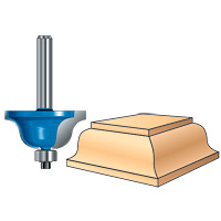
Drawing a router profile onto a piece of wood
JamFam posted a topic in AutoCAD 3D Modelling & Rendering
Greetings everyone. I am using AutoCAD 2010 3D and though I am reasonably comfortable with 2D, the 3D stuff is hurting this wee brain of mine. Here is my objective. I have drawn a 3D image of a piece of wood in the 3D model space. I want to profile the edges of the wood with a router design, in this case a Roman Ogee, (see drawing). I have drawn the Roman Ogee in 2D, copied and pasted it into 3D then extruded it. I moved the Roman Ogee router profile into the area at the edge of the board I want the profile to be but I just can't figure out how to get the router profile to run along all 4 edges of the board to look like the image above. Can anyone help with a step by step procedure? Thanks