Search the Community
Showing results for tags 'survey'.
Found 12 results
-

Block showing distance with arrow pointing in correct direction?
Akeane posted a topic in AutoLISP, Visual LISP & DCL
So the problem im having is i have code that runs to show the offset of measured points to design points, unfortunately the code works by inserting one of 4 predefined blocks for NSEW, or one of 4 when in 2 directions; only showing orthogonal distances. These work by passing through the distance to the block tag, and then comparing the EW, and/or NS values to determine the correct arrow direction to insert the correct block. What i want is instead of using orthogonal distances, is to have an arrow block within these blocks, that changes the direction of the arrow, based on a bearing that you pass through. eg if the horizontal distance between 2 points is 25mm at a bearing of 45 degrees, then a tag is created as per normal with 25 and an arrow point 45 degrees. Any good ideas? I've looked in the forums and couldn't find anything to solve this. Attached is an image of what i have currently made, note the aligned one showing 130mm is kinda what i want, but that arrow is not dynamic, it just goes left or right and the whole block is just rotated to show the bearing. It makes for a messy plan and a lot of neck craning to present to a client -

triangles by three sides - for irregular houses surveying
harinezumi posted a topic in AutoLISP, Visual LISP & DCL
This routine helps me to draw surveys of irregular spaces, with triangles (sides and diagonals). It asks for the measures of the three sides, insertion, lying and direction (clockwise/counterclockwise). Do you have any idea to make it better? I would love for example to be able to see the ghosted triangle (elastic band animations?) when I place and rotate it, and a quicker clock/counteclock switch. Thank you for any advice and improvement (sorry - many comments are in Italian only) ;;; ***************************************************************************************************** ;;; ARsurvey v0.1.0 © 2009 Andrea Ricci http://andrearicci.it <°))); ;;; ;;; IT ;;; tentativo 01 di creare una routine per semplificare l'immissioni di triangolazioni di rilievo ;;; il prodotto finale dovrebbe, date tre misure, verso, punto di inserimento e allineamento, ;;; tracciare un triangolo delle misure date nel punto e con l'allineamento dato ;;; ;;; si rilascia con licenza LGPL v3.0 <http://www.opensource.org/licenses/lgpl-3.0.html> ;;; per cui, fra l'altro, non è possibile ricavarne un prodotto commerciale, e qualsiasi ;;; derivato (modifiche, incorporamenti in altro codice) deve avere la medesima licenza ;;; ;;; EN ;;; draws a triangle given three sides, insertion point and alignement, ;;; intended to help in the boring survey procedure ;;; relased under the LGPL licence v3.0 <http://www.opensource.org/licenses/lgpl-3.0.html> ;;; ***************************************************************************************************** ;;; IT ;;; uso: ;;; avviare il programma digitando "srv" (da SuRVey). ;;; Il programma chiede anzitutto tre misure (si può inserirle con mouse), ;;; poi punto d'inserimento e direzione, infine chiede se il triangolo vada ;;; tracciato in senso antiorario (default, basta dare l'invio) ;;; oppure orario (premere C per "clockwise") ;;; ;;; EN ;;; use: ;;; start the command with "srv" (as in SuRVey) ;;; The routine will ask you for three sides' measures (you can input them by mouse), ;;; then the insertion point, and the direction. Lastly it will ask you if you want ;;; to draw it counterclockwise (default, just press "enter") or Clockwise (press "C") ;;per convertire radianti in gradi (defun rad2grad (radianti / gradi) (setq gradi (* radianti (/ 180 pi))) gradi ) ;; per convertire gradi in radianti (defun grad2rad (gradi / radianti) (setq radianti (* gradi (/ pi 180))) radianti ) ;; dati tre lati ricava angoli interni (formule di Briggs - http://www.math.it/formulario/goniometria.htm) (defun briggs (latoadiacente1 latoadiacente2 latoopposto / corner) (setq corner ; angolo opposto al lato sideC (abs (* (atan (sqrt (/ (* (- p latoadiacente1) (- p latoadiacente2) ) ;fine_numeratore (* p (- p latoopposto) ) ;fine_denominatore ) ;_end frazione ) ;_end radice quadrata ) ;_end reciproco tangente 2 ) ;_end moltiplica per 2 ) ;_end abs (rimuove eventuale "-") ) corner ) ;_end funzione briggs ;;; inizio main function (defun c:srv () ; mnemonico da SuRVey (signature);_he he he (princ "\nCommand SRV (SuRVey) v0.1.0 © 2009 Andrea Ricci http://andrearicci.it _m__(*_°)__ooo____" ) ;(setq lprecision (getvar "luprec")) ; memorizza la precisione lineare in uso per successivo ripristino ;(setvar "luprec" 8) ;(setq aprecision (getvar "auprec")) ; memorizza la precisione angolare in uso per successivo ripristino ;(setvar "auprec" 8) (initget 103) ; non consente valore nullo (+1), zero (+2), negativo (+4), usa linea tratteggiata (+32), ignora Z (+64). (setq sideA (getdist "\nfirst side lenght: ") ) (initget 103) (setq sideB (getdist "\nSecond side lenght: ") ) (initget 103) (setq sideC (getdist "\nThird side lenght: ") ) ;; controllo che sia un triangolo (la somma dei lati minori supera il lato maggiore?) ;; is the triangle possible? (if (or (> (max sideA sideB sideC) (- (+ sideA sideB sideC) (max sideA sideB sideC)) ) ;_">" valuta se un valore è maggiore dell'elemento alla sua destra (= (max sideA sideB sideC) (- (+ sideA sideB sideC) (max sideA sideB sideC)) ) ;_oppure uguale ) ;_end or (progn (alert "sorry, not a triangle") ;;(setvar "luprec" lprecision) ;_resetta la precisione lineare originale ;;(setvar "auprec" aprecision) ;_resetta la precisione angolare originale (gc) (princ) (exit) ) ;_end progn ) ;_endif (initget 65) ;non consente valore nullo (+1), zero (+2), negativo (+4), usa linea tratteggiata (+32), ignora Z (+64). (setq pointA ;origine triangolo (getpoint "\nInsertion Point: ") ) (initget 103) ;; angolo iniziale (setq delta (angle pointA (getpoint (princ pointA) "\nFirst side direction") ; (princ pointA) all'interno di getpoint serve a piazzare l'origine della linea tratteggiata ) ) (princ (strcat " [angle= " (rtos (rad2grad delta) 2 8)"]")) (setq p (/ (+ sideA sideB sideC) 2)) ; p= semiperimetro ;; angoli ottenuti con briggs' formula ;; (setq alpha (briggs sidec sideb sidea)) ;; (setq beta (briggs sidea sidec sideb)) (setq gamma (briggs sidea sideb sidec)) (setq gamma (- pi gamma)) ;_correzione dell'angolo reciproco **************************************** ;; correzione del verso di tracciamento (default: antiorario) http://www.lee-mac.com/promptwithdefault.html (initget "Cw or ccW") (setq dir (getkword "\nSpecify order of given measures [Cw/ccW (clockwise/counterclockwise)]: <ccW>" ) ) (if (= dir "Cw") (setq verso -1) (progn (setq dir "ccW") (setq verso 1) ;_else ) ;_end progn ) ;_end if (princ dir) (setq dir nil) ;_resetting the variable for next use ;; end of triangle direction routine ;; punto B in coordinate relative da pointA e radianti (setq pointB (strcat "@" (rtos sideA 2 8) "<" (rtos delta 2 8) "r" ) ) ;; punto C in coordinate relative da pointB e radianti (setq pointC (strcat "@" (rtos sideB 2 8) "<" (rtos (+ delta (* verso gamma)) 2 8);_corretion by direction->verso "r" ) ) ;; disegno della polilinea (setq snapmode (getvar "osmode")) (setvar "osmode" 0) (command "_.PLINE" pointA pointB pointC "_close") (setvar "osmode" snapmode) ;; ;(setvar "luprec" lprecision) ;_resetta la precisione lineare originale ;(setvar "auprec" aprecision) ;_resetta la precisione angolare originale ;; stampa le tre lunghezze (princ (strcat "\n1st side= " (rtos sideA 2 8) "; 2nd side= " (rtos sideB 2 8) "; 3rd side= " (rtos sideC 2 8) ) ) ;| per verifica stampo l'ultimo lato calcolato, corrisponde con il terzo inserito? verify: is the calculated last side equal to imput?|; (princ (strcat " [Last side: " (rtos (distance (getvar "LASTPOINT") pointa) 2 8) "]" ) ) ) ;_end_defun ;;; ;;; ------------ Command Line Load Sequence-------------------------------------------- (princ "\nARsurvey v0.1.0 \n© Andrea Ricci, \n July, 2009....loaded.") (princ "\nARsurvey v0.1.0 ) (princ "Type \"SRV\" (SuRVey) to draw a triangle given tree sides, insertion point and alignment") (print) ;;;;;; -
I am having a hard time converting a .las file to create a surface in C3D & I was wondering if anyone had familiarity with this. I brought the .las file into ArcGIS and created a Raster then extracted contours from the raster but this did not work out the way I hoped. I see that C3D is able to open .rcp & .rcs files. I was wondering if this would be the route I need to take and how do I convert into either of those formats? One work around I've used is using Autodesk Recap to convert the files but my issues then stem from the surface thinking the trees are ground points.
-

Possible to give a node a Z value from text?
Clifford169 posted a topic in AutoLISP, Visual LISP & DCL
Long timer user first time poster. I have an old survey that we don't have the raw data for anymore. There are levels associated (in text form) to the nodes we have created from LSS, however the nodes themselves are all 2D. Is there a way to tell those nodes to shift their Z value to the height in the text line? I'm used to using LISPs though I'm not much of a writer for them! Looking forward to your responses. -
I've incorporated and created many LISP functions for surveying purposes in AutoCAD. I've been wanting to share them, so here goes. A lot of the functions reference other functions. I've used the naming scheme: mfcb* for My Functions CBass (me) mfcbLM for My Functions Lee Mac (because he is awesome) Many of these functions have been the work of others and I have revised them to my needs. Use them as you see fit. Enjoy! AutoCAD Blocks Edit: Minor text fixes. Sorry about that. Edit2: Optimizations. Edit3: Optimizations and error fixing. Edit4: More optimizations and a few new functions. Edit5: Optimized SPL function. Edit6: Fixed c:CLOSEST (iNdx was causing infinite loop). Edit7: Fixed multiple selections with c:MASK command (forgot to nil the XData and it would error). Edit8: Formatted Benchmark.lsp for readability. Edit9: Revised XData functions to preserve other application XData. Created menus for the functions. Edit10: Added dropbox link to AutoCAD blocks. Benchmark.lsp PointCodeList.txt acaddoc.lsp Global Functions.LSP Menu.zip
-
I just have normal autocad 2016, nothing fancy like civil 3d. I was wondering, is there a way i can bring in a survey point data file (.txt or .asc) into Autocad. Maybe by something in program by default, or a 3rd party plug in that is compatible with autocad. I don't want to spend way more money for the Autocad civil 3d license.
-
Hi Everyone, I have to survey and draw up a set of plans for a building that has a number of walls out of square. What's the best way to do that these days. Anticipated answer 1: "I choose a wall to act as the Datum x and Y axis and then run my measurements off these." Anticipated answer 2: "I set up a couple of laser lines and work everything off these" Aniticipated answer 3: "there's some app that does it for you automatically - didnt you know"
-
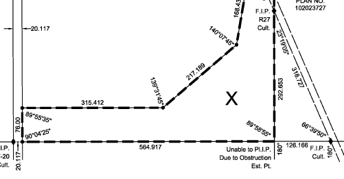
Hi Everyone, Just wondering if anyone knows of a good lsp routine for doing the following, or if anyone knows how to do this with built in capabilities in AutoCAD 2015. Basically I want to annotate angles and distance for survey drafting so I can produce plans that look like this plan that I've attached. I have a routine that will give me the distance and bearing and place it parallel to a line but now I need to be able to do the same with the angle (in degrees/minutes/seconds) and distance (in meters) so that the angle appears as it does in the attached sample. Any help would be most appreciated! Thanks!

-
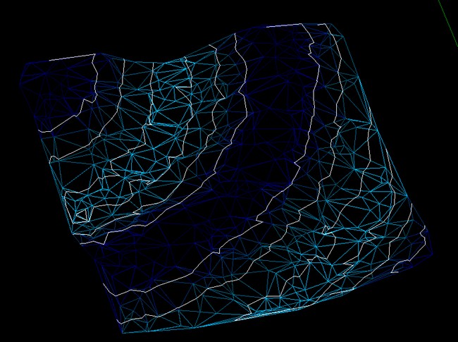
I found an interesting routine that allows coloring 3Dfaces a survey, according to altitude. By chance, someone knows a similar routine but which takes into account the contours/curves? (See image with the results of routine indicated)
-
I am looking for a way to import my regular p,n,e,z,d text files with a custom tag for the point number. For example when I collect OG shots I like to number them OG##(
-
 I have a drawing of a factory, with different equipment foundations laid out. I'm trying to do a type of surveying, get a distance and angle measurement from a specific set point in the drawing. So far i've only been able to use the Aligned Dimension function to show the distance between the set point and edge of a foundation (for example.) How can I show the angle as well on the same dimension line. Any help would be REALLY appreciated!