

Edges
Introduction
Edges exist where one surface meets another. Usually an edge is a surface edge detail such as pavers, a retaining wall or stepped features such as steps or terracing. These are usually formed by using the Loft Compound Object if the mapping for bricks or pavers need to follow the line of the edge as in real world construction. If the geometry is 'rectangular' then a simple Extrude modifier can be used with Box type mapping. Another method is to use the Sweep modifier
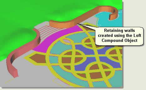
Here, the retaining walls and sundial surface edge are created using lofts and the steps (level/flat features) are created using extrusions
NOTE: Lofts are used for the walls here so that the brick material, applied later, will ‘follow’ the curve of the walls
Download Sample Data
kf303_files.zip (779kb)
Retaining Walls
- Either start from the previous stage or open kf303_01.max
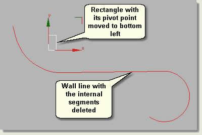
- Select Wall.01 and Wall.02. These are closed polygons created in AutoCAD to delineate the retaining walls in plan view
- Isolate Selection
- In segment sub object mode delete the inner (towards the meadow) and end segments to leave a wall line to serve as a loft path
- Draw a rectangle 0.5m wide and 1m high to serve as a loft shape
- Move the pivot point of the rectangle to the bottom left. This is the point at which the shape will be lofted
- Select the wall line and create a loft using the rectangle
- Notice that the loft is created on the wrong side of the line. To rectify this and whilst still in the loft command, press down the Ctrl key on the keypad and select the rectangle again. This switches the loft to the other side of the line
- Under the Skin Parameters rollout change the shape steps to 0 and the path steps to 7
- Repeat the lofting process using the same rectangle shape for Wall.02. The loft parameters should stay the same and the creation of this retaining wall loft should be a one click process
- Exit Isolation
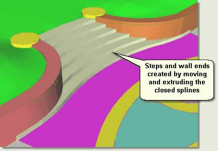
Steps
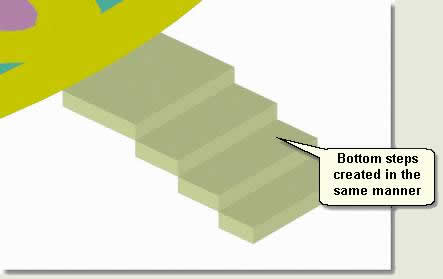
- Select Steps top.06. Using Transform Type-In move to 0.9m above 0
- Select Steps top.05. Move to 0.75m above 0
- Select Steps top.04. Move to 0.6m above 0
- Select Steps top.03. Move to 0.45m above 0
- Select Steps top.02. Move to 0.3m above 0
- Select Steps top.01. Move to 0.15m above 0
- Select all step splines and apply an Extrude modifier to a value of -0.2
- Select Wall ends.01 and Wall ends.02 in turn
- Move the wall end splines to 0.9m above 0 and extrude to 0.15m
- Repeat the process with the bottom steps, this time moving the step splines down in 0.15 intervals, then extruding to -0.2
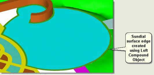
Sundial Surface Edge
- Select Sundial boundary. This will serve as the path for a Loft Compound Object
- Draw a rectangle 0.2m wide and 0.05m long
- Move the pivot point of the rectangle to the bottom left
- Create the sundial surface edge using the sundial surface path as the loft path and the rectangle as the shape, using the Skin Parameters to optimise the loft
NOTE: Further parameters for lofts including how to position shapes accurately on loft paths are explored in ‘Lighting, Materials and Production’
NOTE: This tutorial scene sequence has been saved as kf303_01a/b.max for reference
Donate to CADTutor
If you found this tutorial useful, you might like to consider making a donation. All content on this site is provided free of charge and we hope to keep it that way. However, running a site like CADTutor does cost money and you can help to improve the service and to guarantee its future by donating a small amount. We guess that you probably wouldn't miss $5.00 but it would make all the difference to us.
Local Navigation
Sponsored Links
The Basics
- Dual Dimensions in a Dim…
- UCSICON Options
- "Best of" Basics: Irreg…
- Tool Palette Basics
- Original Dimension Value
- Possible Solutions to th…
- Avoid Using 'Standard' i…
- Shorten the Plot Scales…
- Update the Source File B…
- User Increment Angles fo…
- Drawing Information
- 'Sign Language'
- Rotate with the Copy Opt…
- Use the INSERT Osnap on…
- To or From the Current L…


