3D Tree Exercise
Introduction
 The object behind this exercise is twofold. Firstly it is to give you practice with some of the 3D techniques which you have discovered in the tutorials or to introduce you to them if you haven't seen them before. Secondly it is to demonstrate a reasonably simple method for constructing a convincing 3D tree.
Constructing the Tree
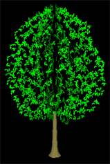
It is quite difficult to construct convincing looking 3D trees in AutoCAD, however, with a few simple 3D commands at your disposal you should be able to create something which is identifiable as a tree and perhaps hint at a species. At the end of this exercise you should have something which looks similar to the illustration on the right. When you have completed the tree you will have a block which can be used in future drawings. Many users keep libraries of such blocks in order to create convincing drawings quickly. Follow the sequence below to complete the exercise.
Setting up the Drawing
- Start a new drawing, click on
 and select "Start from Scratch" from the Create New Drawing dialogue box.
 - Use the Layer command,
 to create three new layers called "CONSTRUCTION", "CANOPY" and "TRUNK". Set the current layer to "CONSTRUCTION" and give the new layers appropriate colours. If you need more information about working with layers, see the "Object Proprties" tutorial.
 - This might be a good time to save your drawing
 . Give it a logical name such as "3D_TREE1". Remember to save your drawing regularly (every 10 to 15 mins) during the drawing session.
 - Using the DDVPOINT command, from the pull-down, create an elevational view of the drawing by setting the vertical angle (the half circle on the right of the dialogue box) to zero. Notice that your UCS icon changes to show the broken pencil to tell you that you cannot draw in this view.
- Use the UCS command to set the current UCS to "View"
 . The UCS icon now reappears as usual except that the "W" is missing, to indicate that you are no longer in the World Co-ordinate System. You are now ready to draw in elevation. For more information on User Co-ordinate Systems, see the "UCS" tutorial.
Creating the Construction Frame
- Draw a rectangle using the RECTANG command, from the pull-down menu or
 from the Draw toolbar.use the height and spread of your tree as dimensions (say 8 high and 6 wide) remember to work in metres. The midpoint of the rectangle base needs to be at the co-ordinate 0,0 so that you can later use this tree as a block insert. Tip: try using -3,0 for the first point and @6,8 when prompted for the second point. This will create a rectangle 8 metres high and 6 metres wide with a base midpoint at 0,0.
 - Now that we have created a rectangular frame for our tree profile we need to draw a line for our Axis of Revolution. Start the LINE command, or
 from the toolbar and draw a line from the midpoint of the rectangle base to the midpoint of the rectangle top. Make sure to use the Midpoint Osnap
  . If you are unsure about using co-ordinate values with AutoCAD, see the "Using Co-ordinates" tutorial for more guidance.
Drawing the Tree Profile

- Draw two polylines, or
 , to describe the profile of your tree, one for the canopy and one for the trunk. Make sure that you join the two polylines end to end, use the Endpoint Osnap,
  . Also make sure that the canopy polyline starts at the midpoint of the rectangle top and that the trunk polyline ends on the rectangle baseline.
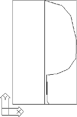
 - You have now drawn all of the constructional elements you need. Your screen should now look something like the illustration on the right. Save your drawing.
Creating the 3D Trunk
- Make the TRUNK layer current and start the REVSURF command,
from the pull-down or
 from the Surfaces toolbar. Select the polyline you drew to represent the trunk profile when prompted for the path curve and then pick the axis. Accept the command defaults and a 3D tree trunk will be generated.
Drawing the Leaves

- Make the CANOPY layer current and use the 3DFACE command, from the pull-down or
 from the toolbar to draw "leaves" on the canopy. Don't draw too many leaves, remember that they will be multiplied later when you use the ARRAY command and this can make the drawing file quite large.
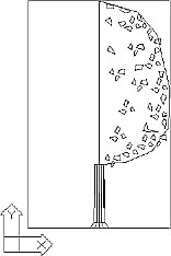
Tip: just draw a few leaf shapes and then use the Multiple option of the COPY command to copy them. When you have finished, your drawing should look something like the illustration on the right.
Creating the Canopy with Array
- Use the UCS command to set the UCS back to "World"
 , you will see the broken pencil icon again.
 - Start the ARRAY command, from the pull-down or
 from the Modify toolbar. Select all of the leaves when prompted and then select the Polar array option. Pick the midpoint of the rectangle base when prompted for the centre point of the array (this may be easier if the TRUNK layer is turned off first), alternatively you could enter the co-ordinate value 0,0 since you know this to be the same point. Enter the number of items, even numbers look best (say 6 or 8). Do not enter a large number, AutoCAD is likely to crash and you may lose your work. Accept the defaults for start angle, 360 degrees and to rotate objects as they are copied. Your canopy will be generated.
Viewing Your 3D Tree
- Turn off the CONSTRUCTION layer, take a look at your tree in 3D (use DDVPOINT) and view the tree from different angles.
- Use the SHADE command to shade the tree. from the pull-down menu. Tip: the leaves will look best if the 256 Color option is used. This is effectively the same as setting the SHADEDGE variable to 0. Experiment with the different Shade options to see what effect they have.
- Save your drawing. Sit back and marvel at your skill.
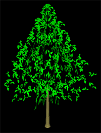
 You may find that the tree doesn't look quite right and that there are gaps in the canopy. If this is the case just go through the process again and use a different leaf pattern or add more leaves. There are lots of ways that you can refine this process to improve the look of the tree. For example you could draw leaves on three different layers and give each layer a slightly different colour to increase the tonal range. By changing the colour of the leaf layers you can hint at seasonal changes. You could draw leaves on both halves of the canopy so that the tree doesn't look too symmetrical when viewed face-on. The key is to experiment. The illustration on the right shows a tree with a conical shape.
Once you are quite happy with your tree and you have saved it you can use it as a block insert in any other drawing. You can do this by using the DDINSERT command, from the pull-down menu when in another drawing. The insert base point of this block will be the base of the tree trunk because you drew the tree with the co-ordinate system origin (0,0) in that location.
If you do decide to keep your tree for future use it is worth tidying the drawing up a little. For example, you don't need to have the construction lines any longer, so erase all of the objects on the "CONSTRUCTION" layer. Once you have done that you can also remove the layer itself using the Layers command or the PURGE command, see the "Object Properties" tutorial for details. This is good drawing practice.
Donate to CADTutor
If you found this tutorial useful, you might like to consider making a donation. All content on this site is provided free of charge and we hope to keep it that way. However, running a site like CADTutor does cost money and you can help to improve the service and to guarantee its future by donating a small amount. We guess that you probably wouldn't miss $5.00 but it would make all the difference to us.
Local Navigation
Sponsored Links
The Basics
- Dual Dimensions in a Dim…
- UCSICON Options
- "Best of" Basics: Irreg…
- Tool Palette Basics
- Original Dimension Value
- Possible Solutions to th…
- Avoid Using 'Standard' i…
- Shorten the Plot Scales…
- Update the Source File B…
- User Increment Angles fo…
- Drawing Information
- 'Sign Language'
- Rotate with the Copy Opt…
- Use the INSERT Osnap on…
- To or From the Current L…


