All Activity
- Past hour
-
Thank you for the reference, I made the Multi getval lisps as had so many lisp's that asked for a value after a value then realise have typed one wrong. Also set default values. The approach being can use in any code, the multi radio buttons being a replace for the Initget function. There are versions like one column or two or even three. Something still on the back burner is write a lisp/dcl code based on dwg objects. Have started.
- Today
-
As a "tangent" (pun intended) I really like the CENTERLINE command. I think it's extremely useful how the associativity is made and stays.
-
.thumb.jpg.615654602253be56b2fbd5d064834780.jpg)
How do you modify a 3D solid without rebuilding it?
indiancad posted a topic in AutoCAD 3D Modelling & Rendering
Sometimes a 3D model is nearly complete, but a design change requires altering one section without affecting the rest of the geometry. Depending on how the solid was created, direct face editing may be quicker than modifying the original profiles and repeating the modeling steps. However, complex intersections and connected faces can make these edits less predictable. When revising an existing 3D solid, do you prefer direct face editing or going back to the original geometry and rebuilding the feature? What makes you choose one over the other? -
Come to think of it, why has Autodesk left that useless "Mark" and "Line" option all of these years? Line is even worse option, way too close to the edge of the circle, arc, et.al., IMO. I prefer mine a good bit past the edges as per my manual drafting days. The Centermark object is technically correct, 3mm/.1200 inch past the edge as default, which matches some information I found on creating them with modern CAD. On thinking this over, that may be a good way to steer this, as mentioned by @Paul Li, they stay with the object. They also allow associative dimensions to work. I do not like the large amount of lines and spaces in the Centermark centerline linetype they use, the Line option of the DIMCENTER mark is correct, the cross, a gap, then continuous line just past the edge, but it is barely past the edge. Mechanical's Line option the center mark you can't even snap to an endpoint on it. I suppose on further reflection I should make some adjustments to the size option, I'll think that over. This was mostly to get rid of and replace the one from the dimdia and dimrad, so it does that, as well as provides the use of associated dimensions.

-
I thought about doing that as well, I may still do it. That looks good. My AutoCAD has been freezing/crashing randomly since they updated my work computer to Windows 11 among other issues, no LISP related issues, just random, often when opening a new drawing or switching drawings occasionally during a command. So I have been going through my old LISPs, etc. and trying to clean them up, add and improve options, test them, etc., as I can and/or as I get to them. Mostly so I can quickly adjust, alter, and improve the drawings as quickly as possible before a crash/freeze. Any suggestions, corrections and/or criticisms, etc. are fine, I will slowly post a few I am happy with as I get them cleaned up. As some may have noticed, I sometimes add a comment in the code where to change some hard coded options, I might or someone else can feel free to add a DCL or options on the commandline. There is always @BIGAL's Multievals, etc. if someone newer to LISP wants to add options, I am sure he will help someone out it getting that done. P.S. Most of my posted on the internet code has a header of some sorts, that's generally for some instructions and usually I place a link to where I posted the code as well as my name, etc. That's mostly for my benefit, I would love to see at least the link to where I posted it (particularly if it was in response to another's request), but feel free to "steal" what you like, with no worries, nor do I need credit. On that issue, the header I posted in my first post, I did add some credit for what I knew I had borrowed, it's in the actual LISP file, too. So please leave those in out of respect. If anyone notices anything else I need to credit, please mention it. P.S.S. You may notice I have a description as a first line, I do that for use in an old LISP from CADALYST site that loads a list of LISPs from a specified folder and shows the name and description, but the description has to be the first line. ;;;CADALYST 11/04 Tip1996: LoadLsp.lsp LISP Manager (c) 2004 Jeffery P. Sanders ;;;--- LoadLsp.lsp - Displays lisp programs with a description. ;;; ;;; ;;;--- For AutoCAD Release 2000+ ;;; ;;; ;;;--- Created on 9/2/04 Revision 0 ;;; ;;; ;;;--- Copyright 2004 by JefferyPSanders.com ;;; All rights reserved. It also has some other LISPs and DCL required.
-
Do you always start a complex 3D part as a solid?
indiancad replied to indiancad's topic in AutoCAD 3D Modelling & Rendering
I also prefer starting with 2D profiles and standard solid tools whenever they can achieve the required shape. Surfaces are useful for complex geometry, but gaps and trimming issues can make solid conversion difficult. I think the best approach depends on the shape and the level of control needed. -
Def going to use some coding from this. Thought id share a few different options that i came up with over the years. check error message agaist a list (if (not (member msg '("Console Break" "Function cancelled" "quit / exit abort"))) (princ (strcat "\nError: " msg)) ) using cond inside setq for default option. (initget "Select Current All") (setq mode (cond ((getkword "\nMode [<Select>/Current/All]: ")) ("Select") ) )
- Yesterday
-
Sure, I know what you mean. I have my own routine i spun years ago that i still use. i use a linetype scale ratio to keep the center with a single set of gaps and centermark. Although it's not perfect, it's good enough for me.
-
I know of that one, but my LISP replaces the centermarks for dimdiameter and dimradius, by selection, by current or all. I could possibly add reactors to mine, not sure it's necessary.
-
Have you tried: https://www.lee-mac.com/associativecenterlines.html ?
-
I tried and tried to get the new Centermark to work nicely out of the box, too hard to get the proper size for starters and just do not care for it for a replacement for the DIMCENTER, the simple Lines work a lot better and allow you to snap associative dimensions so if something changes the center to center and center to end remain correct.
-
When you mention dimension mark I assume you’re referring to AutoCADs original DIMCENTER command which I agree is quite useless. But I do think the number of commands beginning with the word center introduced back in 2017 were a lot more useful since finally the “marks” can now be made associatively to the objects selected.
-
 jstovall13 joined the community
 -
As I state in the header, I found the AutoCAD dimension "MARK" to be less than useful, so over the years I have used my own, eventually writing some LISP, as well as having found the mentioned LISP by alanjt. I really don't care for mucking around with the new CENTERMARK either. Thought I might as well share it, some may find it handy. ;;; Replace Diameter/Radius dimension CenterMarks with two CENTER2 linetype lines. ;;; ;;; https://www.cadtutor.net/forum/topic/99350-center-mark-replacement/#findComment-680408 ;;; ;;; By SLW210 (a.k.a. Steve Wilson) ;;; ;;;| Since AutoCAD in there infinite wisdom makes the default dimdia and dimrad center marks useless by not allowing them to be associated by other dimensions and not allowing an individual color and linetype I came up with this little routine. Much faster, it was using some commands, I went to removing commands. I used to get rid of the default the drew a centermark and copied from center to center, a bit tedious at best. I started with this from Alan J Thompson, so thanks to him. ================================================================ Turn off the centermark for diameter and radius dimensions https://www.cadtutor.net/forum/topic/18792-request-routint-to-turn-off-center-mark-for-single-entity/#findComment-153451 By alanjt|; ;;; ;;; ================================================================ ;;; ================================================================ ;;; CtrMrkRep.lsp ;;; ;;; Replace Diameter/Radius dimension center marks with ;;; two CENTER2 linetype lines. ;;; ;;; ;;; AutoCAD 2018-2026 should work as well as BricsCAD and others. ;;; ;;; ================================================================ ;;; ================================================================ ;;; Original dimensions are retained. ;;; ;;; Replacement geometry: ;;; Layer : CenterMark ;;; Color : ByLayer ;;; Linetype : ByLayer ;;; Layer Color : ACI 5 (Blue) ;;; Layer Linetype : CENTER2 ;;; ;;; Modes: ;;; Select - manually selected DIMDIAMETER/DIMRADIUS ;;; Current - all such dimensions in current Model/Layout space ;;; All - all such dimensions in all paperspace layouts ;;; ;;; Associated dimension center marks: ;;; Disabled using ActiveX acCenterNone. ;;; ;;; Duplicate centers: ;;; Only one centerline cross is created for each unique center ;;; within each Model/Layout space. ;;; ================================================================ CtrMrkRep.lsp
-

Do you always start a complex 3D part as a solid?
ReMark replied to indiancad's topic in AutoCAD 3D Modelling & Rendering
I followed this method as well. I avoid using surfaces whenever possible due to problems (sometimes) with converting them to solids. -
 priyavkum joined the community
 -
 AYYES changed their profile photo
 -
AYYES joined the community
- Last week
-
 KhaDo joined the community
 -

Do you always start a complex 3D part as a solid?
SLW210 replied to indiancad's topic in AutoCAD 3D Modelling & Rendering
I normally start with a 2D shape, extrude, sweep, presspull. revolve, et al. -
Issues with MText in different colours
SLW210 replied to GGuzzler's topic in AutoCAD 2D Drafting, Object Properties & Interface
I would probably call it a Windows 11/AutoCAD 2025 issue, the latest update in mid September was to address the Net 10.0 compatibility among other issues. I just dumped my last 2025 product or I could have tried it on that. My AutoCAD 2026 products are crashing every day since they upgraded me to Windows 11. -

Issues with MText in different colours
GGuzzler replied to GGuzzler's topic in AutoCAD 2D Drafting, Object Properties & Interface
Thanks for all your help everyone, I updated to LT 2027 and no longer appear to have that issue (though I haven't migrated my settings yet so who knows). One of those mysteries, go figure -

Issues with MText in different colours
Steven P replied to GGuzzler's topic in AutoCAD 2D Drafting, Object Properties & Interface
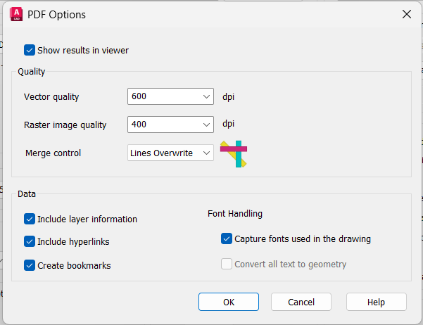
Copy the text into notepad and then copy from there into the drawing usually removes any residual formatting from MS word As SLW210, is the font installed in the PDF viewer? It might be substituting for something close - PDF options should get Capture fonts.... If no luck there try substituting the font for a generic font (Romans or Arial usually work) PDF from my CAD (Full AutoCAD) plots as expected using DWG to PDF.pc3 with these settings:
-

Beyond APPLOAD: A local script manager for those of us with too many LISPs
VicoWang replied to VicoWang's topic in AutoLISP, Visual LISP & DCL
Welcome to share your experience and feedback on the offline mode (Base level) of VedaCAD. For example: 1. Can it replace the appload management plugin? 2. Compared to the appload method, which one is better in terms of management? 3. Is the new machine/local recovery configuration method immediate? 4. Does it cause CAD to lag? 5. How do the advantages and disadvantages compare to the way you used to use (e.g., acaddoc.lsp)? 6. Does it do things outside of your authorization secretly? 7. Can it be used on LT, C3D? 8. What suggestions and feedback do you have? -
Issues with MText in different colours
SLW210 replied to GGuzzler's topic in AutoCAD 2D Drafting, Object Properties & Interface
I doubt if this has anything to do with AutoCAD, usually if the print preview is correct it goes to something past AutoCAD. Autodesk site recommends changing the "Capture fonts used in the drawing" to "Convert all text to geometry" for PDF specific font issues, is this an option for you? Did you try some of the other PDF plotters, full AutoCAD has a few more, I would think LT does as well? Did this start after a Windows update or the AutoCAD update? -

Free Multi Plot Lisp – Fast Batch Printing for AutoCAD, BricsCAD & ZWCAD | Model/Layout, Zone Plotting & PDF Merge
CamDuy replied to CamDuy's topic in AutoLISP, Visual LISP & DCL
V2 update link: https://drive.google.com/drive/folders/16RZS69S2tzZZzFnYW0H6QNQ3klwxB2C6?usp=drive_link If anyone has used it, please share your feedback with me.
-

Issues with MText in different colours
Paul Li replied to GGuzzler's topic in AutoCAD 2D Drafting, Object Properties & Interface
Since you do have the latest updates installed, here are some additional questions: 1) Any difference if the text is in model? 2) Does the same problem occur if you created the text using Lato Regular in LT and not copied it from Word? 3) What happens when you change the pasted text to Arial ttf or to Romans shx? 4) Have you tried installing LT 2026 side by side without migrating settings from LT 2025 to see if the same problem still occurs? -
Do you always start a complex 3D part as a solid?
indiancad posted a topic in AutoCAD 3D Modelling & Rendering
For simple mechanical parts, starting with a 3D solid is usually straightforward. But for parts with complex curved geometry, I sometimes find it cleaner to build the shape as surfaces first and then convert/thicken the result into a solid. The advantage is that the surface geometry can be controlled independently before committing to the final solid form. I’m curious how others approach this: For complex curved parts, do you prefer a solid-first or surface-first workflow—and why? -
Issues with MText in different colours
GGuzzler replied to GGuzzler's topic in AutoCAD 2D Drafting, Object Properties & Interface
-
Issues with MText in different colours
Paul Li replied to GGuzzler's topic in AutoCAD 2D Drafting, Object Properties & Interface
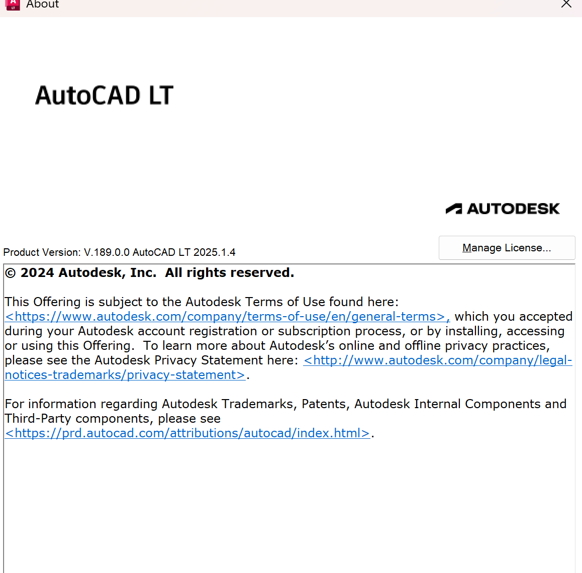
Do you have the latest LT 2025 updates installed? Enter About command, do a screenshot and share this here